Serial Port Protocol
Last Updated on : 2022-02-16 03:31:23download
Overview
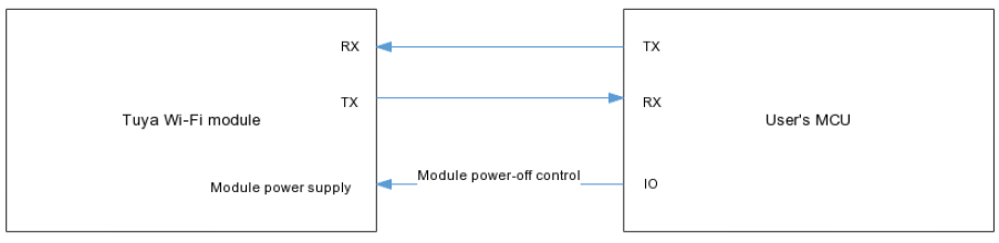
Tuya Wi-Fi general serial port protocol is a customized protocol for Wi-Fi modules of Tuya. It is mainly used for serial port communication between Tuya Wi-Fi modules and other MCU serial ports. The architecture diagram is shown as follows.
Points for attention during development are shown as follows:
-
The whole protocol applies to devices that use Wi-Fi modules and cannot use external power supply. Power-off management is especially important during MCU program development. Under the precondition that functions can be completed, try to reduce the power-on duration of Wi-Fi modules. This is a key point to reduce power consumption. The control flowchart of data uploading is provided. You can select functions in the protocol according to your device features. During development, you can adjust relevant control logics as needed in a real-time way.
-
Many devices can be used normally even when Wi-Fi function is disabled. Due to various reasons, users might not use the Wi-Fi function when they receive the device. In this case, we can design a physical button or relevant options for the device, in order not to power on the Wi-Fi module and cause electrical energy loss. Only when the user enables the button or option, and when the data changes, MCU will power on the Wi-Fi module to transfer relevant data.
Serial communication convention
-
Baud: 9600
-
Data bit: 8
-
Parity check: None
-
Stop bit: 1
-
Data flow control: None
-
MCU: Micro Controller Unit. MCU is connected to Tuya modules through serial ports. Regarding the protocol design, interaction of all packets is designed as full-duplex communication.
Frame format description
| Field | Length (byte) | Description |
|---|---|---|
| Header | 2 | It is fixed as 0x55aa. |
| Version | 1 | It is used for upgrade and extension. |
| Command word | 1 | Specific frame type. |
| Data length | 2 | Big-endian. |
| Data | N | / |
| Checksum | 1 | Start from the header, add up all the bytes, and then divide the sum by 256 to get the remainder. |
Note:
-
All data greater than one byte shall be transmitted with big-endian mode.
-
All examples in the protocol use hexadecimal data.
-
The packets sent by Wi-Fi module time out after 1 second. The resend mechanism will resend three packets.
-
Generally, the same command word adopts synchronous sending and receiving mechanism. One party sends a command, and the other party responds. If the sender fails to receive the correct response packet within the stipulated period, the transmission times out, as shown in the following figure.
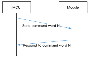
Note: For specific communication mode, see the chapter “Protocol details”.
-
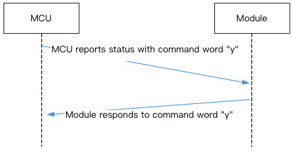
MCU status is reported in a synchronous way. “Command word” of reporting MCU status is y, as shown in the following figure.
MCU statistical data report:
Status data unit
Note:
- Data point command/status data unit is shown as follows:
| Data segment | Length (byte) | Description |
|---|---|---|
| dpid | 1 | Data point serial number. |
| type | 1 | Specific data type of a data point on the IoT console. For more information, see the description of the type field. |
| len | 2 | Number of bytes of the value corresponding to length. For more information, see the description of the type field. |
| value | 1/2/4/N | Expressed with hex, and adopt big-endian transmission when there are more than 1 byte. |
Description of the type field:
| type | Type | Length (byte) | Description |
|---|---|---|---|
| 0x00 | raw | N | Corresponding to raw data point (module pass-through). |
| 0x01 | bool | 1 | Value range: 0x00/0x01. |
| 0x02 | value | 4 | Corresponding to int type, which is expressed with big-endian. |
| 0x03 | string | N | Corresponding to specific string. |
| 0x04 | enum | 1 | Enumeration type, ranging from 0 to 255. |
| 0x05 | bitmap | 1/2/4 | Expressed with big-endian when there are more than 1 byte. |
- For data point command/status data unit, except “raw” type, all other types belong to “obj” type data point.
- “Status data” can contain “command data units” of multiple data points.
Protocol details
Query product information
Note:
-
Product ID: corresponding to product ID (PID) of Tuya IoT console. It is generated by Tuya cloud developer platform to record product information in the cloud.
-
Product information consists of product ID (PID) and MCU software version.
-
Define the format of MCU software version No.: dot-decimal notation, “x.x.x” (0<=x<=99), x is decimal digit.
For example, the module sends the following command:
| Field | Length (byte) | Description |
|---|---|---|
| Header | 2 | 0x55aa |
| Version | 1 | 0x00 |
| Command word | 1 | 0x01 |
| Data length | 2 | 0x0000 |
| Data | 0 | None |
| Checksum | 1 | Start from the header, add up all the bytes, and then divide the sum by 256 to get the remainder |
For example, the module sends the following command:
55 aa 00 01 00 00 00
MCU returns the following command:
| Field | Length (byte) | Description |
|---|---|---|
| Header | 2 | 0x55aa |
| Version | 1 | 0x00 |
| Command word | 1 | 0x01 |
| Data length | 2 | N |
| Data | N | {“p”:“vHXEcqntLpkAl***”, “v”:“1.0.0”} |
| Checksum | 1 | Start from the header, add up all the bytes, and then divide the sum by 256 to get the remainder |
For example, {“p”:“vHXEcqntLpkAl***”,“v”:“1.0.0”}
p represents product ID, vHXEcqntLpkAl***, which is the product ID created by the user on the Tuya IoT console.
v represents MCU version number, which is 1.0.0.
MCU returns example information:
55 aa 00 01 00 24 7b 22 70 22 3a 22 76 48 58 45 63 71 6e 74 4c 70 6b 41 6c 4f 73 79 22 2c 22 76 22 3a 22 31 2e 30 2e 30 22 7d bf
Report the network status of the device
| Network status of device | Description | Status value |
|---|---|---|
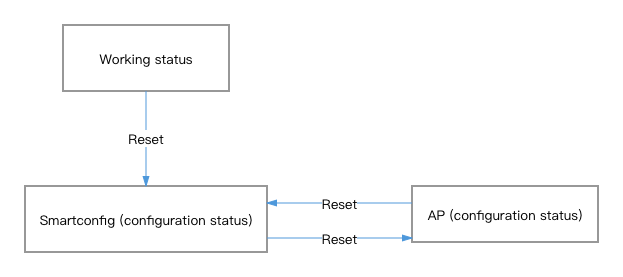
| Status 1 | smartconfig configuration status | 0x00 |
| Status 2 | AP configuration status | 0x01 |
| Status 3 | Wi-Fi has been configured, but not connected to the router | 0x02 |
| Status 4 | Wi-Fi has been configured, and connected to the router | 0x03 |
| Status 5 | Wi-Fi has been connected to the router and the cloud | 0x04 |
Note:
-
When Wi-Fi status of the module changes, Wi-Fi status is sent to MCU.
-
Status packet here is used by MCU device to obtain current status of the module. For status 1 and status 2, MCU shall display the network configuration status.
-
In principle, you shall adopt two network configuration ways. In the first network configuration way, a few routers have compatibility issues. The second network configuration way ensures that the device can be connected to the network.
For example, the module sends the following command:
| Field | Length (byte) | Description |
|---|---|---|
| Header | 2 | 0x55aa |
| Version | 1 | 0x00 |
| Command word | 1 | 0x02 |
| Data length | 2 | 0x0001 |
| Data | 1 | Indicates Wi-Fi working status: 0x00: status 1 0x01: status 2 0x02: status 3 0x03: status 4 0x04: status 5 |
| Checksum | 1 | Start from the header, add up all the bytes, and then divide the sum by 256 to get the remainder |
For example, the module sends the following command:
55 aa 00 02 00 01 04 06 (the device is connected to the router and the cloud)
MCU returns the following command:
| Field | Length (byte) | Description |
|---|---|---|
| Header | 2 | 0x55aa |
| Version | 1 | 0x00 |
| Command word | 1 | 0x02 |
| Data length | 2 | 0x0000 |
| Data | 0 | None |
| Checksum | 1 | Start from the header, add up all the bytes, and then divide the sum by 256 to get the remainder |
MCU returns the following command:
55 aa 00 02 00 00 01
Reset Wi-Fi
Note:
- Status transfer of resetting Wi-Fi is shown as follows:
MCU sends the following command:
| Field | Length (byte) | Description |
|---|---|---|
| Header | 2 | 0x55aa |
| Version | 1 | 0x00 |
| Command word | 1 | 0x03 |
| Data length | 2 | 0x0000 |
| Data | 0 | None |
| Checksum | 1 | Start from the header, add up all the bytes, and then divide the sum by 256 to get the remainder |
MCU sends the following command:
55 aa 00 03 00 00 02
The module returns the following command:
| Field | Length (byte) | Description |
|---|---|---|
| Header | 2 | 0x55aa |
| Version | 1 | 0x00 |
| Command word | 1 | 0x03 |
| Data length | 2 | 0x0000 |
| Data | 0 | None |
| Checksum | 1 | Start from the header, add up all the bytes, and then divide the sum by 256 to get the remainder |
The module returns the following command:
55 aa 00 03 00 00 02
Reset Wi-Fi and select configuration mode
Note:
-
Compared to “Reset Wi-Fi”, with this frame, MCU can select the required configuration mode after the Wi-Fi is reset.
-
You can implement this protocol selectively.
MCU sends the following command:
| Field | Length (byte) | Description |
|---|---|---|
| Header | 2 | 0x55aa |
| Version | 1 | 0x00 |
| Command word | 1 | 0x04 |
| Data length | 2 | 0x0001 |
| Data | 1 | 0x00: enter smartconifg configuration mode 0x01: enter AP configuration mode |
| Checksum | 1 | Start from the header, add up all the bytes, and then divide the sum by 256 to get the remainder |
MCU sends the command to the control module and enters AP configuration mode:
55 aa 00 04 00 01 01 05
The module returns the following command:
| Field | Length (byte) | Description |
|---|---|---|
| Header | 2 | 0x55aa |
| Version | 1 | 0x00 |
| Command word | 1 | 0x04 |
| Data length | 2 | 0x0000 |
| Data | 0 | None |
| Checksum | 1 | Start from the header, add up all the bytes, and then divide the sum by 256 to get the remainder |
The module returns the following command:
55 aa 00 04 00 00 03
Report the real-time status
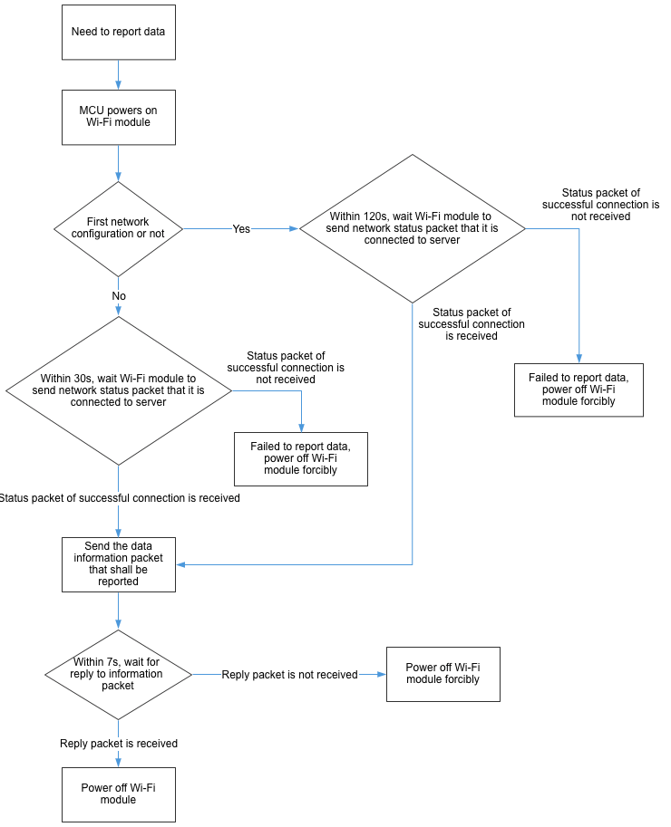
Scenario: If a device has an alert function and requires real-time notification, you can use this command to report the relevant status data.
Note: When MCU needs to report real-time status data, this protocol can be used to report the data.
-
Status data is directly reported to the cloud, so the device shall be connected to the cloud already. Otherwise, the device fails to report the data.
-
This command is a synchronous command. MCU reports the data, and then waits for the result returned by the module. The waiting timeout is 7 seconds.
-
The module sends a network status packet that the server is connected, and then MCU sends the required statistical data packet. The data uploading here does not have storage function. After a period, if the MCU does not receive the network status packet that the server is connected, the MCU will still power off the device. The waiting period is affected by the network and whether it is the first network configuration.
- If it is the first network configuration, it takes much time to transfer from status 3 (Wi-Fi has been configured) to status 5 (cloud connection status), because the device shall be activated and initialized. It takes a longer time if the network is poor, so it is suggested that the waiting period should be 120 seconds.
- If it is not the first network configuration, that is, the network has already been configured, it is suggested that the waiting period should be 30 seconds, considering that a longer waiting period is required in case of poor network.
-
Support the reporting of multiple data units and single data unit. You can select the packet sending mode as needed. For specific data packet, see the following example.
The general flowchart is shown as follows.
MCU sends the following command:
| Field | Length (byte) | Description |
|---|---|---|
| Header | 2 | 0x55aa |
| Version | 1 | 0x00 |
| Command word | 1 | 0x05 |
| Data length | 2 | It depends on the type and number of the status data unit |
| Data | N | One or multiple combined “status data unit” groups |
| Checksum | 1 | Start from the header, add up all the bytes, and then divide the sum by 256 to get the remainder |
The module returns the following command:
| Field | Length (byte) | Description |
|---|---|---|
| Header | 2 | 0x55aa |
| Version | 1 | 0x00 |
| Command word | 1 | 0x05 |
| Data length | 2 | 0x0001 |
| Data | 1 | 0x00: success 0x01: failure |
| Checksum | 1 | Start from the header, add up all the bytes, and then divide the sum by 256 to get the remainder |
Example of reporting “single status data unit”:
The DP of 109 is a Boolean type variable, and the value is 1.
55 aa 00 05 00 05 6d 01 00 01 01 79
Example of reporting “multiple status data units”:
The DP of 109 is a Boolean type variable, and the value is 1.
The DP of 102 is a string type variable, and the value is an ASCII code of “201804121507”.
55 aa 00 05 00 15 6d 01 00 01 01 66 03 00 0c 32 30 31 38 30 34 31 32 31 35 30 37 5d
Report the record type status (with record storage function)
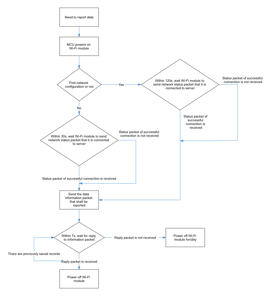
Scenario: A door lock contains multiple data point data, which shall be processed by the server as one record. In case of transient network failure, the data that cannot be reported will be saved through this command. This command can report the status of record type devices.
Note: When MCU requires the whole data that combines multiple data point and that shall be reported as a whole, this command can be used to send the data to Wi-Fi module. If the device is disconnected from network when the data is being reported, the module will save the data. During the next data transmission, the module will upload the data, and report it together with previously saved data.
-
Each time when a previously saved record is reported successfully, the module will send a reply packet in which the command word is 09 and the data is 01. According to the returned packet, MCU will determine it as timeout, and power off. When a record is sent, MCU will wait for 7 seconds. If no reply is received from the module, it is determined that an exception occurs, and the module will be powered off.
-
With a normal network, the module connects the server 4 seconds after the module is powered on. When a record is generated and the device is powered on, wait the Wi-Fi module to send the device network status packet as described in the protocol. The waiting period is affected by the network and whether it is the first network configuration.
- If it is the first network configuration, it takes much time to transfer from status 3 (Wi-Fi has been configured) to status 5 (cloud connection status), because the device shall be activated and initialized. It takes a longer time if the network is poor, so it is suggested that the waiting period should be 120 seconds.
- If it is not the first network configuration, that is, the network has already been configured, it is suggested that the waiting period should be 30 seconds, considering that a longer waiting period is required in case of poor network. If the packet that the module has been connected to the server is not received when the waiting period expires, this command will be reported. After MCU reports the data, MCU will wait for the reporting results returned by the module.
-
Maximum length of data area reported in one record (multiple status data units) is 80. The finally combined and actually saved data length might change, depending on the actual data point. When no network is available, in case of exceeding the stipulated length, Wi-Fi module will return the result that the record cannot be sent.
-
Maximum 20 historical records can be saved by the module. In case of exceeding the limit, the earliest records will be overwritten.
-
The push is successful (00) when the Wi-Fi module receives a packet that a piece of data is successfully pushed, or if network is unavailable, the record is stored in the flash. When there is a successful push and a delay record, it will return 01. In other cases, it will return 02 to represent the push failure.
-
Time data: When the server displays data uploading time, the local uploading time shall prevail. When sending data, MCU also sends local time data, sets the Data[0] time flag bit in the local time protocol to be 1, and transfers data as required by the protocol. When the Wi-Fi module detects that the time flag bit is 1, the time that is transferred by MCU shall prevail (make sure that time data is correct).
The general flowchart is shown as follows.
MCU sends the following command:
| Field | Length (byte) | Description |
|---|---|---|
| Header | 2 | 0x55aa. |
| Version | 1 | 0x00. |
| Command word | 1 | 0x08. |
| Data length | 2 | It depends on the type, number type and number of the status data unit. |
| Data | 7 | Data length is 7 bytes: Data[0] shows whether the data transfer has a local time flag bit. 0 means that the data does not have local time, and the time module thinks that the data is invalid and does not process it. 1 means that the time data is valid. Data[1] is the year, and 0x00 represents the year 2000. Data[2] is the month, ranging from 1 to 12. Data[3] is the date, ranging from 1 to 31. Data[4]is the hour, ranging from 0 to 23. Data[5] is the minute, ranging from 0 to 59. Data[6] is the second, ranging from 0 to 15. |
| N | One or multiple combined “status data unit” groups. | |
| Checksum | 1 | Start from the header, add up all the bytes, and then divide the sum by 256 to get the remainder. |
The module returns the following command:
| Field | Length (byte) | Description |
|---|---|---|
| Header | 2 | 0x55aa. |
| Version | 1 | 0x00. |
| Command word | 1 | 0x08. |
| Data length | 2 | 0x0001. |
| Data | 1 | 0x00: Reported successfully. 0x01: The current record is reported successfully, and previously saved records need to be reported. 0x02: Failed to report. |
| Checksum | 1 | Start from the header, add up all the bytes, and then divide the sum by 256 to get the remainder. |
-
Example of reporting “single status data unit”:
DP 109, Boolean variable, and the value is 1.
55 aa 00 08 00 0c 01 12 04 13 0d 03 1d 6d 01 00 01 01 da//Local time shall prevail.55 aa 00 08 00 0c 00 12 04 13 0d 04 14 6d 01 00 01 01 d1//Server time shall prevail. -
Example of reporting “multiple status data units”:
-
The DP of 109 is a Boolean type variable, and the value is 1.
-
The DP of 102 is a string type variable, and the value is an ASCII code of “201804121507”.
-
55 aa 00 08 00 1c 00 12 04 13 0d 06 04 6d 01 00 01 01 66 03 00 0c 32 30 31 38 30 34 31 32 31 35 30 37 a7 //Server time shall prevail.
55 aa 00 08 00 1c 01 12 04 13 0d 08 2e 6d 01 00 01 01 66 03 00 0c 32 30 31 38 30 34 31 32 31 35 30 37 d4 //Local time shall prevail.
Send module command
Note:
“Send command” is an asynchronous processing protocol. When the MCU receives the control packet, it responds to the module about the reception and controls the device according to the command. The MCU status response is shown in the status reporting of the MCU.
For example, the module sends the following command:
| Field | Length (byte) | Description |
|---|---|---|
| Header | 2 | 0x55aa |
| Version | 1 | 0x00 |
| Command word | 1 | 0x09 |
| Data length | 2 | It depends on the type and number of the “command data unit” |
| Data | N | See the “Status data unit” section |
| Checksum | 1 | Start from the header, add up all the bytes, and then divide the sum by 256 to get the remainder |
The module sends the control command: (The system switch corresponds to DP 3, uses Boolean data type, and the value of 1 indicates power-on)
55 aa 00 09 00 05 03 01 00 01 01 13
Response from the MCU:
| Field | Length (byte) | Description |
|---|---|---|
| Header | 2 | 0x55aa |
| Version | 1 | 0x00 |
| Command word | 1 | 0x09 |
| Data length | 2 | 0x0000 |
| Data | 0 | None |
| Checksum | 1 | Start from the header, add up all the bytes, and then divide the sum by 256 to get the remainder |
ACK response form the MCU:
55 aa 03 09 00 00 0b
Obtain the local time
Note:
-
Start to send a data packet to obtain the local time, after the device is connected to network, that is, the device receives status 5 through the command of “reporting the network status of the device”.
-
After the device is connected to the server, if the network performance is poor, it might fails to obtain time data. Regarding time-dependent devices, such as locks, if local time is not calibrated and it fails to obtain time data, it is required to obtain the time value every 3 seconds, in order to obtain time data successfully.
MCU sends the following command:
| Field | Length (byte) | Description |
|---|---|---|
| Header | 2 | 0x55aa |
| Version | 1 | 0x00 |
| Command word | 1 | 0x06 |
| Data length | 2 | 0x0000 |
| Data | 0 | None |
| Checksum | 1 | Start from the header, add up all the bytes, and then divide the sum by 256 to get the remainder |
MCU obtains local time:
55 aa 00 06 00 00 05
The module returns the following command:
| Field | Length (byte) | Description |
|---|---|---|
| Header | 2 | 0x55aa. |
| Version | 1 | 0x00. |
| Command word | 1 | 0x06. |
| Data length | 2 | 0x0008. |
| Data | Data | Data length is 8 bytes: Data[0] shows whether the time is obtained successfully. 0 represents failure, and 1 represents success. Data[1] is the year, and 0x00 represents the year 2000. Data[2] is month, ranging from 1 to 12. Data[3] is the date, ranging from 1 to 31. Data[4] is the hour, ranging from 0 to 23. Data[5] is the minute, ranging from 0 to 59. Data[6] is the second, ranging from 0 to 59. Data[7] is the week, ranging from 1 to 7, and 1 represents Monday. |
| Checksum | 1 | Start from the header, add up all the bytes, and then divide the sum by 256 to get the remainder. |
The module returns local time data:
55 aa 00 06 00 08 01 12 09 11 10 09 05 01 59
The preceding example represents the local time of Monday, September 17, 2018, 16:09:05.
- If the device is activated and used inside China, local time is Beijing Time (UTC+8).
- If the device is activated and used outside China, local time is the time of the time zone where the device is located.
Wi-Fi functional test
Note:
-
Scan the specific SSID:
tuya_mdev_test, and return the scan result and signal strength percentage. -
Production test command shall be sent after Wi-Fi module is powered on and initialized. That is, the data packet of querying product information is replied. Otherwise, the production test fails or has no result.
-
This command is mostly used for testing the finished product during mass production. There is no restriction on password setting of the production test router. But the bandwidth of the router must be 2.4G.
MCU sends the following command:
| Field | Length (byte) | Description |
|---|---|---|
| Header | 2 | 0x55aa |
| Version | 1 | 0x00 |
| Command word | 1 | 0x07 |
| Data length | 2 | 0x0000 |
| Data | Data | None |
| Checksum | 1 | Start from the header, add up all the bytes, and then divide the sum by 256 to get the remainder |
MCU triggers functional test of the module:
55 aa 00 07 00 00 06
The module returns the following command:
| Field | Length (byte) | Description |
|---|---|---|
| Header | 2 | 0x55aa. |
| Version | 1 | 0x00. |
| Command word | 1 | 0x07. |
| Data length | 2 | 0x0002. |
| Data | 2 | Data length has 2 bytes. Data[0]: 0x00 means failure, and 0x01 means success. When Data[0] is 0x01, which means success, Data[1] is signal strength (0–100, 0: the weakest signal, and 100: the strongest signal). When Data[0] is 0x00, which means failure, if Data[1] is 0x00, the designated SSID is not found. If Data[1] is set to 0x01, the module has not generated an authorization key. |
| Checksum | 1 | Start from the header, add up all the bytes, and then divide the sum by 256 to get the remainder. |
The module returns test results:
55 aa 00 07 00 02 01 50 59
Wi-Fi functional test is successful, and signal strength is 80.
Firmware upgrade
Request to upgrade the Wi-Fi module firmware
Note:
The power-on and power-off of Wi-Fi module are controlled by MCU. To upgrade the Wi-Fi module firmware, MCU can send the following command to obtain the latest firmware.
According to the reply packet of the Wi-Fi module, MCU motherboard determines whether the Wi-Fi module shall be powered off.
- When MCU sends
0acommand, but receives no reply after 5 seconds, MCU powers off the Wi-Fi module. - When the module replies that firmware is being upgraded, MCU must monitor the upgrading time.
- If MCU does not receive a response of successful firmware upgrading within 60 seconds, it is considered that the firmware upgrading fails and the Wi-Fi module needs to be powered off.
MCU sends the following command:
| Field | Length (byte) | Description |
|---|---|---|
| Header | 2 | 0x55aa |
| Version | 1 | 0x00 |
| Command word | 1 | 0x0a |
| Data length | 2 | 0x0000 |
| Data | 0 | None |
| Checksum | 1 | Start from the header, add up all the bytes, and then divide the sum by 256 to get the remainder |
MCU requests to upgrade Wi-Fi firmware
55 aa 00 0a 00 00 09
The module returns the following command:
| Field | Length (byte) | Description |
|---|---|---|
| Header | 2 | 0x55aa |
| Version | 1 | 0x00 |
| Command word | 1 | 0x0a |
| Data length | 2 | 0x0001 |
| Data | 1 | 0x00: (start to detect firmware upgrading) do not power off 0x01: (the latest firmware already) power off 0x02: (upgrading the firmware) do not power off 0x03: (the firmware is upgraded successfully) power off 0x04: (failed to upgrade the firmware) power off |
| Checksum | 1 | Start from the header, add up all the bytes, and then divide the sum by 256 to get the remainder |
Return the module upgrading status:
55 aa 00 0a 00 01 00 0a: it is responded immediately after receiving the upgrading request packet.
55 aa 00 0a 00 01 01 0b: indicates that there is no firmware to upgrade after querying the server.
Request to upgrade the MCU firmware
Note:
-
When MCU receives the response from the module that the firmware is upgraded, it means that MCU upgrade file at the service end has been obtained completely, and data transmission has been completed through serial port. After MCU receives the whole upgrade file, and confirms that the obtained file is correct, the module will send query information again. MCU returns the relevant product information, and fills in the new software version number at the server background.
-
At present, maximum 480K MCU file can be transferred through Over-the-Air Technology (OTA).
-
On the Tuya official website, MCU upgrading method can be configured to app silent upgrade.
MCU sends the following command:
| Field | Length (byte) | Description |
|---|---|---|
| Header | 2 | 0x55aa |
| Version | 1 | 0x00 |
| Command word | 1 | 0x0c |
| Data length | 2 | 0x0000 |
| Data | 0 | None |
| Checksum | 1 | Start from the header, add up all the bytes, and then divide the sum by 256 to get the remainder |
MCU requests MCU firmware upgrading:
55 aa 00 0c 00 00 0b
The module returns the following command:
| Field | Length (byte) | Description |
|---|---|---|
| Header | 2 | 0x55aa |
| Version | 1 | 0x00 |
| Command word | 1 | 0x0c |
| Data length | 2 | 0x0001 |
| Data | 1 | 0x00: (start to detect firmware upgrading) do not power off 0x01: (the latest firmware already) power off 0x02: (upgrading the firmware) do not power off 0x03: (the firmware is upgraded successfully) power off 0x04: (failed to upgrade the firmware) power off |
| Checksum | 1 | Start from the header, add up all the bytes, and then divide the sum by 256 to get the remainder |
Return the module upgrading status:
55 aa 00 0c 00 01 00 0c: it is responded immediately after receiving the upgrading request packet.
55 aa 00 0c 00 01 01 0d : indicates that there is no firmware to upgrade after querying the server.
Notification of MCU upgrade packet size
Note:
When MCU receives an upgrade startup packet, the upgrade file size can be known. The module starts to obtain MCU upgrade packet from the service end, and then send the relevant data packet that is transmitted by the upgrade packet.
For example, the module sends the following command:
| Field | Length (byte) | Description |
|---|---|---|
| Header | 2 | 0x55aa |
| Version | 1 | 0x00 |
| Command word | 1 | 0x0d |
| Data length | 2 | 0x0004 |
| Data | 4 | The number of bytes of firmware packet, the data type is an unsigned integer, and the data storage is in big-endian mode |
| Checksum | 1 | Start from the header, add up all the bytes, and then divide the sum by 256 to get the remainder |
The module sends file packet size:
55 aa 00 0d 00 04 00 00 68 00 78: the size of firmware packet is 26624 bytes, namely 26 KB.
MCU returns the following command:
| Field | Length (byte) | Description |
|---|---|---|
| Header | 2 | 0x55aa |
| Version | 1 | 0x00 |
| Command word | 1 | 0x0d |
| Data length | 2 | 0x0000 |
| Data | 0 | None |
| Checksum | 1 | Start from the header, add up all the bytes, and then divide the sum by 256 to get the remainder |
ACK response from the MCU:
55 aa 00 0d 00 00 0c
Upgrade packet transmission
Note:
-
The data format of upgrade packet transmission: packet offset (unsigned short) + packet data.
-
If MCU receives the frame with data length equal to 4 and the upgrade packet offset is equal to or greater than the size of firmware, the packet transmission ends.
For example, the module sends the following command:
| Field | Length (byte) | Description |
|---|---|---|
| Header | 2 | 0x55aa. |
| Version | 1 | 0x00. |
| Command word | 1 | 0x0e. |
| Data length | 2 | The data length is the sum of 0x0004 and the data packet length. |
| Data | N | The first 4 bytes are fixed as packet offset, and the latter bytes are the packet content. |
| Checksum | 1 | Start from the header, add up all the bytes, and then divide the sum by 256 to get the remainder. |
The module sends file data:
If the file to be upgraded has 530 bytes, under this circumstance, the MCU can skip the response for the last data packet.
-
For the first packet data, packet offset is 0x00000000, and data packet length is 256.
55aa 00 0e 0104 00000000 xx…xx XX -
For the second packet data, packet offset is 0x00000100, and data packet length is 256.
55aa 00 0e 0104 00000100 xx…xx XX -
For the third packet data, packet offset is 0x00000200, and data packet length is 18.
55aa 00 0e 0016 00000200 xx…xx XX -
For the last packet data, packet offset is 0x00000212, and data packet length is 0.
55aa 00 0e 0004 00000212 xx...xx XX
MCU returns the following command:
| Field | Length (byte) | Description |
|---|---|---|
| Header | 2 | 0x55aa |
| Version | 1 | 0x00 |
| Command word | 1 | 0x0e |
| Data length | 2 | 0x0000 |
| Data | 0 | None |
| Checksum | 1 | Start from the header, add up all the bytes, and then divide the sum by 256 to get the remainder |
Confirm each data packet of MCU:
55 aa 00 0e 00 00 0d
Query the signal strength of the currently connected router
Note:
With this command, query the signal strength of the router that is connected to the device currently. The precondition is that device network status packet is received, and the device is connected to the router successfully. Otherwise, the failure result will be returned.
MCU sends the following command:
| Field | Length (byte) | Description |
|---|---|---|
| Header | 2 | 0x55aa |
| Version | 1 | 0x00 |
| Command word | 1 | 0x0b |
| Data length | 2 | 0x0000 |
| Data | 0 | None |
| Checksum | 1 | Start from the header, add up all the bytes, and then divide the sum by 256 to get the remainder |
MCU obtains the strength of the connected router:
55 aa 00 0b 00 00 0a
The module returns the following command:
| Field | Length (byte) | Description |
|---|---|---|
| Header | 2 | 0x55aa. |
| Version | 1 | 0x00. |
| Command word | 1 | 0x0b. |
| Data length | 2 | 0x0002. |
| Data | 2 | Data length has 2 bytes. Data[0]: 0x00 means failure, and 0x01 means success. When Data[0] is set to 0x01, which means success, Data[1] is signal strength (0–100, 0: the weakest signal, and 100: the strongest signal). When Data[0] is 0x00, which means failure, if Data[1] is 0x00, the device fails to connect the router. |
| Checksum | 1 | Start from the header, add up all the bytes, and then divide the sum by 256 to get the remainder. |
Module returns current value of strength (80):
55 aa 00 0b 00 02 01 50 5D
Obtain DP cache command
Note:
For the sensors with setting or control features, DP sending function shall be added. If a panel sends a command when the device is offline, the command is cached in the cloud. The device will obtain it later. The cache command is incremental mode. The obtained commands will not be sent again next time.
MCU sends the following command:
| Field | Length (byte) | Description |
|---|---|---|
| Header | 2 | 0x55aa |
| Version | 1 | 0x00 |
| Command word | 1 | 0x10 |
| Data length | 2 | N |
| Data | dp_num(1byte) + dp_1(byte) +…+ dp_n(1byte) | If dp_num is 0, it will query all the DPs |
| Checksum | 1 | Start from the header, add up all the bytes, and then divide the sum by 256 to get the remainder |
The lock obtains the cache command of dp115, dp114, and dp113:
55 AA 00 10 00 04 03 73 72 71 6C
The module returns the following command:
| Field | Length (byte) | Description |
|---|---|---|
| Header | 2 | 0x55aa. |
| Version | 1 | 0x00. |
| Command word | 1 | 0x10. |
| Data length | 2 | It depends on the type and number of the “status data unit”. |
| Data | result(1byte) + dp_num(1byte) + dp_1(byte) +…+ dp_n(1byte) | “Status data unit” group, return DP data with cache command. Result: it indicates whether the command is obtained successfully. Result 0 means failure. DP data will not be indicated, and data content length is 1. Result 1 means success. dp_num: If dp_num is 0, it is considered that there is no cache command currently. |
| Checksum | 1 | Start from the header, add up all the bytes, and then divide the sum by 256 to get the remainder. |
The module returns the following data, which means to lock the door after 30 seconds.
55 AA 00 10 00 14 01 03 73 01 00 01 01 72 04 00 01 01 71 02 00 04 00 00 00 1E AA
- DP115 is automatic lock, Boolean type, meaning to close the door automatically or not.
- DP 114 is delayed lock selection, enumeration type, meaning to lock the door at once or continue timing.
- DP 113 is numeric type, and the unit is second.
Version history
| Version | Creation/revision description | Date | Remark |
|---|---|---|---|
| 1.0.5 | Modify | 20200417 | Modified the waiting period for network status packet of real-time status reporting and record type data reporting |
| 1.0.4 | Modify | 20190527 | Added the command to obtain DP cache |
| 1.0.3 | Modify | 20180719 | Added the commands to trigger MCU upgrade and file transfer |
| 1.0.2 | Modify | 20180419 | 1. Added command sending 2. Added the reporting channel of the whole record type data (store the previous records) 3. Added the command for MCU to trigger firmware upgrade of the Wi-Fi module 4. Added the command to query the signal strength of currently connected router 5. Added reference flowcharts and improve descriptions |
| 1.0.1 | Modify | 20180205 | 1. Modified the terms 2. Added some notes |
| 1.0.0 | The first release | 20170905 | The first release |
Is this page helpful?
YesFeedbackIs this page helpful?
YesFeedback


