MCU SDK Porting
Last Updated on : 2022-03-29 03:55:13download
The MCU SDK contains all you need to get started with MCU development, such as functions and sample code. The SDK is automatically generated based on the product features defined on the Tuya IoT Platform. This topic describes how to port the MCU SDK to your project.
Overview
The MCU SDK is automatically generated based on the product features defined on the Tuya IoT Platform. To facilitate your integration with Tuya’s Cat.1 IoT general serial protocol, the MCU SDK has built-in support for communication and protocol parsing. You can add this SDK to existing projects and complete the required configuration to implement the MCU program development.
Resource requirements
SDK requirements for the MCU are as follows. If your MCU does not have sufficient resources, you can refer to the functions in the SDK for integration with Tuya’s protocol.
- Memory: 4 KB
- RAM: About 100 bytes of the RAM are required, depending on the data length of the data point (DP). If you enable OTA updates, it must be greater than 260 bytes.
- Nested function: 9-level.
File structure
| File | Description |
|---|---|
mcu_api.c |
Contains functions that can be called. |
mcu_api.h |
Contains declarations for functions in mcu_api.c. |
protocol.c |
Contains functions for processing protocol data. You can add code to related functions as needed and get data sent by the Cat.1 module to the MCU. |
protocol.h |
Contains parameters that the MCU sends to the Cat.1 module for initialization, macros defined for custom functions, and declarations for functions in the protocol.c. |
system.c |
Contains the implementation of parsing the serial protocol. |
system.h |
Contains definitions of commands and some global variables, and declarations for functions in the system.c. |
cellular.h |
Contains macro definitions for Cat.1 communication. |
How to port SDK
- Program the MCU and port the SDK.
- Check macro definitions in
protocol.h. - Port
protocol.cand call functions. - Add the function call for DP data communication.
- Add the function of device pairing and LED indicator.
- Add the production test feature.
Programming and porting
-
In your original project, initialize the MCU peripherals, including serial port, external interrupt (button), timer (indicator flickering), and more.
-
Copy the
.cand.hfiles in the MCU SDK folder to your project directory where your other.cand.hfiles are located.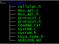
Check macro definitions in protocol.h
Product information
-
Define product ID (PID):
PRODUCT_KEYis the macro defined for the PID. PID is the unique identifier of each product and can be found on the Smart Products page on the Tuya IoT Platform.If the
PRODUCT_KEYand the PID are inconsistent, you can go to Hardware Development > Download Documents section, and download the latest SDK.#define PRODUCT_KEY "ax23eawjo4np****" -
Define MCU version number:
MCU_VERdefines the software version, which defaults to1.0.0. If you enable OTA updates for the MCU firmware, you need to add the new MCU version number after updates.#define MCU_VER "1.0.0" -
Define power consumption type:
MODULE_POWERdefines power consumption mode, which defaults to0. If you define the value to1, the Cat.1 module can run in low power mode. -
Define the type of cellular module:
CELLULAR_MODULE_TYPEdefines module type, which defaults to0indicating LZ201 is used. If you use the LZ211 module and GNSS feature, define the type to1.
Set OTA updates (optional)
-
Enable OTA updates. To support OTA firmware updates, define
SUPPORT_MCU_FIRM_UPDATE. OTA updates are disabled by default.//#define SUPPORT_MCU_FIRM_UPDATE // Enable OTA firmware updates, which are disabled by default. -
Define the update package size in a single packet.
#ifdef SUPPORT_MCU_FIRM_UPDATE
#define PACKAGE_SIZE                   0        // One update package is 256 bytes.
//#define PACKAGE_SIZE                   1        // One update package is 512 bytes.
//#define PACKAGE_SIZE                   2        // One update package is 1024 bytes.
#endif
For more information about the OTA updates, see Update Firmware.
Things to note
- OTA updates read and write flash memory. The system needs to read data and verify whether the correct data is written to flash memory.
- Specify a timeout period for OTA updates so that the MCU will not always be in the data reception status in case of OTA failure.
- Each OTA packet has offset information, which can be used to detect duplicate packets or packet loss.
Transmission and reception buffer (optional)
-
Serial receive buffer: The buffer size depends on how often serial data processing is called. If the MCU can quickly process serial data, the buffer size can be reduced.
-
Serial transmit buffer: The buffer size must be greater than the maximum length of DP data.
-
Buffer for serial data processing: The buffer size must be greater than the maximum length of DP data. If OTA updates and specific weather services are enabled, the buffer size must be greater than the maximum amount of data.
/******************************************************************************
     3: Define transmission and reception buffer: If your MCU has insufficient RAM, you can change the buffer size to 24 bytes.
******************************************************************************/
#ifndef SUPPORT_MCU_FIRM_UPDATE
#define CELLULAR_UART_RECV_BUF_LMT          16  // The serial receive buffer size, which can be reduced if your MCU has insufficient RAM.
#define CELLULAR_DATA_PROCESS_LMT           24  // The buffer size for serial data processing. It depends on the amount of DP data but must be greater than 24 bytes.
#ifdef SUPPORT_WIFI_LOCATION
#define CELLULAR_DATA_PROCESS_LMT          700
#endif
#else
#define CELLULAR_UART_RECV_BUF_LMT          128  // The serial receive buffer size, which can be reduced if your MCU has insufficient RAM.
// Set the proper buffer size. Consider the defined update package and specific weather services, if applicable.
#define CELLULAR_DATA_PROCESS_LMT           300  // The buffer size for serial data processing. When OTA updates are enabled, if you set the size of a single update package to 256 bytes, the buffer size must be greater than 260 bytes. If weather services are also enabled, more buffer is required.
//#define CELLULAR_DATA_PROCESS_LMT           600  // The buffer size for serial data processing. When OTA updates are enabled, if you set the size of a single update package to 512 bytes, the buffer size must be greater than 520 bytes. If weather services are also enabled, more buffer is required.
//#define CELLULAR_DATA_PROCESS_LMT           1200  // The buffer size for serial data processing. When OTA updates are enabled, if you set the size of a single update package to 1024 bytes, the buffer size must be greater than 1030 bytes. If weather services are also enabled, more buffer is required.
#endif

#define CELLULAR_UART_SEND_BUF_LMT         48  // It depends on the amount of DP data but must be greater than 48 bytes.
#ifdef SUPPORT_WIFI_LOCATION
#define CELLULAR_UART_SEND_BUF_LMT         256
#endif
/******************************************************************************
The working mode of Cat.1 module (required)
-
If the reset button and LED indicator for network status are connected to the MCU, the module works with the MCU to process network events, which is most commonly used. You need to comment out the macro
CELLULAR_CONTROL_SELF_MODE.//#define CELLULAR_CONTROL_SELF_MODE // The module processes the reset button and LED indicator itself. If you use an external reset button or LED indicator, disable this macro. -
If the reset button and LED indicator for network status are connected to the Cat.1 module, the module processes network events itself. You need to enable the macro
CELLULAR_CONTROL_SELF_MODE. Specify the GPIO pin connected to the reset button inCELLULAR_RESERT_KEYas per your circuit diagram.If the module works in the self-processing mode, the LED indicator must be connected to the pin for
NET_MODE.#define CELLULAR_STATE_KEY 0 // The LED indicator for network status is fixed to be NET_MODE, so you can define this macro any way you want. #define CELLULAR_RESERT_KEY 21 // The reset button of the module. Specify the actual GPIO pin in this macro.
Enable production test feature (optional)
The production test feature for Cat.1 module is enabled by default. To help you smoothly and efficiently carry out mass production, it is recommended to enable the production test feature.
#define CELLULAR_TEST_ENABLE // Enable the production test feature. The test items include SIM cards and radio frequency (RF).
Weather services (optional)
After the module is connected to the router, you can define WEATHER_ENABLE to enable weather services. Once the module is connected to the cloud, the server sends weather data immediately and then every 30 minutes.
-
Enable weather services. Define
WEATHER_ENABLE.//#define WEATHER_ENABLE // Enable the weather service. -
Specify the supported weather service. You can select the supported weather parameters from the
weather_choosearray in theprotocol.cfile.#ifdef WEATHER_ENABLE /** * @var weather_choose * @brief The array of weather parameters. * @note You can define the supported parameters and comment out the undesired ones. */ const i8 *weather_choose[WEATHER_CHOOSE_CNT] = { "temp", "humidity", "condition", "pm25", /*"pressure", "realFeel", "uvi", "tips", "windDir", "windLevel", "windSpeed", "sunRise", "sunSet", "aqi", "so2 ", "rank", "pm10", "o3", "no2", "co", "conditionNum",*/ }; #endif -
Specify the number of supported weather conditions. Define the number of supported weather conditions in
WEATHER_CHOOSE_CNT.#define WEATHER_CHOOSE_CNT 4 // The number of supported weather conditions. -
Specify the number of days for which the server returns forecast data. The module with the new version of the firmware supports a 7-day weather forecast. You can define the number of days for which the server returns forecast data in the macro
WEATHER_FORECAST_DAYS_NUM.1: returns the weather of the current day.0or greater than7: returns an error. Weather services failed to be enabled.
#define WEATHER_FORECAST_DAYS_NUM 1 // Specify the number of days for which the API returns forecast data.The weather data sent by the module contains information about the forecast days.
0indicates the current day.
Port protocol.c file and call functions
-
Copy the
cellular.hfile to the folder where cellular files are stored, such as themain.cfolder. -
Call
cellular_protocol_init()in themcu_api.cfile after the MCU serial port and other peripherals are initialized. -
Specify the function of single-byte data transmission in
uart_transmit_outputin theprotocol.cfile, and delete#error./** * @brief Send serial data * @param[in] {value} The one byte of data to be sent by the serial port. * @return Null */ void uart_transmit_output(u8 value) { #error "Specify the function of transmitting data from the MCU serial port and delete this line" /* //Example: extern void Uart_PutChar(u8 value); Uart_PutChar(value); // Serial port transmitting function */ } -
In the interrupt handler function for serial data reception, call
uart_receive_inputin themcu_api.cfile. Use the returned value as the parameter.void USART3_IRQHandler(void) { unsigned char Res=0; if((USART3->SR&UART_FLAG_RXNE) != 0) { Res=USART3->DR; uart_receive_input(Res); } } -
After the MCU executes the
while(1)loop, it calls thecellular_uart_service()function in themcu_api.cfile. The sample code inmain.cis as follows:#include "celluluar.h" ... void main(void) { cellular_protocol_init(); ... while(1) { cellular_uart_service(); ... } ... }The MCU must directly call
cellular_uart_service()in themcu_api.cduringwhile(1)loop. After the program is initialized, if an interrupt service routine (ISR) is necessary, you must keep it as short as possible and not call the data reporting function to avoid loss of data.
Call DP data communication function
For more information, see MCU SDK Porting.
Add the function of device activation and LED indicator.
The function of pairing and LED indicator is required only when the module works with the MCU to process network events.
To implement device activation, add the pairing command and LED indicator function. If the module works with the MCU to process network events, you can customize the ways to activate devices and indicate pairing status. Generally, you can set the keypress trigger and fast or slow LED flickering.
Device activation command
mcu_reset_cellular() can implement device activation, which is triggered by keypress and called in key processing function.
Then, the Cat.1 module is reset and the activation information is cleared. When the module connects to a cellular network, it is pending activation.
Pairing guide
To get Cat.1 module’s network status, call mcu_get_cellular_connect_status() during while(1) loop. Write the flickering mode of the LED indicator according to the network status.
| Network status | Description | Status value | LED indicator |
|---|---|---|---|
| Status 1 | The SIM card is not inserted. | 0 | The LED indicator is steady on. |
| Status 2 | Search for cellular networks. | 1 | The LED indicator flickers at an interval of 300 milliseconds. |
| Status 3 | The device is registered with the cellular network. | 2 | The LED indicator flickers at an interval of 1,000 milliseconds. |
| Status 4 | The device gets an IP address. | 3 | The LED indicator flickers at an interval of 2,000 milliseconds. |
| Status 5 | The device is connected to the cloud. | 4 | The LED indicator flickers at an interval of 3,000 milliseconds. |
| Status 6 | SIM card registration is denied. | 5 | The LED indicator flickers at an interval of 100 milliseconds. |
Call mcu_get_cellular_connect_status() function to get connection status.
void main(void)
{
	...
	while(1)
	{
	    ...
	    switch(mcu_get_cellular_connect_status())
	    {
	        case NO_SIM:
	            // No SIM card is detected. LED is steady on.
	        break;
	        case SEARCH_NETWORK:
	            // Search for cellular network. LED flickers at an interval of 300 milliseconds.
	        break;
			case LOGINED_DISCONNECTED:
				// The device is registered with the cellular network. LED flickers at an interval of 1,000 milliseconds.
	        case CONNECTED_GET_IP:
	            // The device gets an IP address. LED flickers at an interval of 2,000 milliseconds.
	        break;
	        case CONNECTED_CLOUD:
	            // The device is connected to the cloud. LED flickers at an interval of 3,000 milliseconds.
	        break;
	        default:break;
	    }
	    ...
	}
}
Add production test feature (optional)
The production test supports the following four test items:
- SIM card detection: A SIM card must be inserted.
- RF calibration: Test whether the RF of the Cat.1 module is calibrated.
- Module authorization: Test whether the Cat.1 module is authorized. An unauthorized module cannot connect to the cloud.
- Signal strength: It ranges from 0 to 31. 4G antenna must be connected.
Enable production test. Define SET_FEATURE_TEST_ENABLE, which is disabled by default.
//#define SET_FEATURE_TEST_ENABLE // Enable module self-test.
The MCU calls mcu_set_feature_test() function in mcu_api.c to enable module self-test.
/**
 * @brief  Module self-test starts.
 * @param  Null
 * @return Null
 * @note   The MCU calls this function.
 */
void mcu_set_feature_test(void)
{
	cellular_uart_write_frame(GET_FEATURE_TEST_CMD, MCU_TX_VER, 0);
}
The MCU adds processing functions based on the response to the self-test from the module. protocol.c has an implementation of get_feature_test_result().
#ifdef SET_FEATURE_TEST_ENABLE
/**
 * @brief  Get the result of the module self-test.
 * @param[in] {sim_st}  SIM card status. 1 indicates SIM card is detected. 0 indicates SIM card is not detected.
 * @param[in] {auth}  Authorization test result. 1 indicates the module is authorized. 0 indicates the module is not authorized.
 * @param[in] {rf}  RF calibration test result. 1 indicates RF is calibrated. 0 indicates RF is not calibrated.
 * @param[in] {signal}  Get signal strength, ranging from 0 to 31.
 * @return Null
 * @note   To be implemented by the developer.
 */
void get_feature_test_result(u8 sim_st,u8 auth,u8 rf,u8 signal)
{
	#error "Complete the RSSI fetch processing code yourself and delete the line"
}
#endif
Communication between MCU and Cat.1 module
Data communication must start after the initialization is completed.
Frame format
For more information about frame format, see Serial Port Protocol.
Initialization communication
After the MCU and the module are powered on, the initialization configuration starts. Initialization communication includes but is not limited to:
- Verify whether the MCU and the module work properly.
- Verify whether the connection works properly.
- Get the data required for module activation.
- Get the working mode of the module.
Heartbeat
A heartbeat is a type of communication packet between the module and the MCU to check whether the communication was lost. We recommend that the frame of the first communication between the MCU and the module is used as the heartbeat. The communication can work properly only when the heartbeat is sent and responded successfully.
Query product information
After the module builds communication with the MCU, it will query the MCU firmware version and the following information.
- PID: product ID, used to activate the product.
- Version number: MCU firmware version number, used to verify whether the OTA updates are successful.
- Pairing mode: the pairing mode of the module.
Set working mode of the module
The module works with the MCU to process the network event or processes it itself. The working mode is determined by the hardware connection of the LED indicator and reset button on the Cat.1 module.
The following figure shows the initialization communication.

Relation between DP data reporting and network status
Through the cloud, the device can report DP data to the app and the app can send commands to the device.
If the Cat.1 module runs in status 4, it indicates the device is connected to the router and the cloud. DP data reporting can work properly.
OTA transmission or file download
This section describes the OTA data communication between the MCU and the Cat.1 module.
File download works the same way as OTA data communication.
-
OTA starts
- If the Cat.1 module does not receive a response from the MCU within five seconds, it will resend the packet three times. If the MCU still does not respond, the OTA updates fail.
- If the total update package size exceeds the processing capacity of the MCU, the MCU does not respond, and the module will exit OTA updates. In this case, you should check whether the updates uploaded on the Tuya IoT Platform are correct.
-
OTA data transmission starts
After sending an OTA packet, if the Cat.1 module does not receive a response from the MCU within five seconds, it will resend the packet three times. If the MCU still does not respond, the OTA updates fail.
- If the MCU detects incorrect OTA data, it does not respond. In this case, check the data offset of the OTA packet to avoid duplicate packets or packet loss.
- If the MCU processes OTA data too slowly, the module will frequently resend data. Check the data offset of the OTA packet to avoid duplicate packets or packet loss. In this case, you can reduce the update package size.
-
OTA transmission is completed
You can determine whether the OTA transmission is completed in the following two ways.-
The frame length is
0x0004, indicating the OTA packet is zero bytes. -
The data offset is equal to the total update package size contained in the frame that the Cat.1 module sends to the MCU for initiating OTA updates.
We recommend using both ways to verify OTA transmission.
-
Cellular-specific communication
The macro definition CELLULAR_SERVICE_ENABLE in the protocol.c specifies cellular service interfaces.
#define CELLULAR_SERVICE_ENABLE // Enable cellular services.
Cellular modes
The Cat.1 module can work in the following two cellular modes. The fully-operational mode is the default.
- Fully-operational mode
- Airplane mode
Get the cellular mode.
The MCU calls mecu_get_cellular_work_mode() in mcu_api.c to send message to the Cat.1 module to get the current cellular mode.
/**
 * @brief  Get the cellular mode.
 * @param  Null
 * @return Null
 * @note  To be implemented by the developer.
 */
void mcu_get_cellular_work_mode(void)
{
	u16 length = 0;
	length = set_cellular_uart_byte(length, GET_CELLULAR_WORK_MODE);
	cellular_uart_write_frame(GET_CELLULAR_CMD, MCU_TX_VER, length);
}
The MCU gets the current cellular mode through get_cellular_work_mode_result() in protocol.c. Delete the #error line after you complete the code to get the cellular mode.
/**
 * @brief  Get the cellular mode.
 * @param[in] {result} work mode
 * @return Null
 * @note   To be implemented by the developer.
 */
void get_cellular_work_mode_result(u8 result)
{
	#error "Complete the work mode fetch processing code yourself and delete the line"

	switch(result) {
	    case 1:
 	        // Fully-operational mode
	    break;

	    case 4:
	        // Airplane mode
	    break;

	    default:break;
	}
}
Set the cellular mode
The MCU calls mcu_set_cellular_mode() in mcu_api.c to send message to the Cat.1 module to get the current cellular mode.
/**
 * @brief  The MCU sets the cellular mode.
 * @param[in] {mode} Specified cellular mode.
 * @ref        1: Fully-operational mode
 * @ref        4: Airplane mode
 * @return Null
 * @note   1: The MCU calls these functions.
 *         2: If set_cellularmode_flag is true, the cellular mode is successfully set.
 *         3: If the module processes network events itself, the MCU does not need to call this function.
 */
void mcu_set_cellular_mode(u8 mode)
{
	u8 length = 0;

	set_cellularmode_flag = SET_CELLULARCONFIG_ERROR;

	length = set_cellular_uart_byte(length, mode);

	cellular_uart_write_frame(SET_CELLULAR_WORK_MODE, MCU_TX_VER, length);
}
The MCU calls mcu_get_cellular_mode_flag() in mcu_api.c to determine whether the cellular mode is successfully set.
Positioning function (optional)
Three types of positioning functions are provided.
-
Global Navigation Satellite System (GNSS) positioning
The LZ201-CN module must work with the external GUC300 GNSS positioning module. The GUC300 module must be connected to the UART2 on the LZ201-CN module. The LZ211-CN module has a built-in GNSS receiver. After the GNSS is enabled, the power consumption will increase, and the current will increase by 30 mA on average.
-
Wi-Fi positioning
Wi-Fi positioning is typically used for indoor scenarios.
-
Location-based service (LBS) positioning
A base station positioning method.
To support the positioning function, define GNSS_SERIVCE_ENABLE, which is disabled by default.
//#define GNSS_SERIVCE_ENABLE // Enable the positioning service. This service is disabled by default.
GNSS positioning
Enable or disable GNSS positioning
GNSS positioning is disabled by default. The MCU calls the mcu_control_gnss() in mcu_api.c to enable or disable GNSS positioning.
If you use the LZ211 module that has a built-in GPS, you should supply power for the GPS with the interface mcu_control_gnss_power on using the GNSS service. When the power status is in firmware loading completed, you can call mcu_control_gnss() to enable GPS positioning.
Sample code:
/**
 * @brief  Enable or disable GNSS positioning
 * @param  [in] {enable} True: enabled. False: disabled
 * @param  [in] {mode} Specifies the mode of GNSS positioning.
 * @return Null
 * @note   To be implemented by the developer.
 */
void mcu_control_gnss(bool_t enable,GNSS_ATTACH_MODE_e mode)
{
	u16 length = 0;
	u8 cmd[3] = {0};
	cmd[0] = SET_CELLULAR_CTRL_GNSS;
	cmd[1] = enable;
	cmd[2] = mode;
	length = set_cellular_uart_buffer(length, cmd,sizeof(cmd));
	cellular_uart_write_frame(SET_CELLULAR_CMD, MCU_TX_VER, length);
}
The enable and mode are the two important parameters. The mode defines which navigation satellite system the GNSS module uses.
The specific navigation satellite systems are defined in the system.h.
// The modes of GNSS positioning
typedef enum{
	GNSS_ATTACH_MODE_GPS_BD,         // Global Positioning System (GPS) plus BeiDou Navigation Satellite System (BDS)
	GNSS_ATTACH_MODE_GPS_GL,      // GPS plus Global Navigation Satellite System (GLONASS)
	GNSS_ATTACH_MODE_GPS,            // GPS
	GNSS_ATTACH_MODE_BD,          // BDS
	GNSS_ATTACH_MODE_GL,            // GLONASS
	GNSS_ATTACH_MODE_GPS_GA,      // GPS plus Galileo satellite navigation
}GNSS_ATTACH_MODE_e;
GNSS_ATTACH_MODE_GPS_BD is the default system. Currently, GUC300 and LZ211 modules do not support GNSS_ATTACH_MODE_GL and GNSS_ATTACH_MODE_GPS_GA.
get_set_gnss_result() of protocol.c implements the result of enabling or disabling GNSS positioning. This function is completed by yourself.
/**
 * @brief  Get the result of enabling GNSS.
 * @param[in] {gnss_status}  Set the return value of GNSS status.
 * @param[in] {gnss_mode}  The returned GNSS mode.
 * @return Null
 * @note   To be implemented by the developer.
 */
void get_set_gnss_result(u8 gnss_status, u8 gnss_mode)
{
	#error "Complete the code for GNSS result and then delete this row."
	if (!gnss_status) {
	    // Failed to set.
	}
       else {
             if (!gnss_mode) {
                 // Failed to set.
             }
            else {
                // Set successfully.
            }
        }
}
Reset GNSS module
The MCU calls mcu_reset_gnss() in mcu_api.c and sends the reset command to the Cat.1 module to reset the GNSS module.
When the MCU is powered on or reset, it can call this command to reset the GNSS module. This is a hardware reset. The reset feature only applies to modules that use external GNSS modules, such as LZ201. LZ211 module is not supported.
/**
 * @brief  Reset the GNSS module.
 * @param  [in] {pin}  The pin on the Cat.1 module connects to the RST pin on the GNSS module.
 * @return [in] {level} True: High-level reset. False: Low-level reset.
 * @note  To be implemented by the developer.
 */
void mcu_reset_gnss(u8 pin,bool_t level)
{
	u16 length = 0;
	u8 cmd[3] = {0};
	cmd[0] = SET_CELLULAR_RESET_GNSS;
	cmd[1] = pin;
	cmd[2] = level;
	length = set_cellular_uart_buffer(length, cmd,sizeof(cmd));
	cellular_uart_write_frame(SET_CELLULAR_CMD, MCU_TX_VER, length);
}
reset_gnss_result() in protocol.c returns the result of the operation. You need to implement this function yourself.
Sample code:
/**
 * @brief  Reset GNSS module
 * @param[in] {result} Set the returned value
 * @param[in] {data_len}  The data length.
 * @return Null
 * @note  To be implemented by the developer.
 */
static void reset_gnss_result(u8 result)
{
	#error  "Complete the code for reset result and then delete this line."
	if (!result) {
	    // Failed to set.
	}
	else {
	    // Set successfully.
	}
}
Get positioning information
The MCU calls mcu_get_gnss_location() in mcu_api.c and sends a command to the Cat.1 module to get the GNSS positioning information.
To ensure you can successfully get the positioning information, it is recommended to get the signal strength of the GNSS module before the positioning request. When a cold start is performed after shutdown for over two hours, it takes about two minutes for the module to search for satellites.
get_gnss_location_result() in protocol.c returns the result of the operation.
/**
 * @brief  Get GNSS positioning information.
 * @param[in] {location}  GNSS positioning information in string, such as 120.661 (longitude), 32.221 (latitude).
 * @param[in] {data_len}  The data length.
 * @return Null
 * @note  To be implemented by the developer.
 */
void get_gnss_location_result(u8 location[], u16 data_len)
{
	#error "Complete the code for GNSS positioning result and then delete this line."
	u8 ret = location[0];
	if (!ret) {
	    // Failed
	}
	else {
	    // Succeeded
	}
}
If the operation is successful, get_gnss_location_result() returns positioning information in a string, containing the longitude and latitude. The MCU can directly report the string data through a DP.
Get GNSS signal strength
The MCU calls mcu_get_gnss_rssi() in mcu_api.c and sends a command to get the GNSS signal strength.
get_gnss_rssi_result() in protocol.c returns the result of the operation.
/**
 * @brief  Get the current GNSS signal strength.
 * @param[in] {rssi}  Specifies the current GNSS signal strength.
 * @param[in] {data_len}  The data length.
 * @return Null
 * @note  To be implemented by the developer.
 */
void get_gnss_rssi_result(u8 rssi[], u16 data_len)
{
	#error "Complete the code for GNSS positioning result and then delete this line."
	u8 ret = rssi[0];
	u8 rssi = rssi[1];
	if (!ret) {
	    // Failed
	}
	else {
	    // Succeeded
	}
}
The signal strength ranges from 0 to 100. Generally, the strength over 30 is qualified. If the module fails to get the three-dimensional position information, it returns a failure.
Get GNSS positioning speed
The MCU calls mcu_get_gnss_speed() in mcu_api.c and sends a command to get the GNSS signal strength.
get_gnss_rssi_result() in protocol.c returns the result of the operation.
/**
 * @brief  Get the current speed of GNSS positioning.
 * @param[in] {speed}  The current speed of GNSS positioning, in 100 m/h.
 * @param[in] {data_len}  The data length.
 * @return Null
 * @note  To be implemented by the developer.
 */
void get_gnss_speed_result(u8 speed[], u16 data_len)
{
	#error "Complete the code for GNSS positioning result and then delete this line."
	u8 ret = speed[0];
	u16 u16speed = speed[1] << 8 | speed[2];
	if (!ret) {
	    // Failed
	}
	else {
	    // Succeeded
	}
}
The MCU can directly report the speed data through a DP.
Get GNSS in latitude and longitude format
The MCU calls mcu_set_gnss_lat_lg_location() in mcu_api.c and sends a command to get the latitude and longitude.
get_gnss_location_lat_lg_result() in protocol.c returns the result of the operation.
/**
 * @brief  Get GNSS positioning information in latitude and longitude format.
 * @param[in] {location}  GNSS positioning information in string, such as `32.221,120.661` (latitude, longitude).
 * @param[in] {data_len}  The data length.
 * @return Null
 * @note   To be implemented by the developer.
 */
void get_gnss_location_lat_lg_result(u8 location[], u16 data_len)
{
    #error "Complete the code for GNSS positioning result and then delete this row."
    u8 ret = location[0];
    if (!ret) {
        // Failed
    }
    else {
        // Succeeded
    }
}
Schedule GNSS reporting
The MCU calls mcu_set_cellular_auto_rpt_gps(u16 period, u8 dpid) in mcu_api.c to set the period of automatic GNSS reporting. For more information, see the Serial Port Protocol.
get_set_cellular_auto_rpt_gps_result() in protocol.c returns the result of the operation.
/**
 * @brief  Get GNSS positioning information.
 * @param[in] {result} Set the returned value
 * @return Null
 * @note   To be implemented by the developer.
 */
void get_set_cellular_auto_rpt_gps_result(u8 result)
{
    #error "Complete the code for the result of scheduling automatic GNSS reporting and then delete this row."
    if (!result) {
        // Failed to set.
    }
    else {
        // Set successfully.
    }
}
Main power on/off control of LZ211’s GNSS module
To support this feature, define CELLULAR_MODULE_TYPE to 1, which defaults to 0.
#define CELLULAR_MODULE_TYPE 0// Specifies the cellular module type. 0 represents LZ201. 1 represents LZ211.
The MCU calls mcu_control_gnss_power() in mcu_api.c to control the on/off of GNSS module’s main power.
get_set_gnss_power_result() in protocol.c returns the result of the operation.
/**
 * @brief  Turn on or off GNSS module's main power.
 * @param[in] {result}  Set the returned value.
 * @return Null
 * @note  To be implemented by the developer.
 */
void get_set_gnss_power_result(u8 result)
{
	#error  "Complete the code for GNSS's main power on/off control and then delete this line."
	if (!result) {
	    // Failed to set.
	}
	else {
	    // Set successfully.
	}
}
The main power status of LZ211’s GNSS module
To support this feature, define CELLULAR_MODULE_TYPE to 1, which defaults to 0.
#define CELLULAR_MODULE_TYPE 0// Specifies the cellular module type. 0 represents LZ201. 1 represents LZ211.
The MCU calls mcu_get_gnss_power_status() in mcu_api.c to get the main power status of the GNSS module.
get_gnss_power_status_result() in protocol.c returns the result of the operation.
/**
 * @brief  Get the main power status of the GNSS module.
 * @param[in] {result} The returned result.
 * @return Null
 * @note  To be implemented by the developer.
 */
void get_gnss_power_status_result(u8 result)
{
	#error  "Complete the code for main power status and then delete this line."
	switch(result) {
	    case 0:
	        // Power is off.
	    break;

	    case 1:
	        // Firmware is loading.
	    break;

	    case 2:
	        // Power is on and firmware loading is completed.
	    break;

	    default:break;
	}
}
Wi-Fi positioning
Wi-Fi positioning is generally used for indoor scenarios.
Enable or disable Wi-Fi positioning
Call mcu_control_wifi_location() in mcu_api.c to enable or disable Wi-Fi positioning.
After the Cat.1 module is powered on, it will search for the access point (AP) for one second every 10 seconds. When Wi-Fi positioning is enabled, Bluetooth will be disabled.
protocol.c contains the interface for getting the result of the operation. You need to implement this function yourself.
/**
 * @brief  Enable or disable Wi-Fi positioning
 * @param[in] {result} Set the returned value
 * @param[in] {data_len}  The data length.
 * @return Null
 * @note  To be implemented by the developer.
 */
static void set_cellular_wifi_result(u8 result)
{
	#error  "Complete the code for setting Wi-Fi positioning and then delete this line."
	if (!result) {
	    // Failed to set.
	}
	else {
	    // Set successfully.
	}
}
Get Wi-Fi positioning information
Call mcu_get_wifi_location() in mcu_api.c to enable or disable Wi-Fi positioning.
get_cellular_wifi_location_result() in protocol.c returns the result of the operation. You need to implement this function yourself.
For the firmware v1.0.7, the format of positioning information is apn_num + "["1900cee08d77",-66],["3a00c0e08c77",-62]…". The DP data only supports the format apn_num+"xxx,xx", so the information format needs to be converted.
/**
 * @brief  Get Wi-Fi positioning information.
 * @param[in] {location} Positioning information in string, such as 0x02["b27e525dc87d",-64], ["957e5b5d087d",-64].
 * @param[in] {data_len}  The data length.
 * @return Null
 * @note  To be implemented by the developer.
 */
static void get_cellular_wifi_location_result(u8 ap_info[], u16 data_len)
{
   #error  "Complete the code for Wi-Fi positioning and then delete this line."
	/**/
   ...
	if (ap_count%MAX_AP_COUNT) {
	    loop_count ++;
	}
	if (data_len < 2 || data_len >= CELLULAR_DATA_PROCESS_LMT) {
	    return;
	}
	if (!ap_count) {
	    // Failed
	}
	else {
	    // Succeeded
	    if (strchr((char*)ap_info+1,'[')) {    // The data in format 1.
	        remove_chacator(ap_info+1,wifi_info,'[','"',']');
	    }
	    else {  // Format: 112233445566, -XX(-x)
	        memcpy(wifi_info,ap_info+1,data_len -1);
	    }
	    if (strlen(wifi_info) < 200) {
	        //mcu_dp_string_update   Directly upload the data to the cloud. You can call it yourself.
	    }
	   else {
	       ptemp = (char*)wifi_info;
	        for (j = 0; j < loop_count; j ++) {
	            memset(ap_info,0,data_len);
	            psrc = ap_info;
	            if (j < loop_count-1) {
	                send_ap_count = MAX_AP_COUNT;
	            }
	            else {
	                send_ap_count = ap_count%MAX_AP_COUNT;
	            }
	            for ( i = 0; i < send_ap_count; i ++) {
	                sscanf(ptemp,"%[^,],%[^,]",mac,rssi);
	                if (strlen(rssi) && strlen(mac)) {

	                    sprintf(psrc+strlen(psrc),"%s,",mac);
	                    sprintf(psrc+strlen(psrc),"%s",rssi);
						ptemp += strlen(mac);
						ptemp += 1; //‘,’
						ptemp += strlen(rssi);
						if (strchr(ptemp,',')) {
							ptemp += 1;
						}
	                    if (i < send_ap_count -1) {
	                        sprintf(psrc+strlen(psrc),"%s",",");
	                    }
	                }
	                memset(mac,0,sizeof(mac));
	                memset(rssi,0,sizeof(rssi));
	            }
	            //mcu_dp_string_update(dip,psrc,strlen(psrc));
	        }
	    }
Schedule Wi-Fi reporting
The MCU calls mcu_set_cellular_auto_rpt_wifi(u16 period, u8 dpid) in mcu_api.c to set the period of automatic Wi-Fi reporting. For more information, see the Serial Port Protocol.
protocol.c contains the interface for getting the result of the operation. You need to implement this function yourself.
/**
 * @brief  Get Wi-Fi positioning information.
 * @param[in] {result} Set the returned value
 * @return Null
 * @note   To be implemented by the developer.
 */
void get_set_cellular_auto_rpt_wifi_result(u8 result)
{
    #error "Complete the code for the result of scheduling automatic Wi-Fi reporting and then delete this row."
    if (!result) {
        // Failed to set.
    }
    else {
        // Set successfully.
    }
}
LBS positioning
Get location-based service (LBS) positioning information
Call mcu_get_lbs_location() in mcu_api.c to get LBS positioning information.
get_cellular_lbs_location_result() in protocol.c returns the result of the operation. You need to implement this function yourself.
/**
 * @brief  Get LBS positioning information.
 * @param  [in] {location} {lbs_info} LBS positioning information in string. It takes the format of carrier code + location area code + base station number, such as 46011, e615, 04bafc0a.
 * @param  [in] {data_len} Data length
 * @return Null
 * @note   To be implemented by the developer.
 */
void get_cellular_lbs_location_result(u8 ap_info[], u16 data_len)
{
	#error "Complete the code for LBS positioning information and then delete this line."
	u8 ret = lbs_info[0];
	if (!ret) {
	    // Failed
	}
	else {
	    // Succeeded
	}
}
Schedule LBS reporting
The MCU calls mcu_set_cellular_auto_rpt_lbs(u16 period, u8 dpid) in mcu_api.c to set the period of automatic LBS reporting. For more information, see the Serial Port Protocol.
get_set_cellular_auto_rpt_lbs_result(u8 result) in protocol.c returns the result of the operation.
/**
 * @brief  Get LBS positioning information.
 * @param[in] {result} Set the returned value
 * @return Null
 * @note To be implemented by the developer.
 */
void get_set_cellular_auto_rpt_lbs_result(u8 result)
{
    #error "Complete the code for the result of scheduling automatic LBS reporting and then delete this row."
    if (!result) {
        // Failed.
    }
    else {
        // Succeeded.
    }
}

}
Battery feature (optional)
Get the battery level
Call mcu_get_battery() in mcu_api.c to get the battery level.
get_cellular_vbat_vol_result() in protocol.c returns the result of the operation. You need to implement this function yourself.
/**
 * @brief  Get the battery level.
 * @param  [in] {battery} Battery level.
 * @return Null
 * @note  To be implemented by the developer.
 */
void get_cellular_vbat_vol_result(u8 battery)
{
	#error  "Complete the code for battery level and then delete this line."

}
Query battery charging status
Call mcu_get_charging_status() in mcu_api.c to get the battery charging status of the cellular module.
get_vbat_charging_status_result() in protocol.c returns the result of the operation. You need to implement this function yourself.
/**
 * @brief  Get the battery charging status.
 * @param  [in] {status}  Battery charging status.
 * @return Null
 * @note  To be implemented by the developer.
 */
void get_vbat_charging_status_result(u8 status)
{
	#error  "Complete the code for battery charging status and then delete this line."
	if (status == 1) {
	    // Battery charging starts.
	}
	else if (status == 2) {
	    // Battery charging ends.
	}
	else if (status == 3) {
	    // Battery is low.
	}
	else if (status == 4) {
	    // Battery runs out.
	}
	else if (status == 5) {
	    // Battery is removed.
	}
	else if (status == 6) {
	    // Charger failed.
	}
	else if (status == 7) {
	    // Charging fault occurs.
	}
	else {
	    return;
	}
}
Audio feature (optional)
Set volume
Call mcu_control_set_volume() in mcu_api.c to manage the volume setting of the cellular module.
get_set_cellular_volume_result() in protocol.c returns the result of the operation. You need to implement this function yourself.
/**
 * @brief  Get the result of volume setting.
 * @param  [in] {cmd} 1: local volume. 2: call volume.
 * @param  [in] {result} The result of volume setting.
 * @return Null
 * @note  To be implemented by the developer.
 */
void get_set_cellular_volume_result(u8 cmd, u8 result)
{
	#error  "Complete the code for volume setting and then delete this line."
	switch (cmd) {
	    case 1:{
	        if (!result) {
	            // Succeeded
	        }
	        else {
	            // Failed
	        }
	    }
	    break;

	    case 2:{
	        if (!result) {
	            // Succeeded
	        }
	        else {
	            // Failed
	        }
	    }
	    break

	    default:break;
	}
}
Audio playback
Call mcu_control_audio_play() in mcu_api.c to control audio playback from the SD card.
get_contrl_cellulat_audio_play_result() in protocol.c returns the result of the operation. You need to implement this function yourself.
/**
 * @brief  Get the result of audio playback.
 * @param  [in] {play_info}  The playback information from the cellular module.
 * @param  [in] {data_len}  The data length.
 * @return Null
 * @note  To be implemented by the developer.
 */
void get_contrl_cellulat_audio_play_result(u8 play_info[], u16 data_len)
{
	#error  "Complete the code for audio playback and then delete this line."
	if (data_len < 4) {
	    return;
	}
	u8 result = play_info[3];
	if (!result) {
	    // Succeeded
	}
	else {
	    // Failed
	}
}
Query playback status
Call mcu_get_audio_play_status() in mcu_api.c to get the playback status of local audio files.
get_voice_play_status_result() in protocol.c returns the result of the operation. You need to implement this function yourself.
/**
 * @brief  Get the audio playback status.
 * @param  [in] {cmd}   0: idle. 1: playing. 2: stop. 3: finish.
 * @param  [in] {result}  The result of playback setting.
 * @return Null
 * @note  To be implemented by the developer.
 */
void get_voice_play_status_result(u8 cmd, u8 result)
{
	#error  "Complete the code for audio playback status and then delete this line."
	switch (cmd) {
	    case 0:{
	        if (!result) {
	            // Succeeded
	        }
	        else {
	            // Failed
	        }
	    }
	    break;

	    case 1:{
	        if (!result) {
	            // Succeeded
	        }
	        else {
	            // Failed
	        }
	    }
	    break;

	    case 2:{
	        if (!result) {
	            // Succeeded
	        }
	        else {
	            // Failed
	        }
	    }
	    break

	    case 3:{
	        if (!result) {
	            // Succeeded
	        }
	        else {
	            // Failed
	        }
	    }
	    break

	    default:break;
	}
}
SMS message feature (optional)
Manage SMS message reception
When the MCU receives an SMS message from the module, it calls mcu_control_recv_sms_rsp() in mcu_api.c to control the result of message reception.
get_contrl_sms_result() in protocol.c returns the result of the operation. You need to implement this function yourself.
/**
 * @brief  Get the result of SMS message services.
 * @param  [in] {sms_info}  The SMS message information.
 * @param  [in] {data_len}  The data length.
 * @return Null
 * @note  To be implemented by the developer.
 */
void get_contrl_sms_result(u8 sms_info[], u16 data_len)
{
	#error  "Complete the code for SMS message feature and then delete this line."
	if (data_len < 2) {
	    return;
	}
	u8 result = 0;
	u8 cmd = sms_info[0];
	switch (cmd) {
	    case 0:
	        // An SMS message is received.
	    break;

	    case 1:{
	        // Send an SMS message.
	        result = sms_info[1];
	        if (!result) {
	            // Failed to send an SMS message.
	        }
	        else {
	            // An SMS message is sent successfully.
	        }
	    }
	    break;

	    default:break;
	}
}
Send SMS messages
Call mcu_control_send_sms() in mcu_api.c to manage SMS message sending.
get_contrl_sms_result() in protocol.c returns the result of the operation. You need to implement this function yourself.
For more information about coding, see the section Manage SMS message reception.
Phone call (optional)
-
Incoming calls
When the MCU receives a notification of an incoming call, it calls
mcu_control_phone_callin_rsp()inmcu_api.cto notify the module that the call is received.get_contrl_phone_result()inprotocol.creturns the result of the operation. You need to implement this function yourself./** * @brief Get the result of phone call services. * @param [in] {phone_info} The phone call information. * @param [in] {data_len} The data length. * @return Null * @note To be implemented by the developer. */ void get_contrl_phone_result(u8 phone_info[], u16 data_len) { #error "Complete the code for phone call services and then delete this line." if (data_len < 2) { return; } u8 result = 0; u8 cmd = phone_info[0]; switch (cmd) { case 0: // Incoming call notification mcu_control_phone_callin_rsp(); break; case 1:{ // The result of an outgoing call. result = phone_info[1]; if (!result) { // Outgoing call failed. } else { // Outgoing call succeeded. } } break; case 2:{ // The result of answering a call. result = phone_info[1]; if (!result) { // A call is answered successfully. } else { // Failed to answer a call. } } break; case 3:{ // The result of hanging up a call. result = phone_info[1]; if (!result) { // A call is hung up successfully. } else { // Failed to hang up a call. } } break; case 4:{ // The result of querying a call. result = phone_info[1]; if (result == 0) { // Dialing. } else if(result == 1) { // Idle. } else if(result == 2) { // Call failed. } else if(result == 3) { // In a call. } else { break; } } break; default:break; } }
-
Outgoing calls
Call
mcu_control_phone_callout()inmcu_api.cto manage the outgoing call.get_contrl_phone_result()inprotocol.creturns the result of the operation. You need to implement this function yourself.For more information about coding, see the section Incoming call.
-
Answer calls
Call
mcu_control_phone_anwser()inmcu_api.cto manage answering calls.get_contrl_phone_result()inprotocol.creturns the result of the operation. You need to implement this function yourself.For more information about coding, see the section Incoming call.
-
Hanging up calls
Call
mcu_control_phone_hungup()inmcu_api.cto manage hanging up calls.get_contrl_phone_result()inprotocol.creturns the result of the operation. You need to implement this function yourself.For more information about coding, see the section Incoming call.
-
Query call status
Call
mcu_get_phone_status()inmcu_api.cto get the call status.get_contrl_phone_result()inprotocol.creturns the result of the operation. You need to implement this function yourself.For more information about coding, see the section Incoming call.
Door lock services (optional)
To support the door lock feature, define LOCK_SERIVCE_ENABLE, which is disabled by default.
Get Unix time zone
Call mcu_get_unix_time_zone() in mcu_api.c to get the current Unix time zone.
You can get the result of the operation in get_unix_time_zone(u8 time[]). The specific return result is intended to be implemented by you.
/**
 * @brief  Get Unix time.
 * @param[in] {time}  The obtained Unix time.
 * @return Null
 * @note   To be implemented by the developer.
 */
void get_unix_time_zone(u8 time[])
{
    #error "Complete the code and delete this row."
    /*
    time[0]: indicates whether the Unix time is obtained successfully. `0`: failure. `1`: success.
    time[1] to time[4] indicates the Unix timestamp.
    time[5]: indicates whether the Unix time zone is obtained successfully. `0`: failure. `1`: success.
    time[6] 0: indicates local time ahead of GMT. 1: indicates local time behind GMT.
    time[7] is time zone.
    time[8] indicates whether daylight saving time (DST) is in use in a time zone. 1: used. 2: not used.
    time[9] to time[12] indicates the timestamp when DST starts.
    time[13] to time[16] indicates the timestamp when DST ends.
    */
    if(time[0] == 1) {
        // Unix time zone is received successfully from the module.

    }else {
        // Failed to get the Unix time.
    }
}
Positional notation
Call mcu_set_pswd_base(u8 pswd_num,u8 start) in mcu_api.c to set the positional notation. For more information, see the Serial Port Protocol.
You can get the result of the operation in get_set_psw_base_result(u8 result). The specific return result is intended to be implemented by you.
/**
 * @brief  Get the result of setting positional notation.
 * @param[in] {result}  The returned result.
 * @return Null
 * @note   To be implemented by the developer.
 */
void get_set_psw_base_result(u8 result)
{
    #error "Complete the code and delete this row."
    if(result == 0) {
        // Set successfully.
        is_setpswd_base = TRUE;
    }else {
        // Failed to set.
        is_setpswd_base = FALSE;
    }
}
Get temporary password from cloud (with schedule)
Call mcu_get_schedule_temp_pass() in mcu_api.c to get the temporary password from the cloud. For more information, see the Serial Port Protocol.
You can get the result of the operation in get_schedule_temp_pass_handle(const u8 data[]). The specific return result is intended to be implemented by you.
/**
 * @brief  Return the temporary password with the schedule.
 * @param[in] {data} The returned data.
 * @return Null
 * @note   Null
 */
void get_schedule_temp_pass_handle(const u8 data[])
{
    u8 i = 0;
    u8 pass_len = 0;
    u8 result = data[0];
    u8 pass_num = data[1];
    if(get_setpassword_base_flag()){
        pass_len = data[3];
    }else{
        pass_len = data[2];
    }

    u8 offset = 4;

    if (result == 1) {
        for (i=0;i<pass_num;i++) {
            schedule_temp_pass_data(result, data[offset], data[offset+1], data[offset+2], data+offset+3,
                               data+offset+9, data+offset+15, pass_len, data[offset+15+pass_len],data+offset+15+pass_len+1);
            offset += 15 + pass_len + 1 + 6*data[offset+15+pass_len];
        }
    }else {
        schedule_temp_pass_data(result, 0, 0, 0, 0, 0, 0, 0, 0, 0);
    }
}
Get an offline dynamic password
To support the offline dynamic password, define OFFLINE_DYN_PW_ENABLE, which is disabled by default.
Call mcu_set_offline_dynamic_pswd(u8 green_time[],u8 pw[],u8 pw_len) in mcu_api.c to get the offline dynamic password. For more information, see the Serial Port Protocol.
You can get the result of the operation in get_offline_dynamic_pswd_result(u8 result_data[]). The specific return result is intended to be implemented by you.
/**
 * @brief  Get the offline dynamic password.
 * @param[in] {result_data} The result data.
 * @return Null
 * @note   The MCU calls `mcu_set_offline_dynamic_pswd` and then process the result in this function.
 */
void get_offline_dynamic_pswd_result(u8 result_data[])
{
    #error "Complete the code and delete this row."
    u8 result; // The result of password verification.
    u8 type; // The password type.
    u8 decode_len; // Data length after decoding.
    u8 decode[DECODE_MAX_LEN]; // Decoded data.

    result = result_data[0];
    if(0 == result) {
        // Valid password.
    }else {
        // Invalid password.
        return; // If an error occurs, no data is returned.
    }

    type = result_data[1];
    switch(type) {
        case 0:
            // Timed password.
        break;

        case 1:
            // One-time password.
        break;

        case 2:
            // Clearing password.
        break;

        default:break;
    }

    decode_len = result_data[2];
    my_memcpy(decode,&result_data[3],decode_len);

    // You can implement decoded data processing.
}
Is this page helpful?
YesFeedbackIs this page helpful?
YesFeedback


