Wi-Fi Gateway MCU SDK
Last Updated on : 2022-11-24 09:20:19download
When you create a Wi-Fi gateway product on the Tuya IoT Platform, you can get the development documents during the hardware development stage. Among them, MCU SDK helps you quickly understand the embedded development of the gateway by using the network module and the MCU.
Download SDK
The gateway MCU SDK is the MCU code automatically generated according to the product functions defined on the Tuya IoT Platform. The communication and protocol parsing architecture can be directly added to the current MCU project, facilitating fast MCU program development.
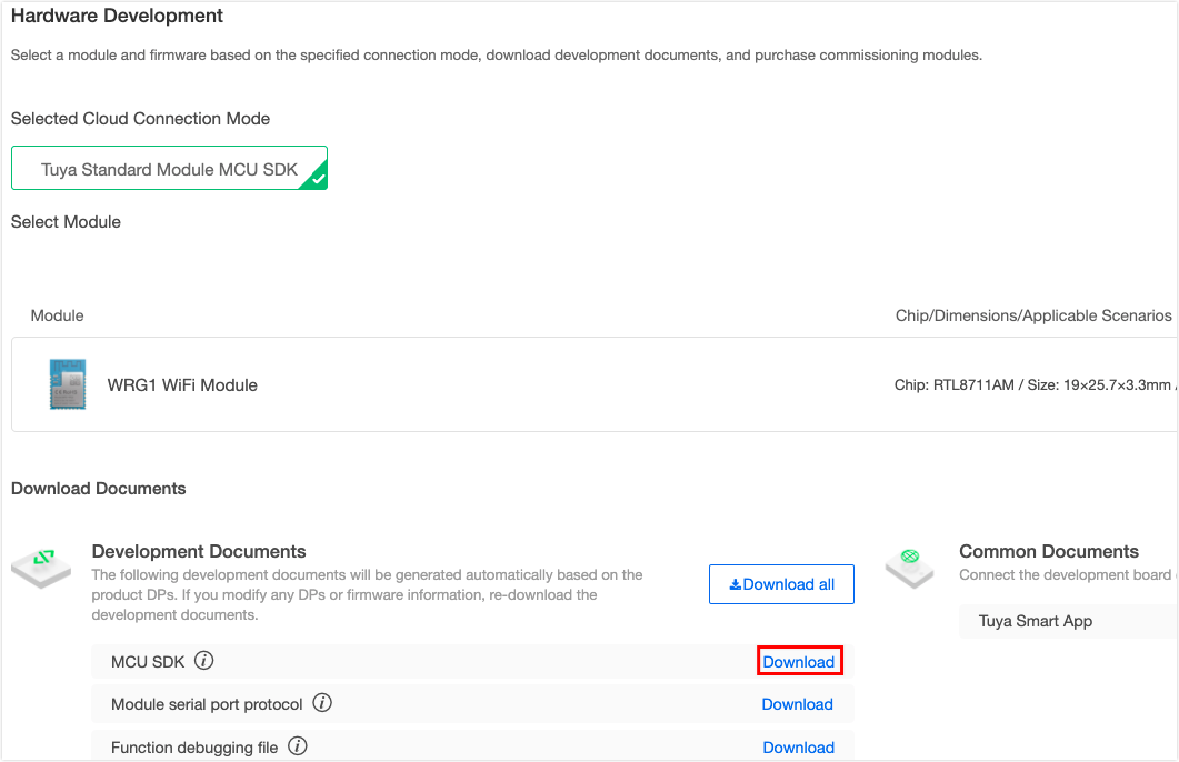
On the page of hardware development on the Tuya IoT Platform, after selecting the module and firmware, you can find the download link of the MCU SDK. For more information, see MCU Development for Gateway.
Note: MCU SDK will change with the product configuration. If you change the data point (DP) in the Function Definition or re-select the network module, download the MCU SDK again.
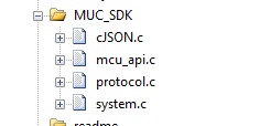
SDK directory structure
The directory structure of the MCU SDK is as follows:
|- gateway_mcu_sdk
  | |- system.c
  | |- system.h
  | |- mcu_api.c
  | |- mcu_api.h
  | |- protocol.c
  | |- protocol.h
  | |- cJSON.c
  | |- cJSON.h
  | |- wifi.h
  | |- readme.txt
Some documents are described as follows.
| Executable file | Header file | Description |
|---|---|---|
| mcu_api.c | mcu_api.h | Include Wi-Fi functions. You can call them as needed. |
| protocol.c | protocol.h | Protocol file, including data processing functions. Modify these two files according to project requirements. |
| system.c | system.h | The implementation of serial communication protocol. |
| wifi.h | Wi-Fi macro definition | |
| cJSON.c | cJSON.h | Include JSON parsing and combination processing functions. |
SDK migration
SDK requirements for MCU hardware resources:
- 4-byte flash.
- RAM size is about 100 bytes, which is related to DP data length. If the OTA function is configured, RAM must be greater than 260 bytes.
- 9-level nested function is adopted.
If your device has insufficient resources, you can connect to the serial port protocol. For more information, see Serial Port Protocol. The functions in the SDK package can act as references.
SDK migration procedure
After you get the MCU SDK, follow the steps below to complete the SDK migration.
- Program the MCU and migrate SDK files.
- Confirm the macro definition of
protocol.h. - Migrate the
protocol.cfile and call the function. - Complete the function of reporting and sending DP.
- Complete network pairing and indicator functions.
- Improve the production test features.
Step 1: Program the MCU and migrate SDK files
In your current project, add the .c and .h files in the mcu_sdk folder, and add the corresponding header file reference path. Initialize the MCU peripherals, including serial port (data communication), external interrupt (button), timer (with the indicator flickering), and more.
Step 2: Confirm the macro definition of protocol.h
Query product information
-
PRODUCT_KEYis the macro definition of a product ID (PID), which is the unique identifier of each product. Make sure that the code is consistent with the value displayed on the Tuya IoT Platform. If not, download the SDK again on the Hardware Development page of the product development process.
-
MCU_VERis the software version,1.0.0by default. If the MCU needs an OTA feature, a newer MCU version number shall be added. -
CONFIG_MODEis the network pairing mode. Usually, the default mode is selected.#ifndef __PROTOCOL_H_ #define __PROTOCOL_H_ /****************************************************************************** Product information configuration ******************************************************************************/ /****************************************************************************** 1. Modify product information ******************************************************************************/ // PID information, automatically filled by the server. #define PRODUCT_KEY "gqkvyygeah6rdhbv" // The 16-digit unique ID of the product after it is created on the Tuya IoT Platform. #define MCU_VER "1.0.0" // The software version, which is used to update MCU firmware. It must be modified after MCU is updated. // Select the pairing mode. The default is CONFIG_MODE_DEFAULT, and only one mode can be chosen from the three modes. #define CONFIG_MODE CONFIG_MODE_DEFAULT // Default pairing mode //#define CONFIG_MODE CONFIG_MODE_LOWPOWER // Low power pairing mode //#define CONFIG_MODE CONFIG_MODE_SPECIAL // Special pairing mode // The special configuration with both Wi-Fi Easy Connect and AP modes. If this macro definition is not used, switch between Wi-Fi Easy Connect mode and AP mode. //#define CONFIG_MODE_CHOOSE 0 // Enable AP and Wi-Fi Easy Connect pairing at the same time, with no need to switch. The network status is 0x06. //#define CONFIG_MODE_CHOOSE 1 // Only use AP pairing mode.
Confirm whether MCU supports firmware updates
To support MCU firmware OTA updates, enable this macro. After this macro is enabled, select the firmware update package size.
/******************************************************************************
 Enable the macro to support MCU firmware update or sub-device update. ******************************************************************************/
 //#define SUPPORT_MCU_FIRM_UPDATE // Enable MCU firmware update function, which is disabled by default.
#ifdef SUPPORT_MCU_FIRM_UPDATE
 // Select firmware update package size. 0x00: 256 bytes (default), 0x01: 512 bytes, 0x02: 1024 bytes.
#define PACKAGE_SIZE                     0x00      // The size of a single firmware update package is 256 bytes.
//#define PACKAGE_SIZE                     0x01      // 512 bytes
//#define PACKAGE_SIZE                     0x02      // 1024 bytes
#endif
MCU update
To implement an OTA update, it is necessary to manage the MCU flash and divide the code into bootloader and application code. Only the application code is transferred by OTA. After the firmware update package is transferred, the bootloader will guide the MCU to execute the new application code, update the MCU firmware, and execute it successfully.
- The bootloader code must be flashed to the start address of the MCU by default, which is generally
0x08000000. Make sure that every time the MCU is powered on or reset, the bootloader is executed first. - The flashing start address of the application code can be shifted backward according to the size of the bootloader, such as
0x00000200.
To perform an OTA update, first, compile the new .bin file. Note that the version number (MCU_VER) in the protocol.h file must be renewed by one version. Refer to the following code #define MCU_VER "1.0.1" to verify the update success.
#ifndef __PROTOCOL_H_
#define __PROTOCOL_H_

/******************************************************************************
                            Product information configuration ******************************************************************************/
/******************************************************************************
                            1. Modify product information ******************************************************************************/
// PID information, automatically filled by the server.
#define PRODUCT_KEY "gqkvyygeah6rdhbv"    // The 16-digit unique ID of the product after it is created on the Tuya IoT Platform.

#define MCU_VER "1.0.1"                                   // The software version, which is used to update MCU firmware. It must be modified after MCU is updated.

// Select the pairing mode. The default is CONFIG_MODE_DEFAULT, and only one mode can be chosen from the three modes.
#define CONFIG_MODE     CONFIG_MODE_DEFAULT             // Default pairing mode
//#define CONFIG_MODE CONFIG_MODE_LOWPOWER // Low power pairing mode
//#define CONFIG_MODE     CONFIG_MODE_SPECIAL  // Special pairing mode
Once the new version of the .bin file is generated, you can configure the OTA update on the Tuya IoT Platform. For detailed steps, see Select and Change the Firmware Version.
Next, perform the OTA update according to the selected update method. After the firmware update is completed, the MCU restarts and executes the new firmware code. During the OTA update, all data reporting is stopped. After the Tuya module has sent all update packages, it resends the command 0x01. The MCU must reply with the updated MCU software version number in the product information within one minute. The version number must be consistent with that configured on the Tuya IoT Platform.
There are four types of MCU updates:
-
App notification update: Each time you enter the app, the app receives an update prompt. You can choose to update or not.
-
App silent update: There is no update prompt on the app. The module detects update automatically within one minute after the firmware is powered on, and automatically pulls the update package if the latest version update package is found. After the first power-on, the module detects whether there is an update package in the cloud every 24 hours.
-
App forced update: There is an update prompt on the app. Users are required to update the device before they can continue to use it.
-
App detects updates: There is no update prompt on the app. You must click check for updates on the app. If the latest version firmware is available, an update prompt will appear.
Define transceiving buffer
Modify the buffer size. According to the DP definition, the serial port transceiving buffer must be greater than the longest DP data length. The default size is 24 bytes. If the OTA function is configured, the buffer must be greater than 260 bytes. The size of the receiving queue can be appropriately reduced if RAM is insufficient.
/******************************************************************************
                                        3. Define transceiving buffer
                                 Define the size of the transceiving buffer ******************************************************************************/
#ifndef SUPPORT_MCU_FIRM_UPDATE
#define WIFI_UART_QUEUE_LMT 16 // Data receiving queue size, which can be reduced if the RAM of the MCU is not enough.
#define WIFI_UART_RECV_BUF_LMT 128 // The size of the serial data receiving buffer, which can be reduced if the RAM of the MCU is not enough.
#define WIFI_DATA_PROCESS_LMT 128 // The size of the serial data processing buffer. According to the DP data size, it is recommended to be greater than 24 bytes.
#else
#define WIFI_UART_RECV_BUF_LMT 128 // The size of the serial data receiving buffer, which can be reduced if the RAM of the MCU is not enough.

// When the single update package size is 256 bytes, 512 bytes, or 1024 bytes, the buffer size must be increased.
// Firmware update buffer, requiring a large buffer
#define WIFI_DATA_PROCESS_LMT          300              // The size of a single package is 256 bytes.
//#define WIFI_DATA_PROCESS_LMT        600              // The size of a single package is 512 bytes.
//#define WIFI_DATA_PROCESS_LMT        1200             // The size of a single package is 1024 bytes.
#endif

#define WIFIR_UART_SEND_BUF_LMT 128 // Determine it according to the user's DP data size. The user can modify it according to the actual situation.
Define how the module works (required)
-
If the pairing button and LED indicator are connected to the MCU, the frequently-used working mode of coordinated processing of the module and MCU is selected.
definemust be kept in the commented status./****************************************************************************** 4: Define how the module works Self-processing mode of the module: The Wi-Fi indicator and Wi-Fi reset button are connected to the Wi-Fi module (enable the `WIFI_CONTROL_SELF_MODE` macro). Define `WF_STATE_KEY` and `WF_RESET_KEY` correctly. Self-processing mode of the MCU: The Wi-Fi indicator and Wi-Fi reset button are connected to the Wi-Fi module (disable the `WIFI_CONTROL_SELF_MODE` macro). The MCU calls the `mcu_reset_wifi()` function in the `mcu_api.c` file where it needs to handle the reset Wi-Fi, and can call the `mcu_get_reset_wifi_flag()` function to return the Wi-Fi reset result. Alternatively, call the `mcu_set_wifi_mode` (`WIFI_CONFIG_E` mode) function in the `mcu_api.c` file to set the Wi-Fi mode, and call the `mcu_get_wifi_work_state()` function to return the Wi-Fi setting result. ******************************************************************************/ //#define WIFI_CONTROL_SELF_MODE // Wi-Fi self-processing button and LED indicator. If the MCU is connected to an external button or LED indicator, disable the macro. -
Enable the macro if the Wi-Fi indicator and buttons are connected to the Wi-Fi module (self-processing working mode of the module).
#define WIFI_CONTROL_SELF_MODE -
According to the actual hardware connection, fill in the GPIO pins connected to the indicators and buttons in the following two lines.
// For example, if PORT is 2 and pin is 3, it means `GPIO C_3` is selected.
#ifdef WIFI_CONTROL_SELF_MODE // Module self-processing
#define WF_LED_PORT 0 // PORT of the Wi-Fi status indicator. Valid range: 0 to 3, representing A to D in turn. Set it according to the actual GPIO pin.
#define     WF_LED_PIN             0  // PIN of the Wi-Fi status indicator. Valid range: 0 to 7. Set it according to the actual GPIO pin.
#define     WF_RESERT_KEY_PORT     0 // PORT of the reset button. Valid range: 0 to 3, representing A to D in turn. Set it according to the actual GPIO pin.
#define     WF_RESERT_KEY_PIN      0 // PIN of the reset button. Valid range: 0 to 7. Set it according to the actual GPIO pin.
#endif
Confirm whether MCU supports time sync
To support time sync, enable this macro. Implement the code in the mcu_write_rtctime in the Protocol.c file. After the Wi-Fi module is correctly connected to the network, the MCU can call the mcu_get_system_time() function to initiate the feature.
/******************************************************************************
                              Confirm whether MCU supports time sync
If necessary, enable this macro and implement the code in the `mcu_write_rtctime` in the `Protocol.c` file.
`mcu_write_rtctime` has the `#err` message. You must delete this message after you complete these functions.
After the Wi-Fi module is correctly connected to the network, the MCU can call the `mcu_get_system_time()` function to initiate the feature.
******************************************************************************/
 //#define SUPPORT_MCU_RTC_CHECK // Enable time sync feature
Confirm whether to enable the Wi-Fi production test feature (enable)
To ensure the final mass production efficiency and quality, it is recommended to enable this macro. For the implementation of specific test features, see Step 6 production test.
/******************************************************************************
                        Confirm whether MCU supports Wi-Fi functional test
If necessary, enable this macro. The MCU calls `mcu_start_wifitest` in the `mcu_api.c` file where the Wi-Fi functional test is required. View the test result in the `wifi_test_result` function of the `protocol.c` file.
`wifi_test_result` has the `#err` message. You must delete this message after you complete these functions.
******************************************************************************/
 #define WIFI_TEST_ENABLE // Enable Wi-Fi test feature (scan the specified router)
Step 3: Migrate the protocol.c file and call the function
-
Include the
wifi.hfile to the folder where Wi-Fi related files are required, such asmain.c.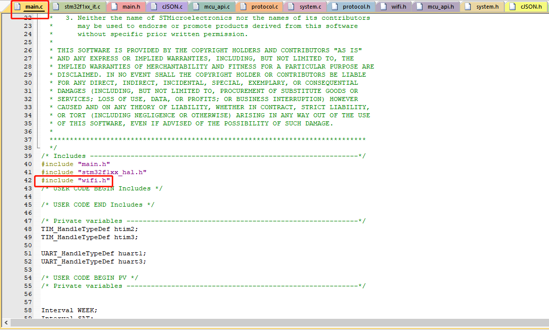
-
Call the
wifi_protocol_init()function in themcu_api.cfile after the MCU peripherals are initialized.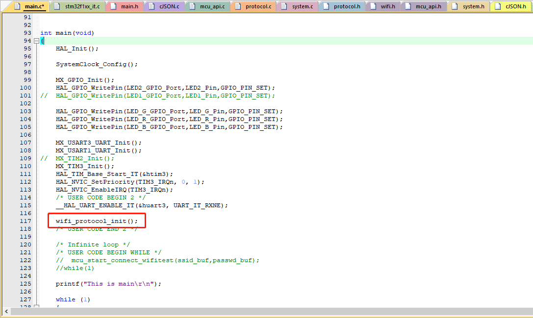
-
Fill in the single-byte sending function of the MCU serial port in the
uart_transmit_outputfunction in theprotocol.cfile, and delete#error. For example,/** * @brief The data to be sent by the serial port * @param[in] {value} 1-byte data to be sent by the serial port * @return Null */ void uart_transmit_output(unsigned char value) { #error "Fill in the MCU serial port sending function and delete this line" UART3_SendByte(value); /* // Example: extern void Uart_PutChar(unsigned char value); Uart_PutChar(value); // Serial port sending function */ } -
Call the
uart_receive_inputfunction in themcu_api.cfile in the serial port receiving interrupt service function, and pass in the received characters as a parameter. For example,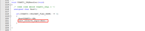
-
After the MCU enters the
whileloop, thewifi_uart_service()function in themcu_api.cfile is called.
The sample code structure inmain.cis as follows:include "wifi.h" … void main(void) { wifi_protocol_init(); … while(1) { wifi_uart_service(); … } }Note: The MCU must directly call the
wifi_uart_service()function inmcu_api.cin thewhileprogram. After the program is initialized successfully, it is recommended not to close the serial port interrupt. If the interrupt must be closed, the closed period must be short. Closing the interrupt will cause serial data packet loss. Do not call the reporting function during the interrupt.
Step 4: Complete the function of reporting and sending DP
Report all DP data
After restarted or paired again, the Wi-Fi module actively sends a status query command. The MCU must report all the DP status of the device to the Wi-Fi module for synchronization.
-
Open
protocol.cand find the functionall_data_update(void). -
Enter all the initial values of DPs to be reported in the corresponding reporting function to provide the panel with the initial values displayed at startup.
Note: Do not call the
all_data_update()function. This function will be called actively at a specific time.
Report single DP data
When the status of a single DP changes, the MCU must actively report it, and the app updates the display content. The report format is mcu_dp_xxxx_updata (DPID_X, n, sub-device ID, sub-device ID length). DPID_X is the changed DP, n represents the value of the DP, and the sub-device ID is a string. When the sub-device ID is 0000, it means the DP of the gateway. all_data_update() functions can be called individually. For example,
mcu_dp_bool_update(DPID_SWITCH,1,"0000",strlen("0000")); // Boolean type data report
mcu_dp_value_update(DPID_TEMPER_SET,25,"1234",strlen("1234")); // Value type data report
mcu_dp_string_update(DPID_DAY,"1234",4,"5678",strlen("5678")); // String type data report
DP data sending processing function
In the protocol.c file, each sendable DP has an individual sent data processing function. The format is dp_download_xxx_handle(), where xxx is the DP that can be sent. After the function parses the DP, the MCU must complete the logic control in the corresponding position. Take the received tamper alarm DP data as an example:
/*****************************************************************************
Function name: dp_download_temper_alarm_handle
Function description: processing function for DPID_TEMPER_ALARM
Input parameters: value indicates data source
                               length indicates data length
Return parameters: Return SUCCESS on success, and return ERROR on failure
Instruction: Regarding the data for reporting and sending, the processing results must be reported to the app after processing
*****************************************************************************/
static unsigned char dp_download_temper_alarm_handle(const unsigned char value[], unsigned short length, unsigned char *sub_id_bur, unsigned char sub_id_len)
 {
 // Example: The current DP type is Boolean
 unsigned char ret;
 // 0: off/1: on
 unsigned char temper_alarm;

 temper_alarm = mcu_get_dp_download_bool(value,length);
 if(temper_alarm == 0)
  {
    // The off status of the switch
    temper_alarm_ctrl(ON);
  }
  else
  {
    // The on status of the switch
    temper_alarm_ctrl(OFF);
  }

 // Feedback after DP data is processed
ret = mcu_dp_bool_update(DPID_TEMPER_ALARM, temper_alarm, sub_id_buf, sub_id_len);
  if(ret == SUCCESS)
    return SUCCESS;
  else
    return ERROR;
 }
temper_alarm_ctrl(ON) and temper_alarm_ctrl(OFF) are MCU control switch functions to complete specific actions. When the device status changes are not triggered by the app, the MCU needs to call mcu_dp_bool_update(DPID_TEMPER_ALARM,temper_alarm,sub_id_buf,sub_id_len); to upload the real-time status of the DP to form feedback. The receiving processing function usually has automatically called this function.
Step 5: Complete network pairing and indicator functions
Note: If your module is in self-processing mode, you do not need to implement functions in this section.
After the migration protocol is successful, the network pairing commands and indicators need to be perfected to allow pairing. For coordinated processing of the module and MCU, pairing trigger method and indication method can be determined according to the actual situation. Usually, it is triggered by pressing a button and indicated with a quickly or slowly flickering LED.
Two Wi-Fi pairing modes are supported:
- Wi-Fi Easy Connect: Easy to operate, usually indicated by a quickly flickering indicator.
- AP mode: Reliable pairing, usually indicated by a slowly flickering indicator.
Pairing commands
The pairing commands can be implemented with two functions: mcu_reset_wifi() and mcu_set_wifi_mode() in mcu_api.c. It is called in the button processing function after the button is pressed for pairing.
Reset the Wi-Fi module after calling mcu_reset_wifi(). All previous pairing information will be cleared after reset, and the module will wait for pairing. When the module already waits for pairing, calling mcu_reset_wifi() will switch the pairing mode between AP mode and Wi-Fi Easy Connect.
mcu_set_wifi_mode() parameter: SMART_CONFIG and AP_CONFIG. After calling, clear the pairing information and enter Wi-Fi Easy Connect mode or AP mode. Like mcu_reset_wifi(), the function can be selected and called as needed.
Pairing guide
Usually, call the mcu_get_wifi_work_state() function in while(1) to return the Wi-Fi status, and write the corresponding indicator mode according to the Wi-Fi status.
| Status | Description | Status value | LED |
|---|---|---|---|
| Status 1 | Wi-Fi Easy Connect configuration status | 0x00 | Flicker quickly at an interval of 250 ms |
| Status 2 | AP configuration status | 0x01 | Flicker slowly at an interval of 1,500 ms |
| Status 3 | Wi-Fi has been configured, but not connected to the router | 0x02 | Off |
| Status 4 | Wi-Fi has been configured, and connected to the router | 0x03 | Always on |
| Status 5 | Connected to the router and the cloud | 0x04 | Always on |
| Status 6 | The Wi-Fi device is in the low power mode | 0x05 | Off |
Call the mcu_get_wifi_work_state() function to get the connection status. The function structure is as follows:
void main(void)
{
	...
	while(1)
	{
        	...
		switch(mcu_get_wifi_work_state())
		{
			case SMART_CONFIG_STATE:
			  // The LED flickers quickly in Wi-Fi Easy Connect configuration status. You need to implement this function.
			break;
			case AP_STATE:
			  // The LED flickers slowly in AP configuration status.
			break;
			case WIFI_NOT_CONNECTED:
			  // Wi-Fi configuration is completed and the router is being connected. The LED is always off.
			break;
			case WIFI_CONNECTED:
			  // The router is connected successfully. The LED is always on.
			break;
			default:break;
		}
		...
	}
}
Step 6: Improve the production test features
The default test process is to scan the designated router. You can also customize a test process. This process can be repeated.
- Prepare a router, or use a computer or mobile phone to create a Wi-Fi hotspot.
- Change the Wi-Fi network name to
tuya_mdev_testand set the frequency to 2.4 GHz. - Trigger the device pairing process. The test can be triggered with a button. For example, press and hold a button for three seconds. It can also be triggered in other ways.
- The MCU calls the
mcu_start_wifitest()function in themcu_api.cfile. The MCU sends the command of scanning the specified router to the gateway. - The gateway scans the Wi-Fi hotspot named
tuya_mdev_test, and then returns the result to the MCU. - The MCU parses the returned result to determine whether the test is passed.
Data communication between MCU SDK and the module
For the description of the data frame format, see the frame format chapter of the Serial Port Protocol.
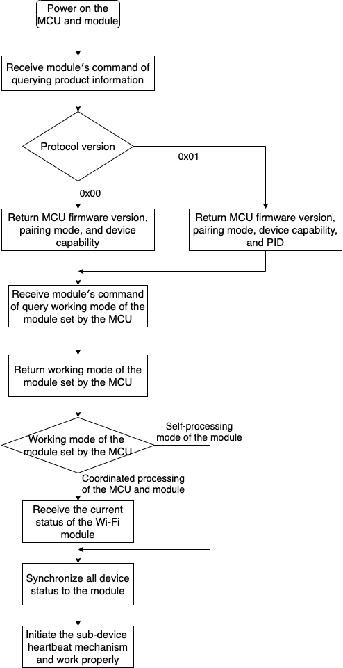
Initialization communication
After the MCU and the module are powered on, some initial configuration needs to be performed. During this period, it is necessary to verify whether the MCU and the module work properly, whether the communication connection is successful, how to get the data required for module activation, and how the module gets the working mode.
Query product information
After the device is powered on, the module needs to query information such as the MCU firmware version, pairing mode, device capabilities, and PID.
- Version number: It is used to verify whether the OTA update is successful.
- Pairing mode: It is used to select the pairing mode of the module, including default pairing, low-power pairing, and special pairing.
- Device capability: According to the application scenario of the gateway, select local group, local scenario, gateway with function DP, Bluetooth Mesh, support for MCU update, group control command with sub_id, and other options.
- PID: It is used for product activation. You can determine whether the MCU will return the PID according to the version field of the frame data sent by the module. Version
0x00means no reply is required, and0x01means reply is required. The PID is returned by default.
Query working mode of the MCU and the module
Set the working mode of the module, select the coordinated processing mode of the MCU and the module, or the self-processing mode of the module. Select the mode according to the hardware connection position of the Wi-Fi network status indicator and the module reset button.
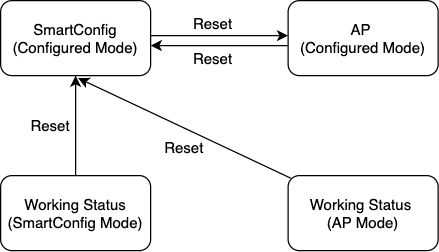
The working mode of the module includes Wi-Fi working status indication and Wi-Fi network reset. There are two cases:
-
Coordinated processing by the MCU and the module: The module notifies the MCU of the current working status of the module through the serial port, and MCU displays the working status of the module. The MCU detects the reset requirement of the module, and through the serial port, notifies the module to reset.
-
Self-processing by the module: The working status of the Wi-Fi module is displayed through the Wi-Fi GPIO pin to drive the LED indicator. The Wi-Fi module is reset by detecting the GPIO input pin.
Reset Wi-Fi in the self-processing mode: Wi-Fi detects the low level of GPIO input pin for more than five seconds to trigger Wi-Fi reset. The GPIO pins used by the indicators and buttons are configured by the following commands.
Things to note
-
To avoid unpredictable problems, it is recommended that data communication, such as DP sending and reporting and OTA update, should be carried out after the initialization is completed.
-
After the device is powered on again, the data transmission must be performed after the entire initialization of the device is completed.
Data transmission process
Is this page helpful?
YesFeedbackIs this page helpful?
YesFeedback


