Smart Pet-Feeding Way
Overview
Last year, when the epidemic broke out, many areas across the country closed down cities and communities, separating the beloved pet from the pet in another place. When encountering a prepared feces shovel officer, the masters can barely make the day. Those who are not prepared can only live by eating cat litter and eating garbage, and even some little ones are starved to death.
After the epidemic eased, in order to avoid such incidents from happening again, and to liberate lazy shit scavengers, the demand for automatic litter boxes, automatic feeders, and automatic water feeders continued to increase. Data shows that after the epidemic, automatic litter boxes have increased by 879%, automatic water feeders have increased by 120%, and automatic feeders have more than doubled. After all, the master is the boss of the family, and he wants to eat and drink, but also to pull well.
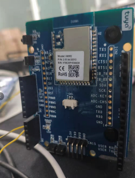
The DIY automatic feeding device is planned by the actual combat camp of [Pet Feeder] launched by Tuya Smart, and a Tuya Sandwich Development Kit is provided. Developers need to prepare the MCU control board and motor and other components by themselves. The WiFi module defaults to the transparent transmission mode, which is only responsible for data forwarding, not data processing, so we only need to prepare the MCU for data processing and peripheral control.
Materials
Wi-Fi MCU Communication Board
Count:1Tuya Sandwich Evaluation Kit
H-Bridge DC Motor Drive Board
Count:1Tuya Sandwich Evaluation Kit
Steps
Tuya IoT Platform
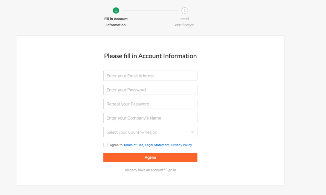
Go to the Tuya Smart Development Platform to register a developer account
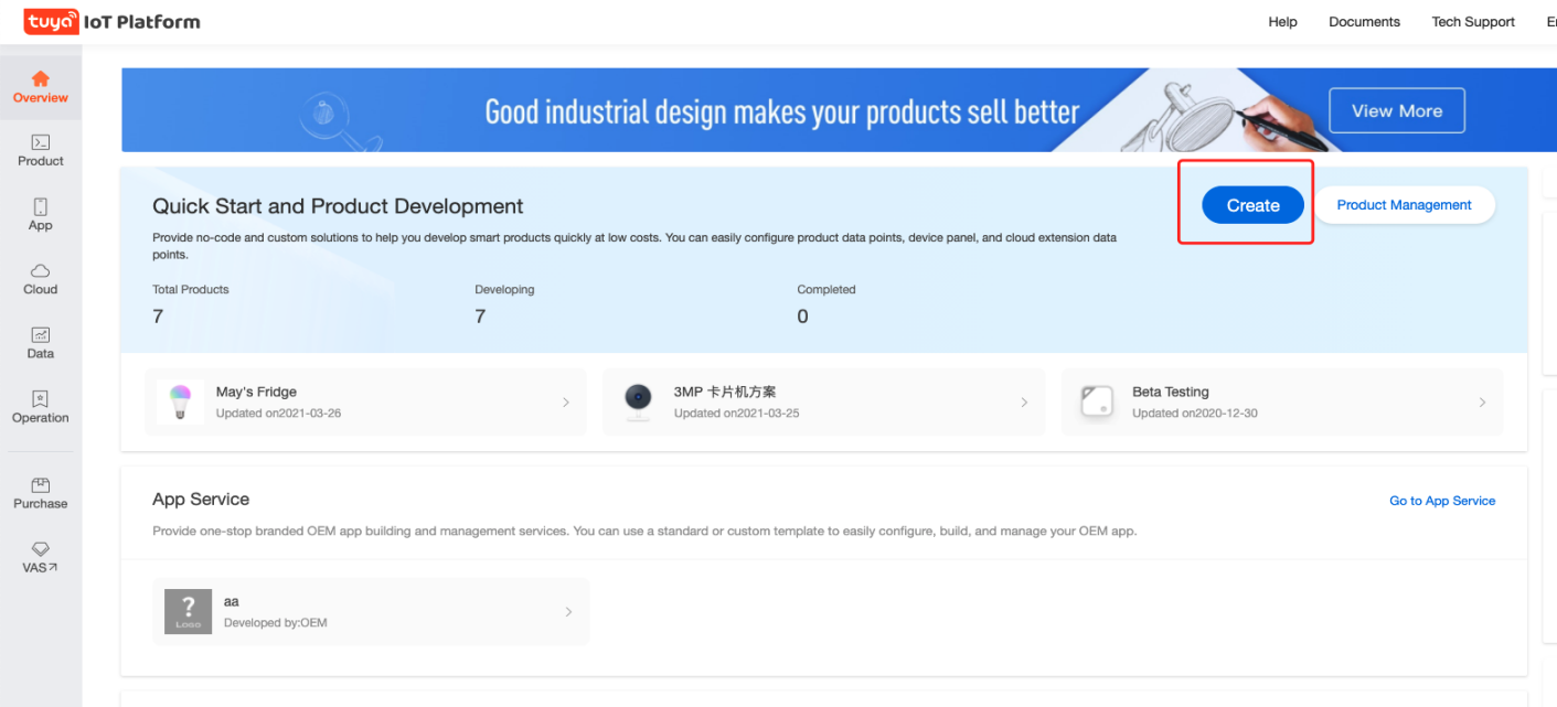
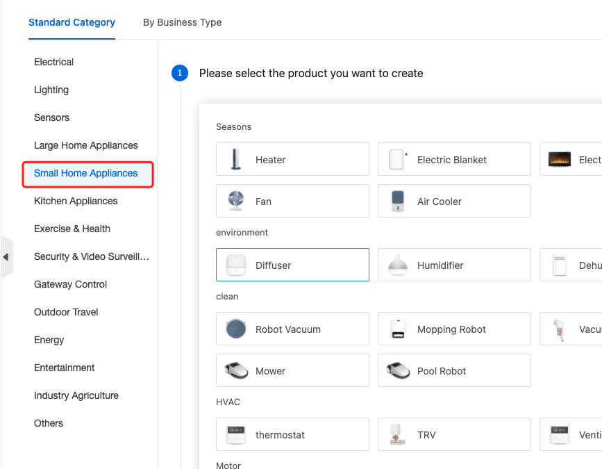
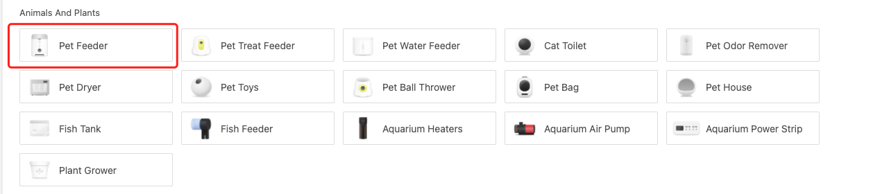
Click Create Product Find [pet feeder] in the category of small appliances
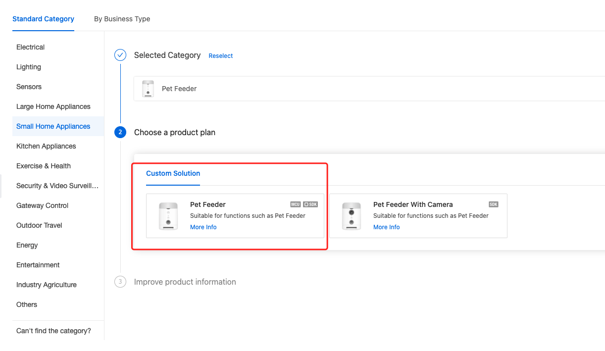
Use MCU SDK solution to improve product information
After creating the product, you can add standard functions and choose by yourself
The hardware development is configured as follows
For more specific configuration of the above steps, please refer to Tuya IOT platform product creation process
After the product is created, download the development materials. It is recommended to download all of them. The content of the MCU SDK will vary according to the standard functions you choose. For convenience, you can consider as many functions as possible when selecting functions. Of course, even If you don't choose one, the SDK also opens up the functions of each function, but they are blocked and you can let them go.
Function Debugging
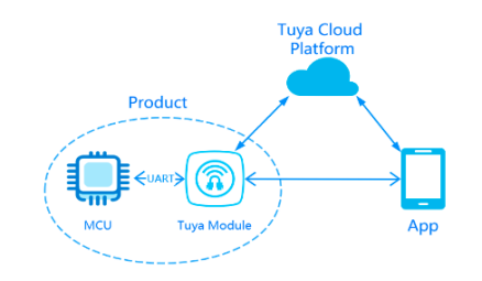
Communication schematic diagram of MCU docking scheme:
Smart Pet-Feeding Way Last Updated on: 2021-04-02 19:35:45 21 Xiaopaotang Overview Last year, when the epidemic broke out, many areas across the country closed down cities and communities, separating the beloved pet from the pet in another place. When encountering a prepared feces shovel officer, the masters can barely make the day. Those who are not prepared can only live by eating cat litter and eating garbage, and even some little ones are starved to death.
After the epidemic eased, in order to avoid such incidents from happening again, and to liberate lazy shit scavengers, the demand for automatic litter boxes, automatic feeders, and automatic water feeders continued to increase. Data shows that after the epidemic, automatic litter boxes have increased by 879%, automatic water feeders have increased by 120%, and automatic feeders have more than doubled. After all, the master is the boss of the family, and he wants to eat and drink, but also to pull well.
The DIY automatic feeding device is planned by the actual combat camp of [Pet Feeder] launched by Tuya Smart, and a Tuya Sandwich Development Kit is provided. Developers need to prepare the MCU control board and motor and other components by themselves. The WiFi module defaults to the transparent transmission mode, which is only responsible for data forwarding, not data processing, so we only need to prepare the MCU for data processing and peripheral control.
Materials Hardware (3) Wi-Fi MCU Communication Board Wi-Fi MCU Communication Board Count:1 Tuya Sandwich Evaluation Kit
H-Bridge DC Motor Drive Board H-Bridge DC Motor Drive Board Count:1 Tuya Sandwich Evaluation Kit
DC-DC power supply board DC-DC power supply board Count:1 Tuya Sandwich Evaluation Kit
Steps Tuya IoT Platform Go to the Tuya Smart Development Platform to register a developer account Click Create Product Find [pet feeder] in the category of small appliances Use MCU SDK solution to improve product information After creating the product, you can add standard functions and choose by yourself The hardware development is configured as follows For more specific configuration of the above steps, please refer to Tuya IOT platform product creation process
After the product is created, download the development materials. It is recommended to download all of them. The content of the MCU SDK will vary according to the standard functions you choose. For convenience, you can consider as many functions as possible when selecting functions. Of course, even If you don't choose one, the SDK also opens up the functions of each function, but they are blocked and you can let them go.
Function debugging Communication schematic diagram of MCU docking scheme:
- WiFi module debugging The file finally downloaded in the previous step is as shown in the figure below. In the first step, we open the Tuya debugging assistant
Connect the serial port 1 of the WiFi communication board to the usb-ttl, and connect it to the computer. It must be the serial port 1. The serial port 0 is to view the logo of the module itself, and open the Tuya debugging assistant. Select MCU simulation, the debugging assistant is equivalent to the MCU at this time, which can communicate with the WiFi module, which can be used to debug the WiFi module. Select the serial port, the baud rate defaults to 9600. The function point debugging file selects the previously downloaded json file. The initial configuration keeps the default, click to start debugging. If you receive the following data, it means that the connection between the module and the assistant is normal, and you can start debugging.
At this time, we download the Tuya Smart APP, choose to add a device after registration, find the pet feeder in the small household appliances, and select the 2.4G WiFi network, enter password, proceed to next step.
At this time, click smart distribution network in the module debugging assistant, and click next on the mobile phone. After the network configuration is successful, you will see the corresponding information in the mobile phone APP and the debugging assistant at the same time. After the connection is successful, it will periodically send heartbeat packets to maintain the connection.
At this point, the WiFi module configuration is completed, and the modified network information will be stored inside the WiFi module, and the network will be automatically connected to the next power-on. If you change the network environment, you need to reset the network again. Now, you can test the data report of the relevant DP points in the DP CMD, and observe whether there is any data report and issuance.
- MCU debugging After the WiFi module is debugged, we need to debug our main control, which is the MCU, which is STM32F103 in my case. Before debugging the MCU, we need to transplant the SDK first, and transplant the SDK downloaded before to our STM32 project.
(1) foundation project creation: Before transplanting, we need to prepare an empty project, and only need to add a serial port driver to the project.
#ifndef __USART_H
#define        __USART_H


#include "stm32f10x.h"
#include <stdio.h>

// Serial Port 1 - USART1
#define  DEBUG_USARTx                   USART1
#define  DEBUG_USART_CLK                RCC_APB2Periph_USART1
#define  DEBUG_USART_APBxClkCmd         RCC_APB2PeriphClockCmd
#define  DEBUG_USART_BAUDRATE           9600

// USART GPIO Pin Definition
#define  DEBUG_USART_GPIO_CLK           (RCC_APB2Periph_GPIOA)
#define  DEBUG_USART_GPIO_APBxClkCmd    RCC_APB2PeriphClockCmd

#define  DEBUG_USART_TX_GPIO_PORT         GPIOA
#define  DEBUG_USART_TX_GPIO_PIN          GPIO_Pin_9
#define  DEBUG_USART_RX_GPIO_PORT       GPIOA
#define  DEBUG_USART_RX_GPIO_PIN        GPIO_Pin_10

#define  DEBUG_USART_IRQ                USART1_IRQn
#define  DEBUG_USART_IRQHandler         USART1_IRQHandler


void USART_Config(void);
void Usart_SendByte( USART_TypeDef * pUSARTx, uint8_t ch);
#endif /* __USART_H */
The Content you are browsing is publicized by registered users of Tuya DeveloperPlatform, and the copyright of which belongs to the original author. Tuya DeveloperPlatform does not own the copyright of the Content, nor undertake any liability. Tuya Developer Platform makes no representations or warranties that the Content is not in violation or infringement of any right. You should acknowledge and understand that your reproduction, adaptation, transmission, or other action with respect to the Contentshall conform to all applicable laws and regulations and shall acquire the requiredlicense of the related licensor. All the consequences (including but not limited to infringement, breach of contract, damage, disputes with a third party, etc.) resulted therefrom shall be borne by yourself. You can refer to the 《Tuya Developer Platform User Agreement》for the terms and conditions relating to the intellectual property rights of Content. If you find any suspected infringing content, please contact the Platform immediately to report and send relevant evidence. Once verified, the Platform will immediately delete the suspected infringing content.


