High-end Pet Feeder

Overview
High-end modules often only need simple development---Tuya Sandwich Pet Feeder Record The pet feeder is based on the Tuya module connected to the cloud + STM32 main control, the end-user can use the mobile phone APP control/voice control, the main function is feeding automation.
Steps
Development process
Development process The first stage: graffiti module
- Click Create Product, find [Small Appliances]-[Pet Feeder], select [wifi] communication protocol, fill in the product name, and create the product. https://smartapp.tuya.com/s/p?
- Submit the development plan according to the "Sandwich Development Kit Receiving Process": https://shimo.im/docs/qCgdXjVPYqjdDWj3/
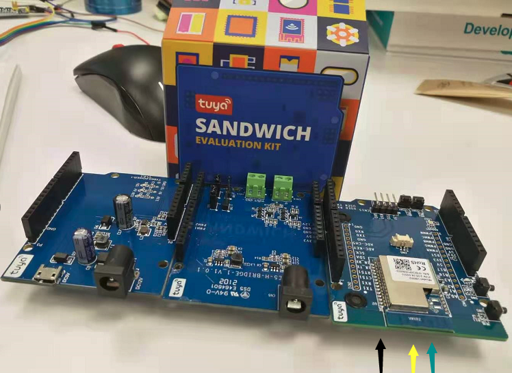
After the courier arrives, there are a total of 3 boards, which can be combined like piles of wood, which is the so-called sandwich
For R&D, you only need to use WIFI+voice. The two external two boards are power related and can be put together temporarily.
Direct PC external TTL serial port can supply power for work
Reset the board, you can see LOG in the serial port with 115200
Note: The LOG here is the template itself, just use the serial port assistant, or you don't need to read it.
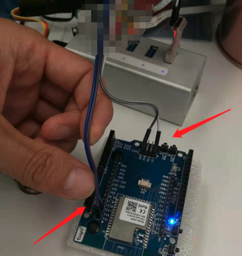
Now you need to use the Tuya debug assistant provided by Tuya to simulate the MCU to communicate with the board.
You need to unplug TXRX and plug it into the serial port UART1.
As shown in the picture above, power supply + serial port and you can play happily!
What can this board do?
Put it this way
Previously, M26, a networking module, only provided TCP/IP channels. Developers can complete the networking based on TCP/IP, transplant the MQTT protocol, and connect to the business protocol.
Later, the BC20 networking module appeared-it integrated the MQTT protocol internally, and threw AT commands for use. Developers can directly connect to the business protocol. !
Then there is a problem: business agreements are always artificially agreed and need to be modified. How can they be encapsulated in-house? How does Tuya solve it?
The production tools provided by Tuya are more advanced than family barrels.
When the product function is modified, this protocol will be modified, and the SDK and the JS file for PC tool debugging will be reproduced.
Clearing credentials didn't fix the issue.
Note: After modification, you need to configure the network again for the device.
Tip: The local WIFI is 5G. The notebook uses 360 free WIFI, which is actually not as good as the WIFI hotspot that comes with WIN1O! TY360WIFI TY360WIFI At this time, the mobile phone connects to the WIFI PC assistant to send network configuration instructions Press SW5 on the board and the LED flashes quickly <https://developer.tuya.com/cn/docs/iot/device-development/module/wifibt-dual-mode-module/wb-series-module/wb3s-module-datasheet?id=K9dx20n6hz5n4 id=K9hs0cj3lf0au>
Can be combined with LOG to see the process of protocol execution
The second stage: STM32 main control
Use cubeMX to build a simple project, only the following points are required
1---You need a UART to connect to the module because the code of the module is only 2 sentences, which is a serial port.
2---Suddenly I feel unnecessary because one serial port is enough. Other interfaces follow the product. I use an IO as the control of the LED, and a tim1 advanced timer PA8 as the pulse of the motor.
SDK is mainly serial programming
To
The third stage: STM32 main control + Tuya module
Because the previous PC has already simulated STM32, here is the real MCU.
Tests succeeded
To
The fourth stage: motor control
It’s easier to control LEDs. It’s actually not difficult to control stepper motors (mainly I use simple ones)
It is precisely because the motors are more complex and professional that motor drives have appeared on the market.
What we generally call controlling the motor is actually controlling the motor driver. On the wiring, the MCU pulls 3 wires to connect with the motor driver.
1----IO control direction 2-----IO control switch 3----pulse control motor speed
Wiring of the motor driver A The three wires on the top are connected to the main control B Two wires for power supply C The four wires for connecting the motor
After connecting it, it will be easier to control
Turn on the switch and send pulses to drive the motor.
The comparison output function of the advanced timer Set a comparison value and count up. When CNT = the set comparison value, an interrupt occurs and the level is switched.
At the same time, modify the next comparison value in the interrupt, so it keeps looping
The Content you are browsing is publicized by registered users of Tuya DeveloperPlatform, and the copyright of which belongs to the original author. Tuya DeveloperPlatform does not own the copyright of the Content, nor undertake any liability. Tuya Developer Platform makes no representations or warranties that the Content is not in violation or infringement of any right. You should acknowledge and understand that your reproduction, adaptation, transmission, or other action with respect to the Contentshall conform to all applicable laws and regulations and shall acquire the requiredlicense of the related licensor. All the consequences (including but not limited to infringement, breach of contract, damage, disputes with a third party, etc.) resulted therefrom shall be borne by yourself. You can refer to the 《Tuya Developer Platform User Agreement》for the terms and conditions relating to the intellectual property rights of Content. If you find any suspected infringing content, please contact the Platform immediately to report and send relevant evidence. Once verified, the Platform will immediately delete the suspected infringing content.


