Prototype a Self-Balancing Robot
Overview
Smart robots are helping us take care of many routine works thanks to our advanced AI and vision technologies. We can find their presence in shopping malls, restaurants, and hotels when we look for some information or wait for the delivery.
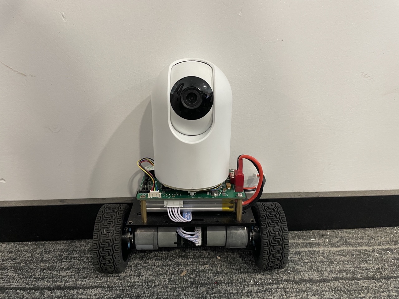
In this project, we will show you how to prototype a self-balancing robot that has multiple fascinating features like remote control, video talks, auto-follow, and obstacle avoidance. The compact body design allows the robot to be easily maneuvered through narrow spaces as well as on rough terrain.
Steps
Step 1: Hardware design
The following graph shows how the components communicate:
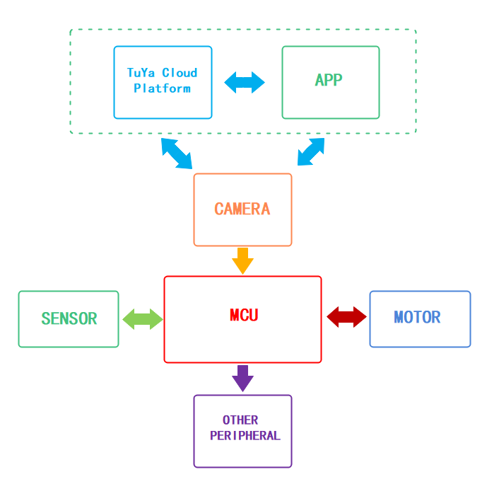
The prototype consists of the control unit, camera unit, and power unit. We will detail each unit in the following part.
Control unit
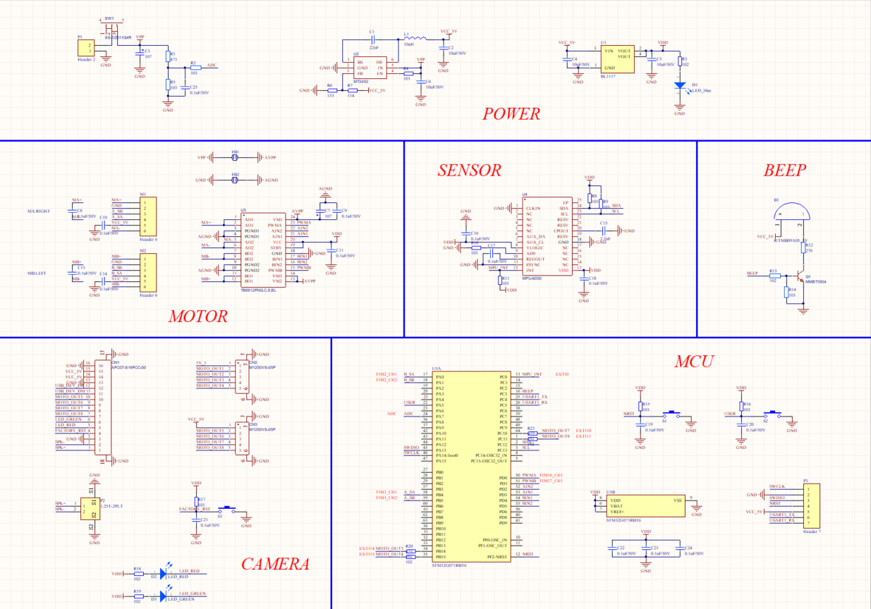
The schematic diagram is as follows.
MCU
We use STM32G071RBT6 as the microcontroller (MCU). The pin description is as follows.
NESTis the reset button.USERis the user-defined button that can be programmed as needed.A_SA,A_SB,B_SA, andB_SBcan operate in timer encoder interface mode. Connect them to the output pins of the Hall effect sensor on the two wheels. The encoder can convert the mechanical parameters such as angular displacement and angular velocity of the output shaft into corresponding electrical pulses and output them in digital quantity.PWMAandPWMBcan operate in timer PWM mode so that the rotation speed of the motor can be determined by the PWM timer output signal’s duty cycle.AIN1,AIN2,BIN1, andBIN2are GPIOs. We can make the motor go forward and reverse by applying either high or low level on these pins.MOTO_OUT3,MOTO_OUT4,MOTO_OUT7, andMOTO_ OUT8are external interrupt inputs, which can be used to implement robot control through a mobile app.ADCpin can be used to measure the battery voltage.BEEPpin can be used to control the buzzer.MPU_INTis external interrupt input. Connect the sensor to this pin to notify the MCU to read data.SCLandSDAare I2C pins. The MCU read sensor data through these two pins.SWDIOandSWCLKare used to download code to the MCU.USART1_TXandUSART1_RXare used for serial communication with external circuits.
Power
The Vpp input voltage is about 12V. The 12V supply voltage is provided to two motors directly and converted to 5V through the MT2492 step-down converter to power the camera unit and Hall effect sensor.
The MT2492 is a fully integrated, high–efficiency synchronous rectified step-down converter. Its efficiency can be up to 96%. This device operates at a high 600 kHz operating frequency and features 2A output current, 4.5V to 16V input voltage range, and over-current protection.
The converted 5V voltage will be further stepped down to 3.3V with a low-dropout (LDO) regulator to supply the MCU and other peripherals.
The AMS1117-33 is a positive LDO regulator and integrated with over-temperature protection and a current limiting circuit. It can output up to 1A current, support up to 12V input voltage, and regulate the output voltage to 3.3V, with an output voltage tolerance of less than 1%.
Motor
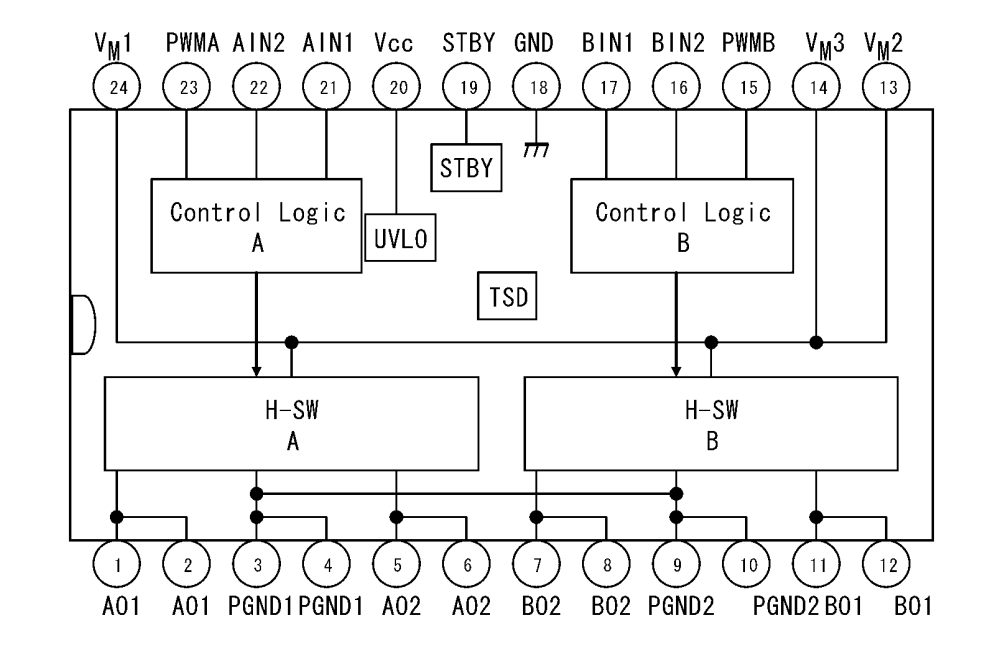
We use Toshiba’s TB6612FNG driver IC to control DC motors. TB6612FNG is a dual H-bridge, rated up to 3.2A peak and 1.2A continuous, 0.5Ω ON resistance, and a maximum voltage of 15V. It has a built-in thermal shutdown circuit and low voltage detecting circuit and accepts a PWM input with a frequency of up to 100 kHz.
TB6612FNG does not need a heat sink because it is much more efficient than the bipolar junction transistors (BJT) based drivers such as the L298N. It has a simple peripheral circuit, so adding a power supply filter capacitor can drive the motor.
The TB6612FNG has a pair of drivers and can control two motors independently. Connect the positive and negative terminals of the two motors to
MA+,MA-,MB+, andMB-respectively.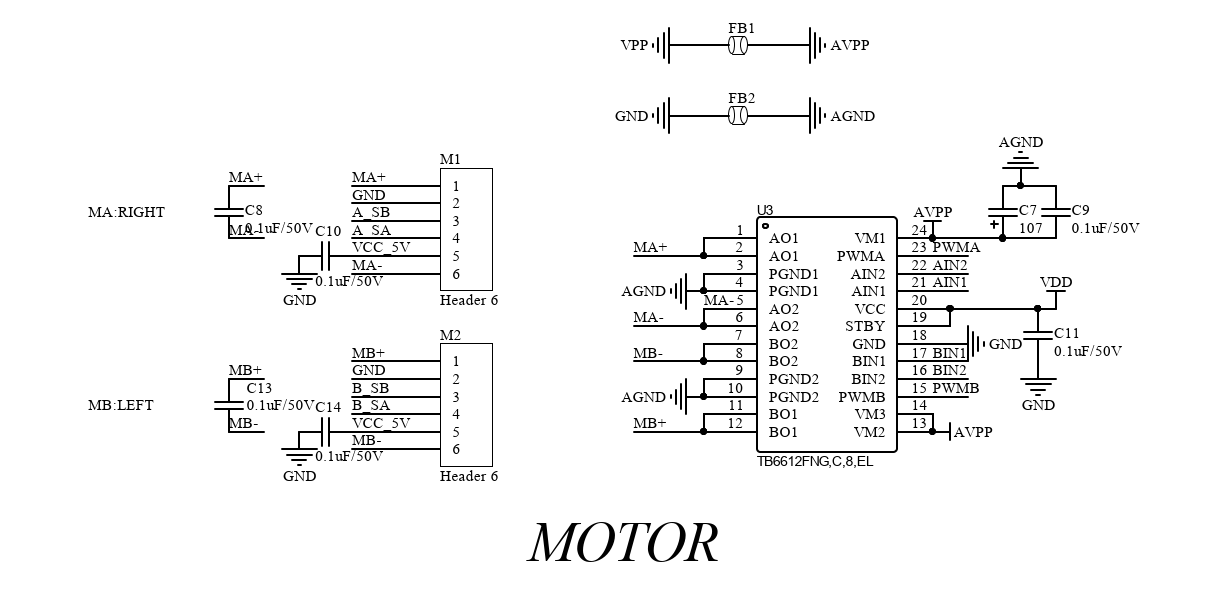
When
STBYpin is high, the two input signals,IN1andIN2, can be one of four modes such as clockwise (CW), counterclockwise (CCW), short brake, and stop mode.IN1 IN2 Mode 0 1 CCW 1 0 CW 1 1 Short brake 0 0 Stop The motor is integrated with a Hall effect sensor. The
VCC_ 5Vpin supplies power to the motor.Sensor
The MPU-6050 from InvenSense is the world’s first integrated 6-axis motion tracking device that combines a 3-axis gyroscope and a 3-axis accelerometer on the same silicon die. It has an onboard Digital Motion Processor (DMP) that is capable of processing complex 9-axis MotionFusion algorithms. When MPU-6050 is connected to an external magnetometer on its auxiliary I2C port, it delivers a complete 9-axis MotionFusion output to its primary I2C.
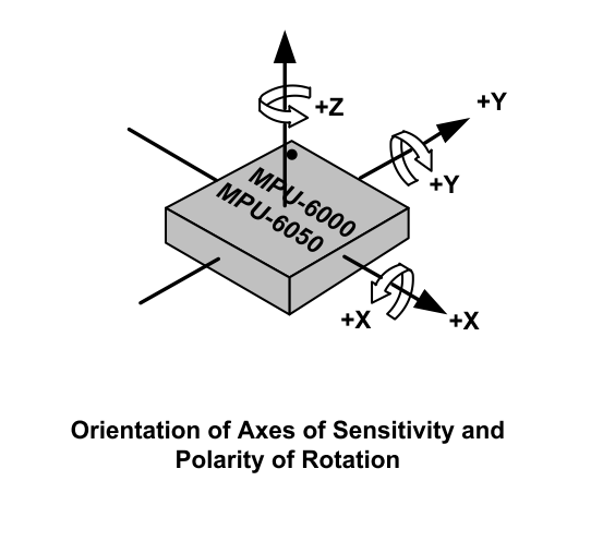
The MPU-6050 features three 16-bit analog-to-digital converters (ADCs) (0–65,535) for digitizing the gyroscope outputs and three 16-bit ADCs for digitizing the accelerometer outputs. For precision tracking of both fast and slow motions, the parts feature a user-programmable gyroscope range and accelerometer range.
The MPU-6050 consists of three independent vibratory MEMS rate gyroscopes, which detect rotation about the x-, y-, and z-axis. When the gyroscopes are rotated about any of the sense axes, the Coriolis Effect causes a vibration that is detected by a capacitive pickoff. The resulting signal is amplified, demodulated, and filtered to produce a voltage that is proportional to the angular rate. This voltage is digitized using individual on-chip 16-bit ADCs to sample each axis. The full-scale range of the gyroscope sensors can be digitally programmed to ±250, ±500, ±1,000, or ±2,000 degrees per second (dps). The ADC sample rate is programmable from 8,000 samples per second, down to 3.9 samples per second. User-selectable low-pass filters enable a wide range of cut-off frequencies.
The MPU-6050’s 3-axis accelerometer uses separate proof masses for each axis. Acceleration along a particular axis induces displacement on the corresponding proof mass, and capacitive sensors detect the displacement differentially. The MPU-6050’s architecture reduces the accelerometers’ susceptibility to fabrication variations as well as to thermal drift. When the device is placed on a flat surface, it will measure 0g on the x- and y-axis and +1g on the z-axis. The accelerometers’ scale factor is calibrated at the factory and is nominally independent of the supply voltage. Each sensor has a dedicated sigma-delta ADC for providing digital outputs. The full-scale range of the digital output can be adjusted to ±2g, ±4g, ±8g, or ±16g.
Camera
The pin configuration for the camera circuit is as follows.
FACTORY_ RSTis used to reset the camera for pairing with the mobile app. Press and hold theS3button for a specified period to trigger pairing mode.Connect
SPK+andSPK-to the internal beep of the camera.LED_REDandLED_ GREENare used to indicate the network status. The LED is steady on if the camera has been connected to the cloud. If the camera is being connected to the internet, the LED will blink in red and green alternately.Beep
The buzzer will sound a prompt to indicate normal operation and emit an audio alert to signal low battery.
Camera unit
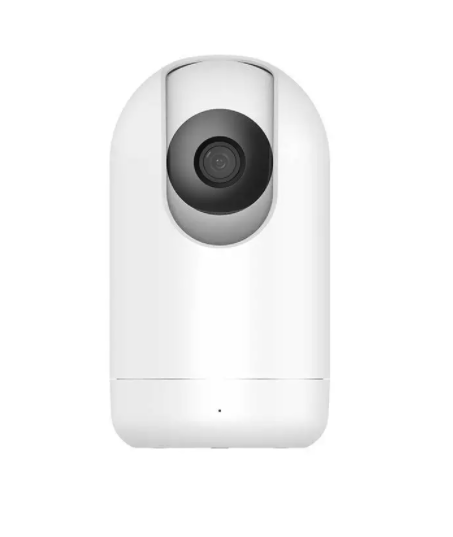
We choose Tuya’s SC012-WD2 smart camera. Its specification is as follows.
Processor High performance DSP processor Sensor 1/2.9 inch CMOS The highest resolution 1080P IR night vision distance Up to 7 meters IR night vision Built-in IR-CUT filter and automatic switching to night vision. Noise-reduction system 3D noise-reduction Focal length 4 mm Field of view (FoV) 94° Aperture F2.1 Video codec H.264/MJPEG Video bit rate High definition: 1.2 Mbps
Standard definition: 256 kbpsVideo frame rate High definition: 1080P 20 fps
Standard definition: VGA 20 fpsAudio input 1-channel microphone Audio output 1-channel speaker Restore defaults One-tap to restore defaults Motion detection Supported SD card capacity Store event recording and continuous recording on an SD card of up to 126 GB. Cloud storage Support storage of event recording and continuous recording. Privacy mode Supported Motion detection Supported Connectivity Wi-Fi IEEE 802.11 b/g/n, single-band (2.4 GHz) Power supply 5V/2A DC Operating temperature -10°C to 45°C Operating humidity ≤ 95% Power unit
We use a lithium polymer battery and gear motors to push wheels forward.
A lithium polymer battery is a rechargeable battery of lithium-ion technology using a polymer electrolyte. These batteries provide higher specific energy than other lithium battery types and are used in applications where weight is a critical feature, such as mobile devices.
An 11.1V lithium polymer battery with a capacity of 2200 mAh is recommended.
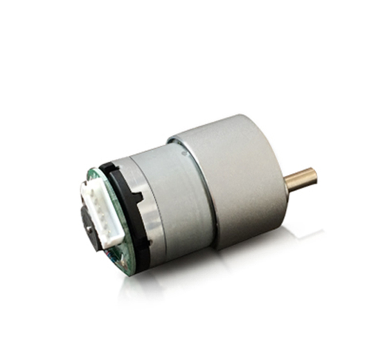
The geared motor can be defined as an extension of the DC motor. It has a gear assembly attached to the motor to increase the torque and reduce the speed.
The rated voltage of the geared motor must match that of the battery. Typically, the supply voltage of a 12V motor ranges from 11V to 16V, and a 12V battery is recommended.
We choose the MG513 DC 12V geared motor with a rated output current of 0.36A. Its reduction ratio is 1/30, and its no-load speed is 366 RPM. The motor can provide a torque of 1 kgf.cm and a maximum load of 3 kg. With 65 mm rubber wheels, the motor can reach a speed of 1 m/s.
Step 2: Device assembly
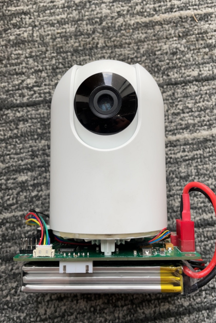
Prepare an SC012-WD2 Wi-Fi 1080P PTZ camera. If you select other camera models, contact technical support in case of any problems with your project.
Disassemble the base of the camera. Align the three tooling holes and attach the PCB to the smart camera. Mount other components and the battery.
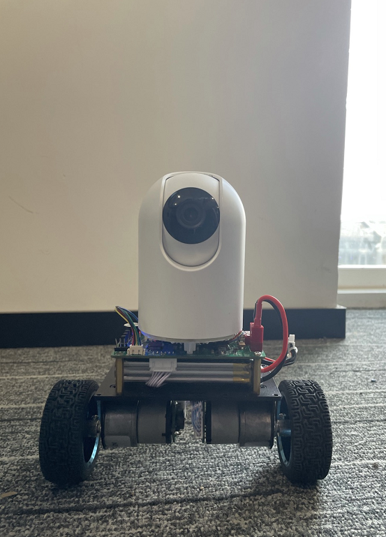
Attach the self-balancing robot car to the PCB part.
Congratulations, the assembly is done.
Step 3: Software development
Since we use Tuya’s SC012-WD2 smart camera, we do not need to write the camera-related embedded program and mobile app program. We only need to code for the self-balancing robot car.
Get reading from MPU-6050
The following code block shows how to get the balancing position from MPU-6050.
void Get_Angle(uint8_t way)
{
	float Accel_Y,Accel_Z,Gyro_X,Gyro_Z;
	Temperature=Read_Temperature();      //  Read the temperature data from MPU-6050's on-chip temperature sensor. You can take the reading as the approximate temperature of the motherboard.
	if(way==1)                           // The interrupt service is used to read data from the DMP. Make sure to respect the sequence.
	{
			Read_DMP();                      // Read the acceleration, angular velocity, and tilt angle.
			Angle_Balance=-Roll;             // Update the angle offset to balance the robot.
			Gyro_Balance=-gyro[0];            // Update the angular velocity to balance the robot.
			Gyro_Turn=gyro[2];               // Update the steering angular velocity.
			Acceleration_Z=accel[2];         // Update the z-axis of the accelerometer.
	}

 else
	{
		Gyro_X=(I2C_ReadOneByte(devAddr, MPU-6050_RA_GYRO_XOUT_H)<<8)+I2C_ReadOneByte(devAddr, MPU-6050_RA_GYRO_XOUT_L);    // Read the y-axis of the gyroscope.
		Gyro_Z=(I2C_ReadOneByte(devAddr, MPU-6050_RA_GYRO_ZOUT_H)<<8)+I2C_ReadOneByte(devAddr, MPU-6050_RA_GYRO_ZOUT_L);    // Read the z-axis of the gyroscope.
		Accel_Y=(I2C_ReadOneByte(devAddr, MPU-6050_RA_ACCEL_YOUT_H)<<8)+I2C_ReadOneByte(devAddr, MPU-6050_RA_ACCEL_YOUT_L); // Read the x-axis of the accelerometer.
		Accel_Z=(I2C_ReadOneByte(devAddr, MPU-6050_RA_ACCEL_ZOUT_H)<<8)+I2C_ReadOneByte(devAddr, MPU-6050_RA_ACCEL_ZOUT_L); //  Read the z-axis of the accelerometer.
		if(Gyro_X>32768)  Gyro_X-=65536;                       // You can cast the value to short type.
		if(Gyro_Z>32768)  Gyro_Z-=65536;                       // Data type casting.
		if(Accel_Y>32768) Accel_Y-=65536;                      // Data type casting.
		if(Accel_Z>32768) Accel_Z-=65536;                      // Data type casting.
		Gyro_Balance=Gyro_X+Gyro_X_OFFSET;                                  // Update the angular velocity to balance the robot.
		Accel_Angle=atan2(Accel_Y,Accel_Z)*180/PI;                 // Calculate the tilt angle.
		Gyro_X=Gyro_X/16.4;                                    // Convert the range of the gyroscope.
		if(way==2)		  	Kalman_Filter(Accel_Angle,Gyro_X);// Kalman filter
		else if(way==3)   First_order_Filter(Accel_Angle,Gyro_X);    // Complementary filter
		Angle_Balance=angle;                                     // Update the angle offset to balance the robot.
		Gyro_Turn=Gyro_Z+Gyro_Z_OFFSET;                                      // Update the steering angular velocity.
		Acceleration_Z=Accel_Z;                                // Update the z-axis of the accelerometer.
	 }
}
The
Accel_Angleis the reference angle we calculated.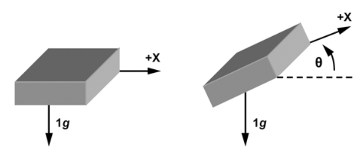
Alternatively, you can use this formula
Accel_Angle=arcsin(Accel_Y,Accel_G)*180/PI;to get the reference value.Accel_Gis calculated bysqrt(pow(Accel_X, 2) + pow(Accel_Y, 2) + pow(Accel_Z, 2));There is an error in the angles calculated by the above methods. When the accelerometer reads the angle, the acquired value error will increase when the outside is disturbed.

Therefore, filtering algorithms for angle error correction are required.
The Kalman filter and the first-order complementary filter are both available to get a more precise angle.
Kalman filter algorithm
The function is as follows:
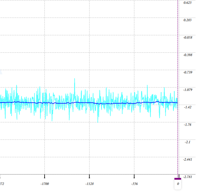
void Kalman_Filter(float Accel,float Gyro)

{
	angle+=(Gyro - Q_bias) * dt; // Prior estimate
	Pdot[0]=Q_angle - PP[0][1] - PP[1][0]; // The differential of error covariance of prior estimate

	 Pdot[1]=-PP[1][1];
	Pdot[2]=-PP[1][1];
	Pdot[3]=Q_gyro;
	PP[0][0] += Pdot[0] * dt;   // Integration of the differential of error covariance of prior estimate.
	PP[0][1] += Pdot[1] * dt;   // The error covariance of prior estimate.
	PP[1][0] += Pdot[2] * dt;
	PP[1][1] += Pdot[3] * dt;


	Angle_err = Accel - angle;	// Prior estimate


 PCt_0 = C_0 * PP[0][0];
	PCt_1 = C_0 * PP[1][0];


 E = R_angle + C_0 * PCt_0;


 K_0 = PCt_0 / E;
	K_1 = PCt_1 / E;


 t_0 = PCt_0;
	t_1 = C_0 * PP[0][1];

	PP[0][0] -= K_0 * t_0;		// The error covariance of posterior estimate.
	PP[0][1] -= K_0 * t_1;
	PP[1][0] -= K_1 * t_0;
	PP[1][1] -= K_1 * t_1;


	angle	+= K_0 * Angle_err;	  // Posterior estimate
	Q_bias	+= K_1 * Angle_err;	  // Posterior estimate
	angle_dot   = Gyro - Q_bias;	   // Output (the differential of posterior estimate) = Angle velocity
}
The following figure shows the comparison of the original tilt angle and the angle by Kalman filter.
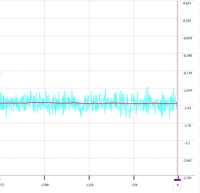
From the figure, you can see that the change in angle is largely different for the unfiltered angle.
First-order complementary filter
The function is as follows:
void First_order_Filter(float angle_m, float gyro_m)
{
   angle = K1 * angle_m+ (1-K1) * (angle + gyro_m * dt);
}
When you use this filter, call the following function.
First_order_Filter(Accel_Angle,Gyro_X);-
Accel_Angleis the original tilt angle we calculated. Refer to the Kalman filter method. -
Gyro_Xis the angular velocity of the x-axis, which can be read out from the sensor. Unit conversion is required.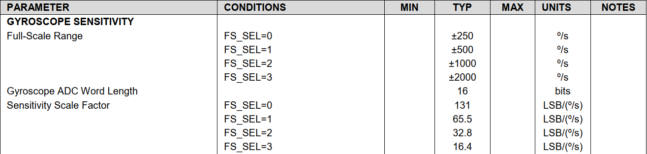
If you choose
FS_SEL=3(full-scale range of ±2000 º/s) for the MPU-6050, use the filter by following the description below.Gyro_X=Gyro_X/16.4;angle = K1 * angle_m+ (1-K1) * (angle + gyro_m * dt);-
angle_ mis the angle calculated based on the raw data from the sensor. -
gyro_ mis the angular velocity of a specific axis. -
dtis set to your desired sampling interval. If you want sample data every 5 ms, setdtto 0.05. If your MCU’s resource is sufficient, you can set a high frequency. -
gyro_m * dtindicates the rotation angle during the specifieddtinterval. -
K1depends on your requirement for sensitivity. The larger the K value is, the higher the sensitivity you get. If you want the data fluctuation to be little, set a smaller value. We set the K1 value to 0.02.
The following figure shows the comparison of the original tilt angle and the angle by the first-order complementary filter.
From the figure, you can see that the change in angle is largely different for the unfiltered angle.
Balance control
If we use the speed negative feedback in the uprightness control, the best velocity control cannot be made, and the balancing system might be compromised. Therefore, the velocity control should take precedence over the uprightness control, which means the result of velocity adjustment serves as the target for maintaining uprightness. The robot’s moving speed correlates with its tile angle. For example, to increase the forward speed, you need to increase the angle for leaning forward. Then, we have to rotate the wheels in the forward direction to maintain balance as a result of uprightness control, and the speed increases accordingly, and vice versa.
To achieve this logic, we design a cascade system and use the proportional–integral–derivative (PID) algorithm, which has the center position as a set-point and the level of disorientation as the output. The robot uses proportional derivative (PD) and proportional integral (PI) to control the vertical angle and the rotation speed respectively.
Vertical balance achieved by PD controller
int balance(float Angle,float Gyro)
{
   float Bias;
   int balancePID;
	 Bias=Angle-Angle_OFFSET;                       // Calculate the median value of the angle offset.
	 balancePID=Balance_Kp*Bias+Gyro*Balance_Kd;   // Calculate the PWM output required to keep the robot balanced. `kp` is the proportional coefficient and `kd` is the derivative coefficient.
	  return balancePID;
}
Rotation speed control achieved by PI controller
int velocity(int encoder_left,int encoder_right)
{
	static float Velocity,Encoder_Least,Encoder,Movement;
	static float Encoder_Integral,Target_Velocity;
	//=============Control the forward and backward movement=======================//
	Target_Velocity=40;
	if(Direction.Current==GO_STRAIGHT)   	Movement=-Target_Velocity/Flag_speed;	      // Forward movement flag 1
	else if(Direction.Current==GO_BACK)	Movement=Target_Velocity/Flag_speed;         // Backward movement flag 1
	else  Movement=0;
        //============= Rotation control by PI controller  =======================//
	 Encoder_Least =(encoder_left+encoder_right)-0;
	Encoder *= 0.8;		                                               // First-order low-pass filter
	Encoder += Encoder_Least*0.2;	                                      // First-order complementary filter
	Encoder_Integral +=Encoder;                                       // Integration for angular displacement calculation. The integration period is 10 ms.
	Encoder_Integral=Encoder_Integral-Movement;                       // Receive the command to make the robot car forward and backward.
	if(Encoder_Integral>8000)  	Encoder_Integral=8000;             // Integration limit.
	if(Encoder_Integral<-8000)	Encoder_Integral=-8000;              // Integration limit.
	Velocity=Encoder*Velocity_Kp+Encoder_Integral*Velocity_Ki;        // Speed control
	 if(Turn_Off(Angle_Balance,BAT_VOL)==1||Direction.Current==TURN_OFF)
	    Encoder_Integral=0;
	return Velocity;
}
Turning control
The following code block shows how to make the robot car turn left or right.
int turn(int encoder_left,int encoder_right,float gyro)// Turning control.
{
	static float Turn_Target,Turn,Encoder_temp,Turn_Convert=0.9,Turn_Count;
    float Turn_Amplitude=30/Flag_speed,Kp=32,Kd=0;
  	  	if(Direction.Current==TURN_LEFT||Direction.Current==TURN_RIGHT)
			{
					if(++Turn_Count==1)
					Encoder_temp=myabs(encoder_left+encoder_right);
					Turn_Convert=50/Encoder_temp;
					if(Turn_Convert<0.6)Turn_Convert=0.6;
					if(Turn_Convert>3)Turn_Convert=3;
			}
	  	  else
			{
					Turn_Convert=0.9;
					Turn_Count=0;
					Encoder_temp=0;
			}

		if(Direction.Current==TURN_LEFT){
					Turn_Target+=Turn_Convert;
		 }
			else if(Direction.Current==TURN_RIGHT){
					Turn_Target-=Turn_Convert;
		 }
			else Turn_Target=0;


    if(Turn_Target>Turn_Amplitude)  Turn_Target=Turn_Amplitude;    // Turning speed limit.
	    if(Turn_Target<-Turn_Amplitude) Turn_Target=-Turn_Amplitude;
			if(Direction.Current==GO_STRAIGHT||Direction.Current==GO_BACK||Direction.Current==KEEP_STOP)
		  	  Kd=-1 ;
			else
		  	  Kd=0;
  	//============= Turning control by PD controller=======================//
	Turn=-Turn_Target*Kp-gyro*Kd;                 // Use the z-axis of the gyroscope to control the turning of the robot car.
	    return Turn;
}
PWM control of motors
The above calculation provides the PWM output required to keep the robot balanced. Moto1 and Moto2 indicate the two motors we use.
	Balance_Pwm = balance(Angle_Balance,Gyro_Balance);// Balance control by PID controller
	Velocity_Pwm= velocity(Enconder_left,Enconder_right);// Rotation speed control by PID controller
	Turn_Pwm   = turn(Enconder_left,Enconder_right,Gyro_Turn);// Turning control by PID controller
	Moto1=Balance_Pwm+Velocity_Pwm-Turn_Pwm;// Calculate the final PWM output of the motor on the left wheel.
	Moto2=Balance_Pwm+Velocity_Pwm+Turn_Pwm;// Calculate the final PWM output of the motor on the right wheel.
	Limit_Pwm();                            // PWM limit
	Set_Pwm(Moto1,Moto2);                   //  Assign values to the PWM register.
After value assignment to the register, you can check the real movement state.
void Set_Pwm(int moto1,int moto2) { if(moto2>0) {AIN2_RESET;AIN1_SET;} else {AIN2_SET;AIN1_RESET;} TIM16_PWM_Set(myabs(moto2)); if(moto1>0) {BIN1_RESET;BIN2_SET;} else {BIN1_SET;BIN2_RESET;} TIM17_PWM_Set(myabs(moto1)); }-
Summary
The Tuya IoT Development Platform provides convenient IoT development tools and services, which are designed to make your IoT project much easier and efficient. Check it out and discover more awesome ideas.
Is this page helpful?
YesSuggestions


