Prototype a Smart Curtain Robot

Overview
A smart curtain robot can make your current curtains motorized and smart with easy installation. It offers the ultimate smart control with a mobile phone or voice assistant. With a shout or a tap, your curtains can give you privacy on-demand and open or close right at sunrise or sunset with preset automations. This little robot will not only make your curtain smart but will surely add some convenience to your day-to-day living.
Features
- Automatically open or close the curtain based on the preset threshold of light intensity.
- View the light intensity on the mobile app.
- Set the accurate opening/closing position on the mobile app.
- Manually pulling the curtain can trigger the motor to operate automatically.
Hardware
Materials
Tuya's Bluetooth LE module
Count:1Lithium battery
Count:13.7V 4000 mAh rechargeable lithium-polymer battery
Battery management chip
Count:1XT2052 from Natlinear
LDO regulator
Count:1TLV700F33 from 3PEAK
Ambient light sensor
Count:1OPT3004 from Texas Instruments
Linear accelerometer
Count:1LIS2DW12 from STMicroelectronics
Steps
Step 1: Hardware design
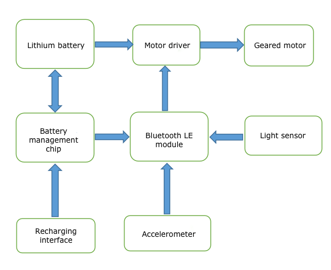
We use Tuya’s Bluetooth Low Energy module as the microcontroller and wireless connectivity unit. An ambient light sensor can measure the light intensity. An accelerometer can detect a manual pulling to trigger the motor to react and operate automatically.
Battery management unit
Power supply
Use a rechargeable 4000 mAh lithium battery pack (3.7V) to power the curtain motor without trailing wires or cords.
Battery management chip
Use a linear battery management chip XT2052 from Natlinear. This chip has the following features.
- The component includes an internal power transistor and does not need an external current sense resistor and blocking diode.
- Programmable charge current is up to 1A.
- Constant-current and constant-voltage operation with thermal regulation maximizes charge rate without risk of overheating.
- The chip automatically terminates the charge cycle when the charge current drops to 1/10th the programmed value after the final float voltage is reached.
- 40 μA current is supplied when the IC is shut down.
- Using an over-voltage protection circuit to prevent the device from damage when the supply voltage is higher than the OVP threshold of 6.8V.
Use an LDO regulator TLV700F33 from 3PEAK to provide 3.3V voltage. This LDO has the following features.
- Maximum output current: 300 mA
- Low dropout voltage: 200 mV at 300 mA
- Low quiescent current: 50 μA
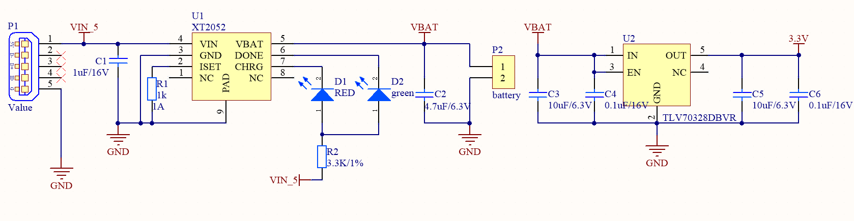
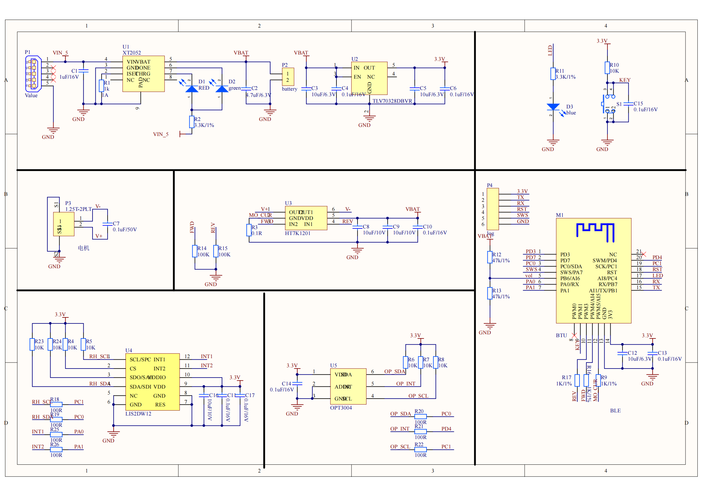
Circuit diagram
-
The maximum charge current is 1A.
-
The two LEDs indicate the progress of charging. Steady red light means that the battery is charging. Steady green light means that the battery is fully charged.
-
VBat is the voltage of the battery and is used to power the motor. The LDO steps down the power source to 3.3V DC to supply the Bluetooth LE module and sensor.
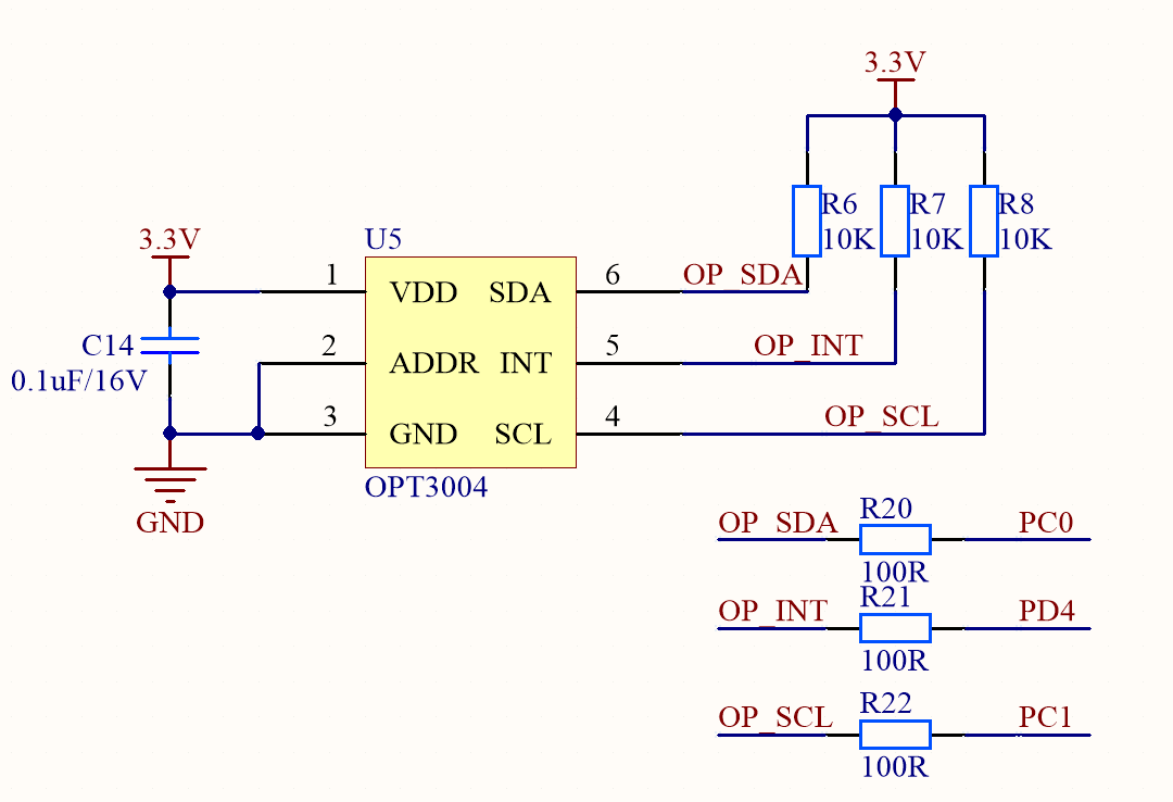
Ambient light sensor
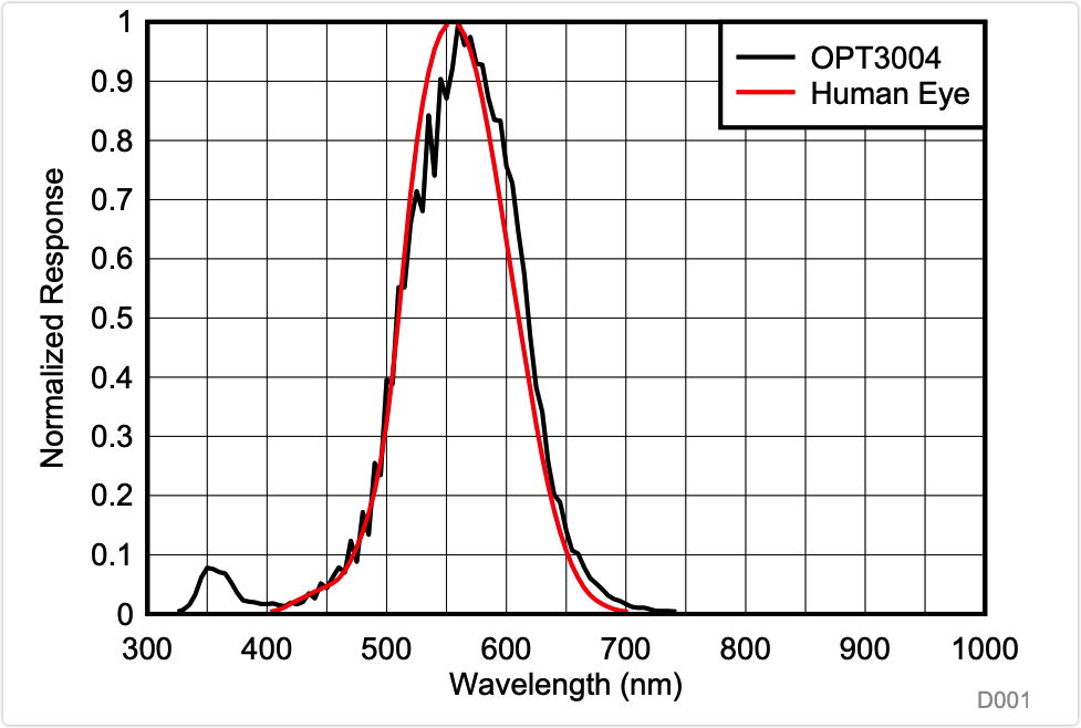
The photoresistor, photodiode, and ambient light sensor are the common components used to sense light intensity. Both the photoresistor and photodiode are fundamentally analog components. The output analog signals must first be converted into a digital value before a microcontroller can use it. The ambient light sensor OPT3004 can directly output the measured lux value. The ambient light sensor OPT3004 trumps the other two components in the following aspects.
- Low operating current: 1.8 µA (Typical)
- Measurements: 0.01 lux to 83k lux
- Direct output of lux value without conversion.
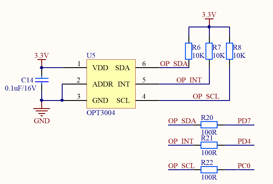
Circuit diagram
Linear accelerometer
To detect the manual pulling action, we use a three-axis linear accelerometer LIS2DW12 from STMicroelectronics to achieve portrait/landscape orientation detections. It uses less than 1 µA in low-power mode.
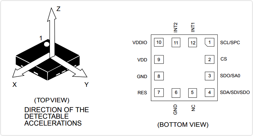
Circuit diagram
I2C is chosen as the digital output interface. It can use the
CSpin to select I2C or SPI mode.Since the accelerometer LIS2DW12 and the ambient light sensor OPT3004 use a different address, these two sensors can share one I2C bus interface.
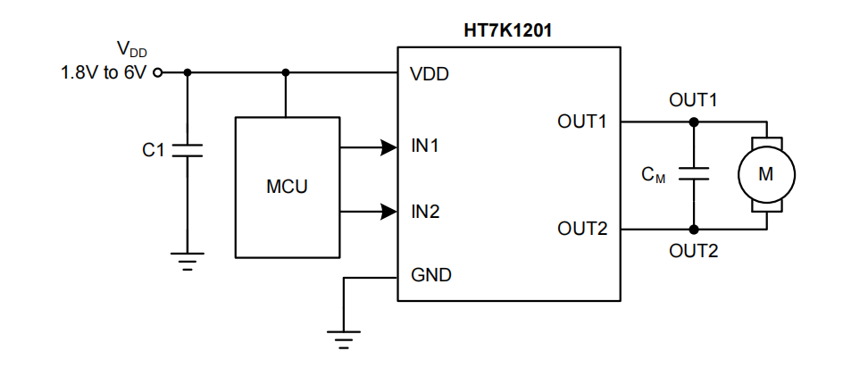
Motor driver
The robot is driven by the friction between the pulleys and rail. This requires high torque output at lower shaft speeds to push up the curtain and the robot. Therefore, we choose a geared motor.
A geared motor is a combination of a gear system or gearbox and an electric motor. Gears transform shaft speed and torque at specific ratios, with minimum efficiency losses.We use a 1-channel H-bridge driver HT7K1201 from Holtek Semiconductor. This driver has the following features.
- Wide VDD input voltage range of 1.8V to 6.0V.
- Maximum 1.3A motor peak current.
- Sleep current of less than 0.1 μA.
- Low MOSFET on-resistance of 0.5Ω (HS+LS).
- Four operation modes: forward, reverse, brake, and standby.
- VDD under-voltage lock-out (1.5V). Over-current protection (1.3A).
- Output short circuit protection (1.9A). Thermal shutdown protection.
Microcontroller unit
Tuya’s Bluetooth LE module works as the microcontroller. We develop with this module to achieve Bluetooth connectivity, motor control, and data collection.
In the circuit, an LED and a reset button are added to indicate network status and reset the module.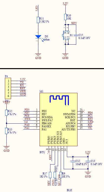
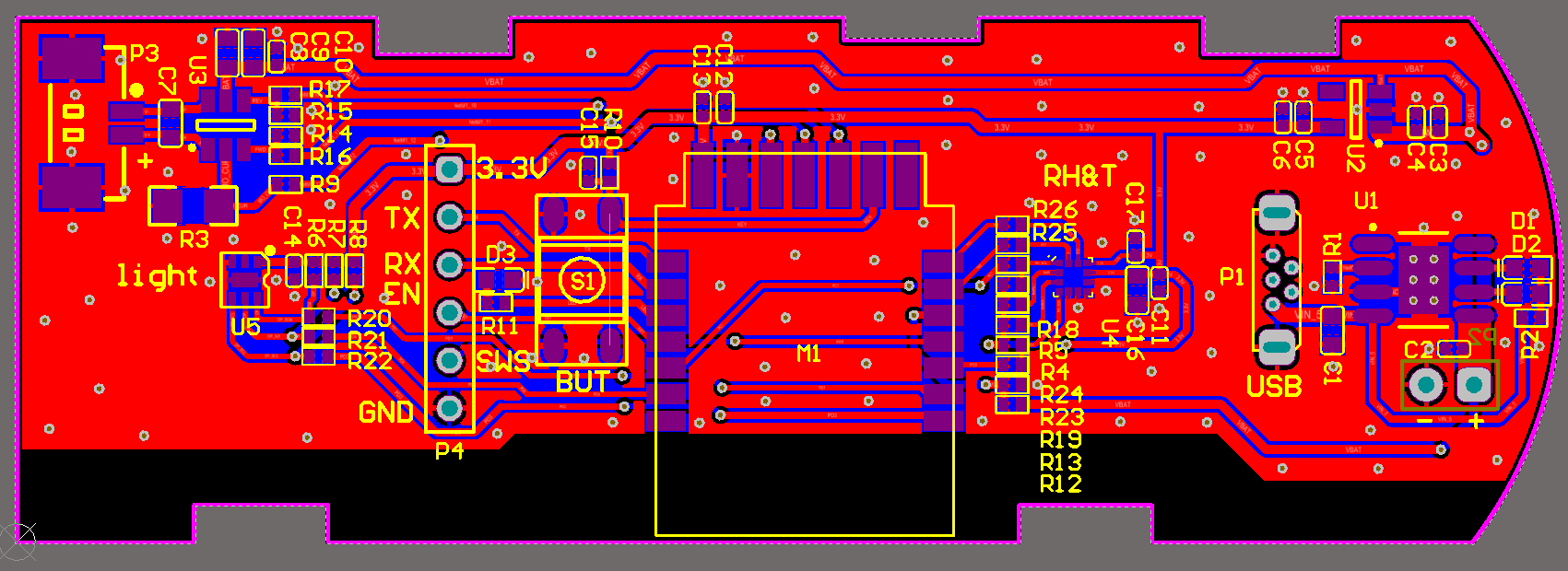
Schematic diagram and PCB
Step 2: Creates a product
-
Log in to the Tuya IoT Platform.
-
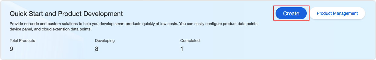
Click Create.
-
On the Standard Category tab, select Small Home Appliances > Motor > Curtain.

-
On the Custom Solution tab, select Curtain.
-
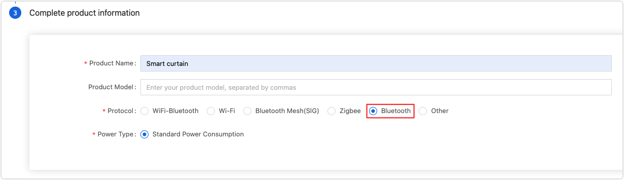
Complete the product details and select Bluetooth as the protocol.
-
Click Create.
-
In the second step of the Device Panel tab, select the desired panel.
-
In the third step of Hardware Development, select Tuya Standard Module SDK.
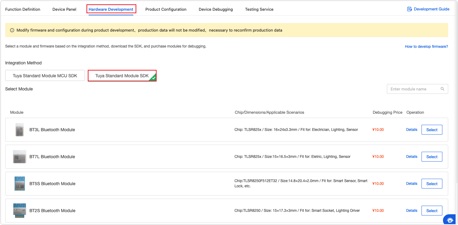
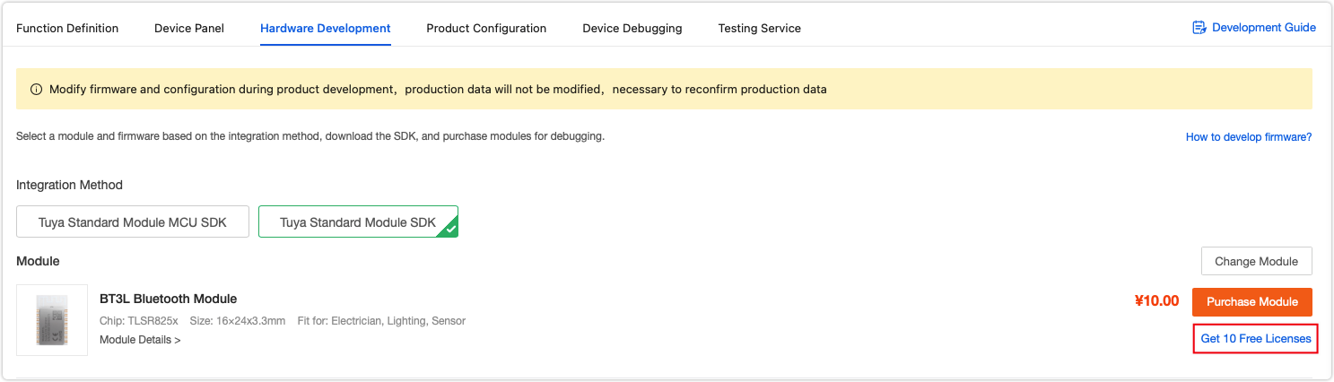
-
Click Get 10 Free Licenses on the right side of the screen. You will get the UUID, key, and MAC address used in coding.
-
Step 3: Get the SDK and set up IDE
-
GitHub repo
Clone this repo tuya_ble_sdk_Demo_Project_tlsr8253 to your local computer and check out theREADME.md. -
Set up IDE
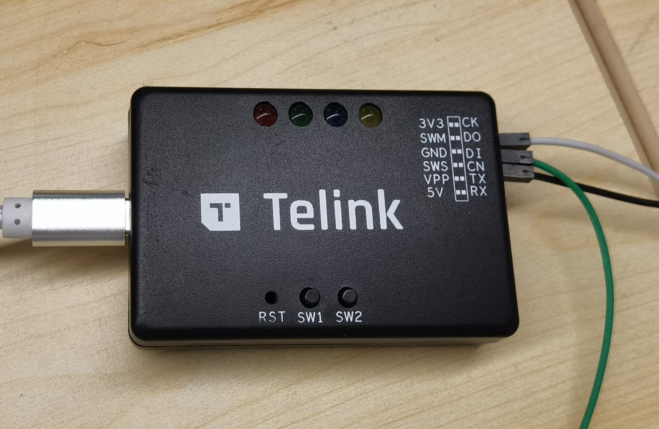
The chip on the module is TLSR825x so we use Telink IDE for development. Go IDE for TLSR8 Chips and download the IDE and check out the project import guide.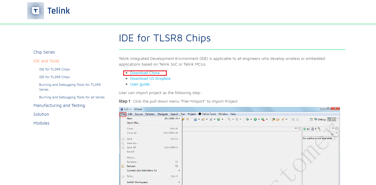
After you have the IDE installed, import your project.
-
Develop with project
- Edit the product ID.
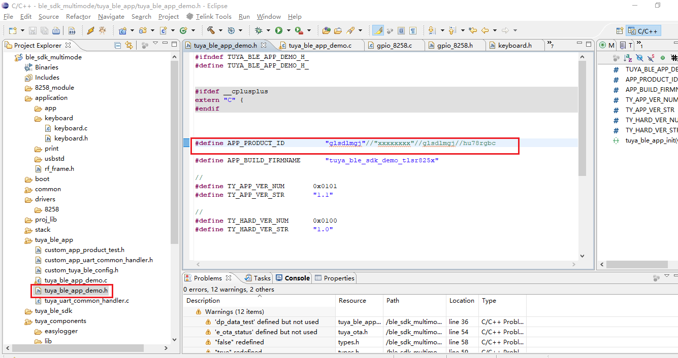
- Edit the
auth_key,device_id, andmac.
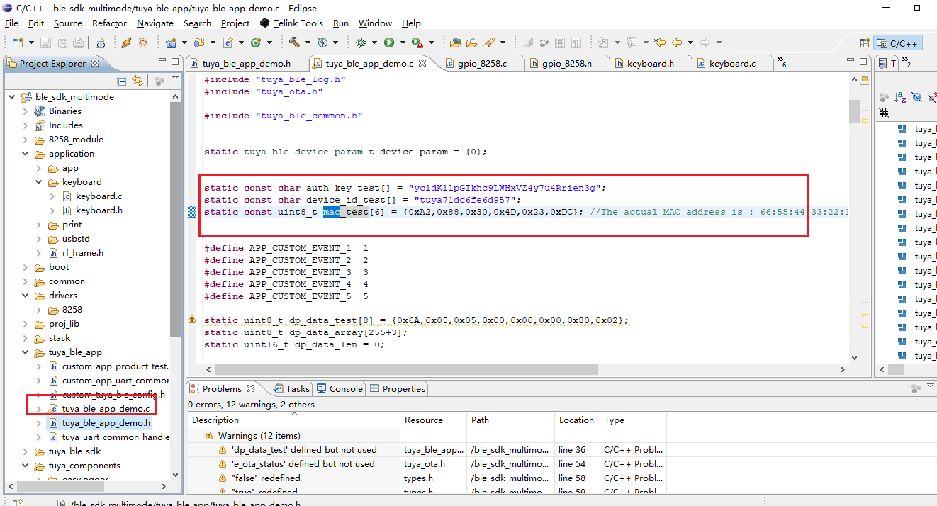
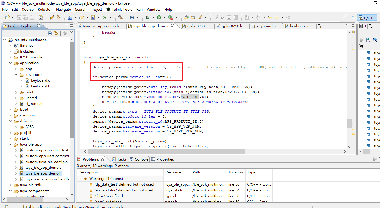
- Compile code.
-
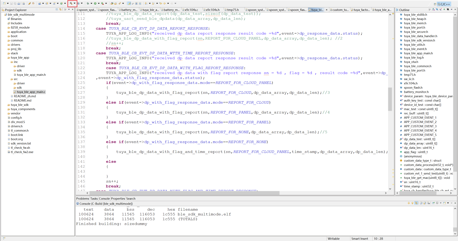
Flashing tool (Download)
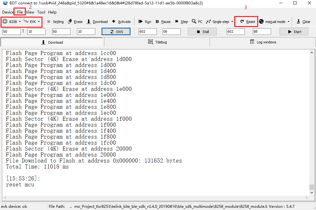
-
Select
8258as the chip type andEVKas the download mode. Click File and select thebinfile to be downloaded into the board, which is located intuya_ble_sdk_Demo_Project_tlsr8253\telink_kite_ble_sdk_v3.4.0_20190816\ble_sdk_multimode\8258_module\8258_module.bin. -
After downloading, click Reset to run it.
-
We use Telink’s writer. Connect the SWM header on the board to the SWM header on the writer.
Note:
- When the GPIO reads high, it returns a value greater than 1, which might be 1, 2, or 128.
- The pin of log printing defaults to
TL_C2, with a baud rate of 230400. Since we do not have enough I/Os, we change the pin of log printing toTL_D3. You can compile code after the editing. The configuration file is located intuya_ble_sdk_Demo_Project_tlsr8253\telink_kite_ble_sdk_v3.4.0_20190816\ble_sdk_multimode\vendor\8258_module\app_config.h.
In line 47:
#define DEBUG_INFO_TX_PIN GPIO_PC2Changed to:
#define DEBUG_INFO_TX_PIN GPIO_PD3 -
-
Step 4: Software design
Required features
Feature Description Note Normal control Three control modes: open, close, and stop. The motor must stop in any situation once the stopbutton is pressed.Percentage control Open/close the curtain with percentage control based on the length of the curtain. Auto measurement of curtain length Measure how long it takes for the robot to completely close the curtain from 0% to 100%. Motor rotation direction Change the rotation direction of the motor. The rotation can be forward or reverse. Motion detection When the robot senses that you are dragging the curtain, it will assist you to complete the whole process by supporting force. The name of this feature displayed on the mobile app is Auto Power. Light intensity display Feed the measured light intensity to the mobile app for display. The measurement unit is in lux. Light-based curtain automation Set the max and min lux values. When the light intensity reaches the preset threshold, the curtain will be automatically opened or closed. Divide your desired max/min value by 10. For example, if you set the value to 10, it means when the light intensity is below 100 lux, the curtain will be closed. Note: If you do not intend to use the auto-closing feature, opening the curtain twice will disable this feature.
Battery level display Display the current battery level on the mobile app. Implementation: normal control and percentage control
To implement both the control methods, we must get the length of the curtain. Since the rotational speed of the motor is constant, we can count how long it takes for the motor to completely close the curtain from 0% to 100% and then calculate the length of the curtain. To pull the robot to the set position, calculate the travel time based on the starting and stopping position of the motor.
After receiving the command of the percentage control from the mobile app, the application calls
void curtain_percent_control(unsigned char current_position, unsigned char target_position)to pull the robot to the corresponding direction and save the required travel time to the global variable that the task termination function will use.void curtain_percent_control_stop_task(void)will run until the motor travel stops. Then, this function will save the current position of the motor to the flash memory and report the motor status to the cloud accordingly.Sample code for percentage control
void curtain_percent_control(unsigned char current_position, unsigned char target_position)
{
	unsigned long total_time;

	if ((current_position == target_position) || \
		(current_position < 0) || (current_position > 100) || \
		(target_position < 0) || (target_position > 100)) {
		TUYA_APP_LOG_ERROR("input error");
		*curtain_robot.dp_percent_state.dp_data = current_position;
		return;
	}

	if (curtain_robot.motor_run_mode == RUN_MODE_IDLE) {
		curtain_robot.motor_run_mode = RUN_MODE_PERCENT_CONTROL;
	} else {
		TUYA_APP_LOG_ERROR("motor_run_mode != RUN_MODE_IDLE");
		*curtain_robot.dp_percent_state.dp_data = current_position;
		return;
	}

	total_time = curtain_robot.dp_time_total.dp_data[0];
	total_time = (total_time << 8) | curtain_robot.dp_time_total.dp_data[1];

	if (total_time == 0) {
		*curtain_robot.dp_percent_state.dp_data = current_position;
		return;
	}

	if (current_position < target_position) {
		curtain_robot.run_end_time = ((target_position - current_position) * (total_time * 10)); //*10=*1000/100,ms->us
		curtain_robot.run_start_time = clock_time();
		curtain_close();
	} else {
		curtain_robot.run_end_time = (current_position - target_position) * (total_time * 10);
		curtain_robot.run_start_time = clock_time();
		curtain_open();
	}

	/* percent control state target position */
	percent_target_value = target_position;

	*curtain_robot.dp_percent_control.dp_data = target_position;
	/* percent control */
	dp_update(curtain_robot.dp_percent_control.dp_id,	\
			curtain_robot.dp_percent_control.dp_type,	\
			curtain_robot.dp_percent_control.dp_data,	\
			curtain_robot.dp_percent_control.dp_data_len);
}

void curtain_percent_control_stop_task(void)
{
	if (((curtain_robot.motor_run_mode == RUN_MODE_PERCENT_CONTROL)) && \
		(clock_time_exceed(curtain_robot.run_start_time, curtain_robot.run_end_time))) {
		curtain_pause();
		curtain_robot.motor_run_mode = RUN_MODE_IDLE;

		save_device_data();

		/* percent state */
		*curtain_robot.dp_percent_state.dp_data = percent_target_value;
		dp_update(curtain_robot.dp_percent_state.dp_id,	\
				curtain_robot.dp_percent_state.dp_type,	\
				curtain_robot.dp_percent_state.dp_data,	\
				curtain_robot.dp_percent_state.dp_data_len);

	}
}
Implementation: auto measurement of curtain length
To get the length of the curtain automatically, we need to measure the length of the curtain track. The key step is to determine whether the robot arrives at the travel destination. All the motor-dependent features require the travel time of the motor.
We provide two solutions here.
-
Given that the voltage of the
MO_CURpin is higher in motor stalling than that in normal operation, we can determine whether the robot arrives at the travel destination by the voltage change due to stalling.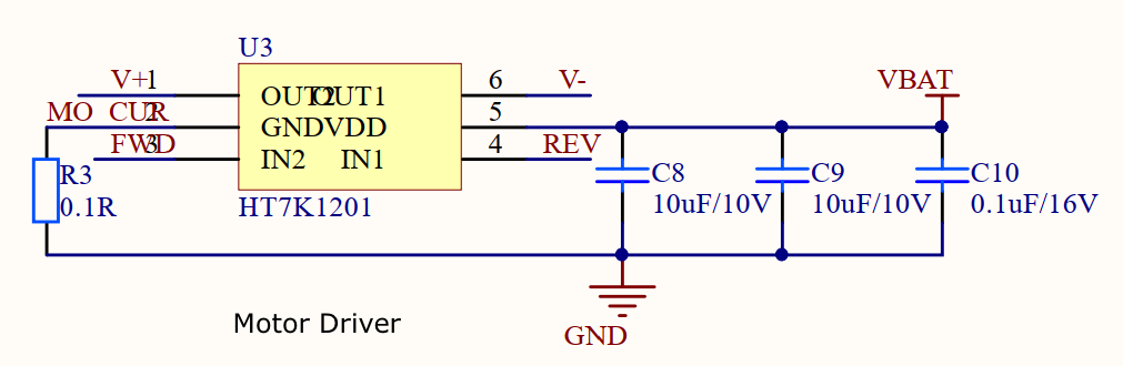
-
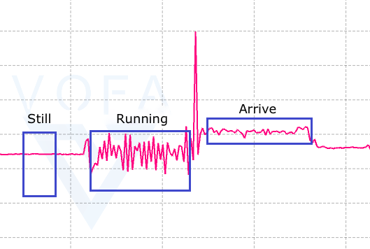
Alternatively, we can use the accelerometer LIS2DW12 to determine the completion of motor travel. According to the placement of LIS2DW12, the acceleration values measured from the X-axis can be a determinant of the motor status. The following figure shows the data measured from the X-axis when the robot runs. The signal is flat when the robot is still and starts fluctuating after the robot moves. The signal surges on a collision. When the robot arrives at the destination, the signal is higher than that in the stationary state, with smaller fluctuation.
The first solution provides an at-a-glance way to determine the completion of motor travel. The accelerometer can help you check the current motor status. Choose a solution as needed.
Implementation: motion detection
The values measured when you starting pulling the drapes correlates with the curtain moving direction. We can use the values at the starting point to determine the pulling direction.
Sample code
short x_data_buf[100] = {0};
unsigned int clean_x_buf_count = 0;
unsigned char x_data_index = 0;

void auto_power_task(void)
{
	short x_axis_data = 0;
	unsigned char i = 0;
	unsigned char open_count = 0, close_count = 0;

	if (*(curtain_robot.dp_auto_power.dp_data) == TRUE) {
		if (clock_time_exceed(curtain_robot.get_lis2dw12_data_time, 10 * 1000)) {
			curtain_robot.get_lis2dw12_data_time = clock_time();

			if (curtain_robot.motor_run_mode != RUN_MODE_IDLE) {
				return;
			}

			x_axis_data = get_lis2dw12_x_value();

			if (x_axis_data > 100 || x_axis_data < -100) {
				x_data_buf[x_data_index] = x_axis_data;
				x_data_index++;

				clean_x_buf_count = 0;
			} else {
				clean_x_buf_count++;
			}

			if ((clean_x_buf_count > 20) && (x_data_index >= 20)) { //At this point it has levelled off
				for (i=0; i < 7; i++) {
					if (x_data_buf[i] >= 0) {
						open_count++;
					} else {
						close_count++;
					}
				}

				if (*curtain_robot.dp_percent_state.dp_data == 0) {
					curtain_robot.auto_power_state = AUTO_POWER_CLOSE;
				} else if (*curtain_robot.dp_percent_state.dp_data == 100) {
					curtain_robot.auto_power_state = AUTO_POWER_OPEN;
				} else if (open_count < close_count) {
					curtain_robot.auto_power_state = AUTO_POWER_CLOSE;
				} else {
					curtain_robot.auto_power_state = AUTO_POWER_OPEN;
				}

				//clean flag
				clean_x_buf_count= 0;
				x_data_index=0;
			}

			if (curtain_robot.auto_power_state != AUTO_POWER_IDLE && clean_x_buf_count>= 100) {
				if (curtain_robot.auto_power_state == AUTO_POWER_OPEN) {
					curtain_percent_control(*curtain_robot.dp_percent_state.dp_data, 0);
				} else if (curtain_robot.auto_power_state == AUTO_POWER_CLOSE) {
					curtain_percent_control(*curtain_robot.dp_percent_state.dp_data, 100);
				}
				curtain_robot.auto_power_state=AUTO_POWER_IDLE;
				clean_x_buf_count = 0;
			}

			if (clean_x_buf_count > 500) {
				clean_x_buf_count = 0;
				x_data_index=0;
			}
		}
	}
}
Implementation: light intensity display
The ambient light sensor OPT3004 can communicate with the module through the I2C protocol. We can read the result register to get the current lux value.
Sample code
#define I2C_CLK_SPEED 200000

short lsb_size_tab[] = {1, 2, 4, 8, 16, 32, 64, 128, 256, 512, 1024, 2048};

unsigned char opt3004_init(void)
{
    unsigned char device_id_data_buf[2] = {0};
    unsigned char manufacturer_id_data_buf[2] = {0};

    unsigned char write_data[2] = {0xcc, 0x10};

    unsigned long delay_time = 0;

    i2c_gpio_set(I2C_GPIO_GROUP_C0C1);

    i2c_master_init(OPT3004_I2C_ADDR_W, (unsigned char)(CLOCK_SYS_CLOCK_HZ / (4 * I2C_CLK_SPEED)));
    i2c_write_series(OPT3004_CONFIG_REGISTER_ADDR, 1, write_data, 2);

    i2c_master_init(OPT3004_I2C_ADDR_R, (unsigned char)(CLOCK_SYS_CLOCK_HZ / (4 * I2C_CLK_SPEED)));

    i2c_read_series(OPT3004_DEVICE_ID_REGISTER_ADDR, 1, device_id_data_buf, 2);
    delay_time = clock_time();
    while (!clock_time_exceed(delay_time, 100)); //100us delay
    i2c_read_series(OPT3004_MANUFACTURER_ID_REGISTER_ADDR, 1, manufacturer_id_data_buf, 2);
    if ((((device_id_data_buf[0]<<8) + device_id_data_buf[1]) != DEVICE_ID) || \
		(((manufacturer_id_data_buf[0]<<8) + manufacturer_id_data_buf[1]) != MANUFACTURER_ID)) {
        return 0;
    }

    return 1;
}

short get_opt3004_value(void)
{
	short ret_value = -1;
	int result_value = 0;
	short result_data_e = 0, result_data_r = 0;
	unsigned char opt3004_cfg_data[2] = {0};
	unsigned char opt3004_result_data[2] = {0};

	i2c_master_init(OPT3004_I2C_ADDR_R, (unsigned char)(CLOCK_SYS_CLOCK_HZ / (4 * I2C_CLK_SPEED)));

	i2c_read_series(OPT3004_CONFIG_REGISTER_ADDR, 1, opt3004_cfg_data, 2);
	if (opt3004_cfg_data[1]&0x80) {
		i2c_read_series(OPT3004_RESULT_REGISTER_ADDR, 1, opt3004_result_data, 2);
		result_value = (opt3004_result_data[0]<<8) + opt3004_result_data[1];

		result_data_e = ((result_value & 0xF000) >> 12);
		result_data_r = (result_value & 0x0FFF);
		ret_value = lsb_size_tab[result_data_e] * result_data_r / 100;
		TUYA_APP_LOG_DEBUG("ret_value:%d", ret_value);
	}
	return ret_value;
}
Control panel
This all-in-one panel provides the user interface for controlling the robot on a mobile phone.

-
Summary
So far, a basic smart curtain robot prototype is made. We provide some improvements that you can make to your project.
Hardware
-
Choosing a removable lithium battery can save you the battery management chip and provide a flexible charging experience.
-
If you do not require high accuracy of lux value, the photodiode and photoresistor are the alternatives.
-
To determine the completion of motor travel, you can try the accelerometer LIS2DW12.
Software
-
We detect the collision by the change of motor voltage. You can try the accelerometer-based solution.
-
In this project, we only implement auto closing as per the light intensity. You can implement the setting of a max/min lux value to achieve auto opening/closing.
-
Add a feature of obstruction detection. If there is heavy obstruction while operating, the curtain will stop. This feature can protect the motor and lengthen its service life.
Is this page helpful?
YesSuggestionsNext Step


