Integrate Tuya Open Source Smart Environmental Monitoring Solution for Multi-Hazard Detection
Overview
With rapid economic growth, income increases, and enhancement of safety awareness, people pay more and more attention to the quality of life. However, according to the survey, the current air detectors on the market either have a single function, measurement is not accurate, or they cannot be intelligently linked with other devices such as air purifiers and air conditioners, or cannot be viewed on a mobile app, or the price is unaffordable.
What can we do?
Tuya Smart has a solution ready for you!
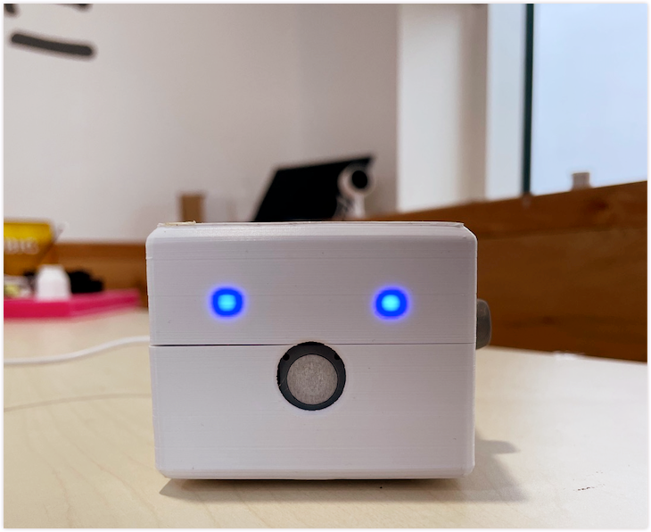
In order to solve these challenges, we have designed a new smart hardware solution for air management, namely, Environment Monitor.
This powerful solution can detect the concentrations of formaldehyde and PM2.5 in the environment, and display these two values in real-time on the Tuya Smart app. It can also monitor the concentrations of smoke, gas, and flame in real-time. When the concentration of the detected object exceeds a threshold, an alarm will be triggered and other smart devices will be linked to protect the safety of users and their property.
Materials
WB3S network module
Count:1WB3S is a low-power Wi-Fi and Bluetooth Low Energy combo module developed by Tuya Smart. It consists of a highly integrated radio-frequency identification (RFID) chip BK7231T and a few peripheral components, with a built-in Wi-Fi network protocol stack and various library functions.
4-channel analog multiplexer/demultiplexer chip RS2255
Count:1As a digitally controlled analog switch, its on-resistance is only 24 ohms, and its leakage current is only 1 nA.
ZE08-CH2O formaldehyde sensor module
Count:1The module uses electrochemical principles to detect CH2O in the air, with good selectivity and stability.
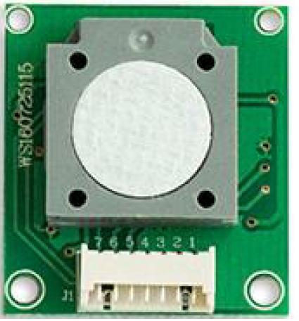
ZPH02 particles sensor
Count:1Integrating infrared PM2.5 detection principle and mature VOC detection technology, it can detect PM2.5 and VOC in the environment.
MQ-2 smoke sensor
Count:1It is used in gas leakage detectors in homes and factories to measure liquefied petroleum gas, benzene, alkane, alcohol, hydrogen, smoke, and more.
Flame detection IR receiver diode
Count:1Detect fire sources or heat sources with a wavelength in the range of 700 to 1000 nm.
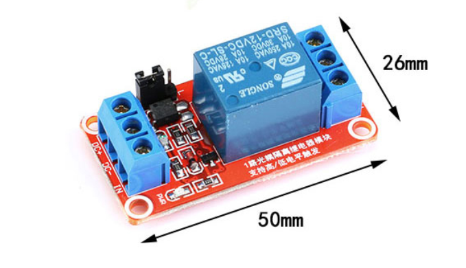
(Optional) 1-channel relay module
Count:1When an anomaly occurs, the 220V power grid is automatically disconnected to reduce losses.
Steps
Step 1: Select hardware solutions
1. Master control solution
The WB3S network module is used as the master control unit. WB3S is a low-power Wi-Fi and luetooth Low Energy combo module developed by Tuya Smart. It consists of a highly integrated radio-frequency identification (RFID) chip BK7231T and a few peripheral components, with a built-in Wi-Fi network protocol stack and various library functions.
To extend the insufficient ADC resources of the module, we need to modify the module by adding a 4-channel analog multiplexer/demultiplexer chip RS2255 to the circuit. As a digitally controlled analog switch, its on-resistance is only 24 ohms, and its leakage current is only 1 nA.
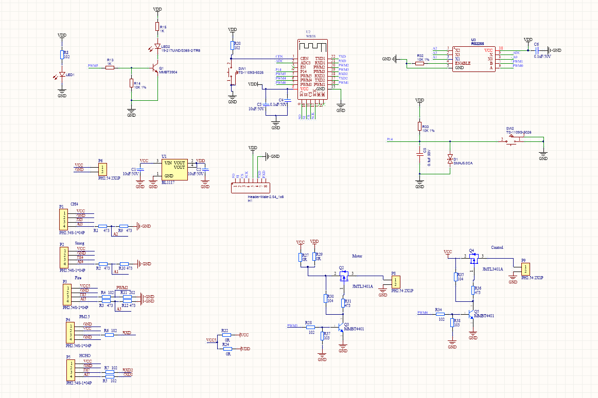
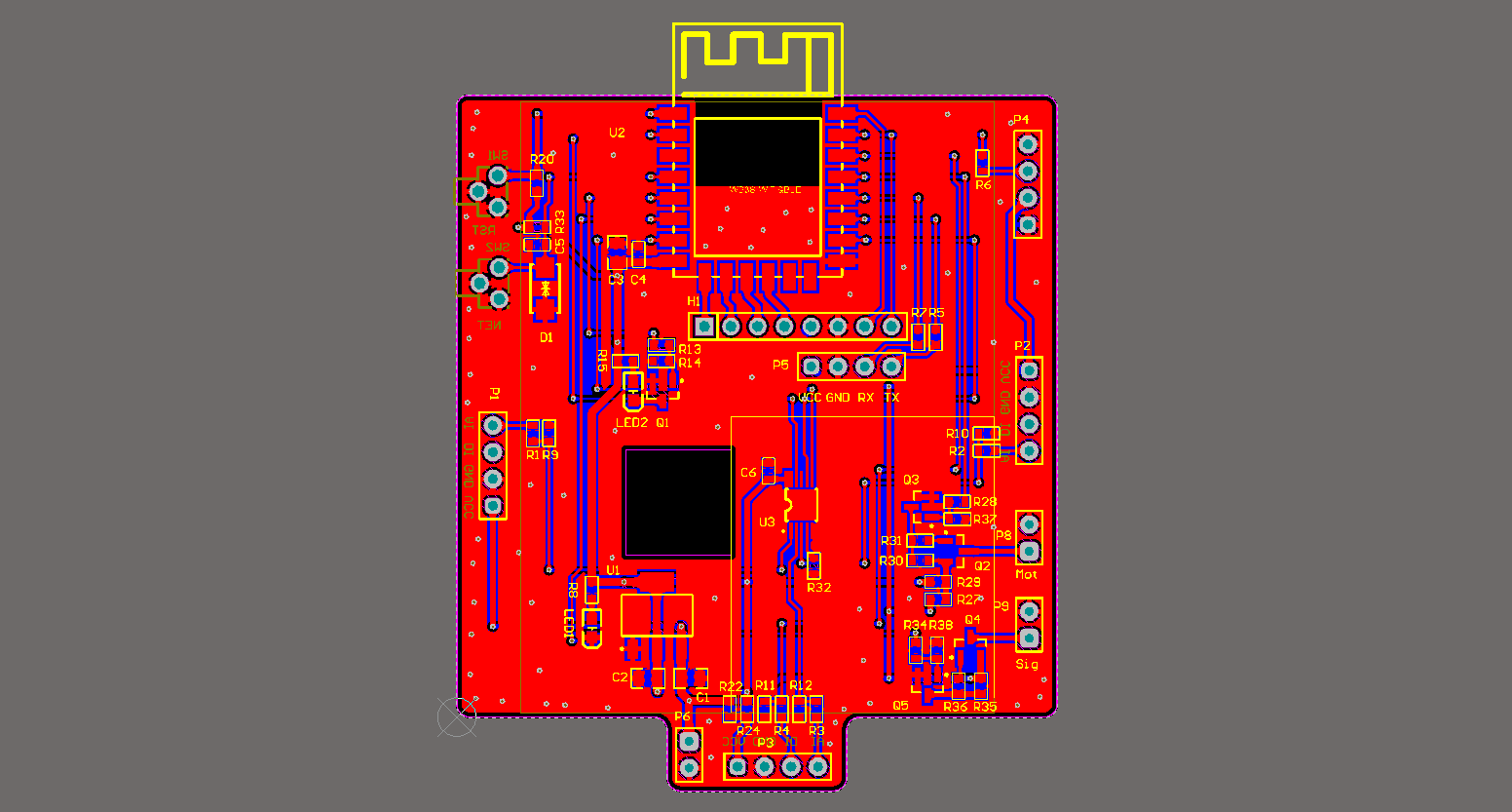
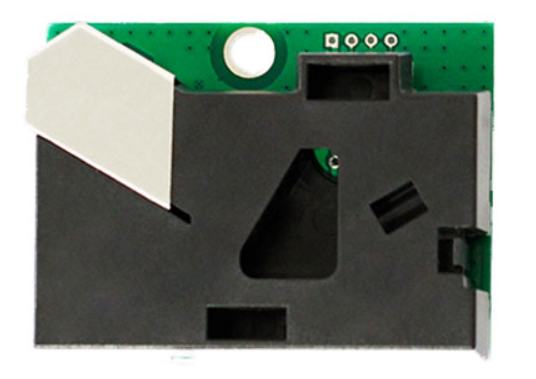
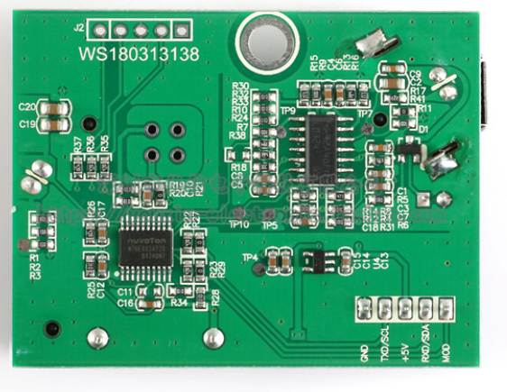
This solution uses many sensors. In order to reduce the wiring and make the layout more concise and neat, you can break out pins on the master board to connect to sensors. The levels at the communication interface between each module and the master control board do not match, and the power supply voltage varies by the modules. To troubleshoot the issue, we have designed the circuit and PCB as follows.
2. Formaldehyde sensor solution
This solution uses a general-purpose, miniaturized ZE08-CH2O electrochemical formaldehyde module.
The module uses electrochemical principles to detect CH2O in the air, with good selectivity and stability. A built-in temperature sensor provides temperature compensation. Both digital output and analog voltage output are available.
-
Electrical specifications are as follows:
Product model ZE08-CH2O Target gas Formaldehyde Interferent Alcohol, carbon monoxide, and other gases Output data DAC (0.4–2V voltage signal, corresponding concentration: 0 to full scale) UART output (3V TTL level) Operating voltage 3.7–5.5V Preheating time ≤ 3 minutes Response time ≤ 60 seconds Recovery time ≤ 60 seconds Scale 0–5 ppm Resolution ≤ 0.01 ppm Operating temperature -20–50°C Operating humidity 15%–90% RH (non-condensing) Storage temperature 0–25°C Service life 5 years (18–25°C in the air) -
The definitions of pins are as follows:
Pin name Description Pin1 Reserved Pin2 DAC (0.4–2V voltage signal, corresponding concentration: 0 to full scale) Pin3 GND Pin4 VIN (3.7–5.5V voltage input) Pin5 UART (RXD) 0–3.3V data input Pin6 UART (TXD) 0–3.3V data output Pin7 Reserved -
The serial communication protocol is as follows:
Byte0 Byte1 Byte2 Byte3 Byte4 Byte5 Byte6 Byte7 Byte8 Start bit Gas name Unit Number of decimals Gas concentration Gas concentration Full scale Full scale Check value (CH2O) (ppb) None High bit Low bit High bit Low bit 0xFF 0x17 0x04 0x00 0x00 0x25 0x13 0x88 0x25
Note:
Gas concentration (PPB) = high bit of gas concentration × 256 + low bit of gas concentration. When converted to ppm:ppm = PPB/1000,1 ppm × 1.25 = 1.25 mg/m3.
Among them, Byte8 check value = (reversed (Byte1+Byte2+…+Byte7))+1.
3. PM2.5 sensor solution
ZPH02 particles sensor is used to detect PM2.5. Integrating infrared PM2.5 detection principle and mature VOC detection technology, it can detect PM2.5 and VOC in the environment.
This sensor adopts the principle of particle counting to sensitively detect dust particles with a diameter of more than 1 μm. The VOC sensor has an extremely high sensitivity to organic volatile gases.
-
Electrical specifications are as follows:
Product model ZPH02 Operating voltage 5 ± 0.2V (DC) Output UART (9600, 1 Hz ± 1%) PWM (period: 1 Hz ± 1%) Output signal voltage 5 ± 0.2V Detection capability VOC gas CH2O, C6H6, CO, H2, NH3, C2H5OH, cigarette smoke, flavors, and more Minimum detectable dust particle 1 μm Preheating time ≤ 5 min Operating current ≤ 150 mA Storage humidity ≤ 90% RH Operating humidity ≤ 90% RH Storage temperature -20–50°C Operating temperature 0–50°C Dimensions 59.5 × 44.5 × 17 mm (L × W × H) Port EH2.54-5P terminal socket -
The definitions of pins are as follows:
Number Name PIN1 Control pin (MOD) PIN2 Output pin OUT2/RXD PIN3 Voltage common collector (VCC) PIN4 Output pin OUT1/TXD PIN5 Ground (GND) -
The serial communication protocol is as follows:
0 1 2 3 4 5 6 7 8 Start bit Detection type Unit Low pulse rate Low pulse rate Reserved VOC level Reserved Check value Name code (Low pulse rate) Integer Decimal 0xFF 0x18 0x00 0x00–0x63 0x00–0x63 0x00 0x01–0x04 0x00 0x00–0xFF
Example of calculating PM2.5 value
- In a frame of normal data sent by the sensor, the 3rd bit is
0X12and the 4th bit is0X13. It means that the duty cycle of the sensor output is 18.19%, and the output range of the low pulse rate in the serial port mode is 0.5%–50%. - VOC gas detection: In each frame of data, the 7th bit represents VOC output, including four levels of
0x01to0x04, corresponding to excellent, good, medium, and poor in turn.0x00is displayed when there is no sensor or when a failure occurs.
Among them, Byte8 check value = (reversed (Byte1+Byte2+…+Byte7))+1.
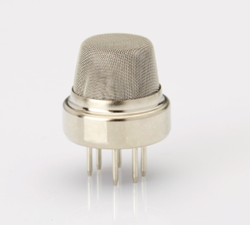
4. Smoke sensor solution
The MQ-2 smoke sensor is used in gas leakage detectors in homes and factories to measure liquefied petroleum gas, benzene, alkane, alcohol, hydrogen, smoke, and more.
-
Electrical specifications are as follows:
Product model MQ-2 Product type Semiconductor gas sensor Standard package Bakelite, with a metal cover Target gas Combustible gas, smoke Detection concentration 300–10,000 ppm (combustible gas) Standard circuit conditions Circuit voltage Vc ≤ 24V DC Heating voltage VH 5.0V ± 0.1V AC or DC Load resistance RL Adjustable Gas sensor features under standard test conditions Heating resistance RH 29 ± 3Ω (room temperature) Heating power consumption PH ≤ 950 mW Sensitivity S Rs (in air)/Rs (2,000 ppm C3H8) ≥ 5 Output voltage Vs 2.5–4.0V (in 2,000 ppm C3H8) Concentration slope α ≤ 0.6 (R3000 ppm/R1000 ppm C3H8) Standard test conditions Temperature and humidity 20°C ± 2°C, 55% ± 5% RH Standard test circuit Vc: 5.0V ± 0.1V VH: 5.0V ± 0.1V Preheating time Not less than 48 hours Oxygen content Recommended 21% and not less than 18%. The oxygen concentration affects the initial value, sensitivity, and repeatability. Consult Tuya Smart when you use it under low oxygen concentration. Service life 10 years -
Sensor sensitivity
For more information about sensor sensitivity, see the attachment.
To reduce the development cycle, the MQ-2 smoke sensor module is purchased.

Schematic diagram of the module:
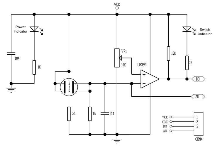
As seen from the figure, you can determine the smoke status by detecting the voltage on the AO channel. The higher the voltage, the higher the smoke concentration.
5. Gas sensor solution
The MQ-4 gas sensor can detect methane and natural gas with high sensitivity. It is widely used in household gas alarms, industrial combustible gas alarms, and portable gas detectors.
-
Electrical specifications are as follows:
Product model MQ-4 Product type Semiconductor gas sensor Standard package Bakelite, with a metal cover Target gas Methane Detection concentration 300–10,000 ppm (methane) Standard circuit conditions Circuit voltage Vc ≤ 24V DC Heating voltage VH 5.0V ± 0.1V AC or DC Load resistance RL Adjustable Gas sensor features under standard test conditions Heating resistance RH 29 ± 3Ω (room temperature) Heating power consumption PH ≤ 950 mW Sensitivity S Rs (in air)/Rs (in 5,000 ppm methane) ≥ 5 Output voltage Vs 2.5–4.0V (in 5,000 ppm CH4) Concentration slope α ≤ 0.6 (R5000 ppm/R1000 ppm CH4) Standard test conditions Temperature and humidity 20°C ± 2°C, 55% ± 5% RH Standard test circuit Vc: 5.0V ± 0.1V VH: 5.0V ± 0.1V Preheating time Not less than 48 hours Oxygen content Recommended 21% and not less than 18%. The oxygen concentration affects the initial value, sensitivity, and repeatability. Consult Tuya Smart when you use it under low oxygen concentration. Service life 10 years -
Sensor sensitivity
For more information about sensor sensitivity, see the attachment.
To reduce the development cycle, the MQ-4 gas sensor module is purchased. The schematic diagram of this module is the same as that of the MQ-2 smoke sensor module. The gas concentration can be determined by detecting the voltage on the AO channel. The higher the voltage, the higher the gas concentration.
5. Flame detection solution
An IR receiver diode is used to detect fire sources or heat sources with a wavelength in the range of 700 to 1000 nm.
- When there is no infrared light, there is a small saturated reverse leakage current (dark current), and the phototube does not conduct the current.
- When there is infrared light, the saturated reverse leakage current immediately increases to form a photocurrent. In a certain range, the photocurrent increases with the incident light intensity.
To reduce the development cycle, a common flame sensor module is purchased.
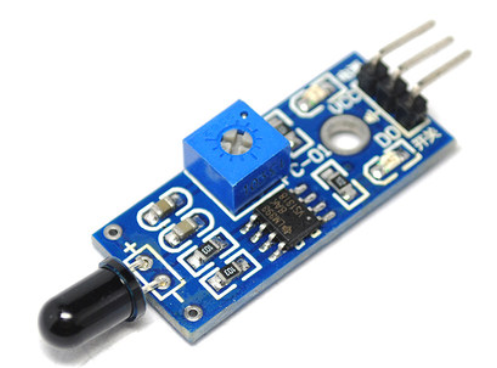
The schematic diagram is as follows.

The fire status is determined by detecting the voltage on the AO channel. The lower the voltage, the more fierce the fire.
6. Explore application scenarios
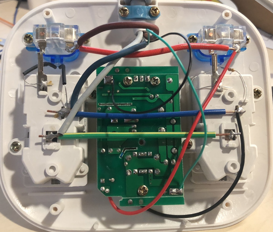
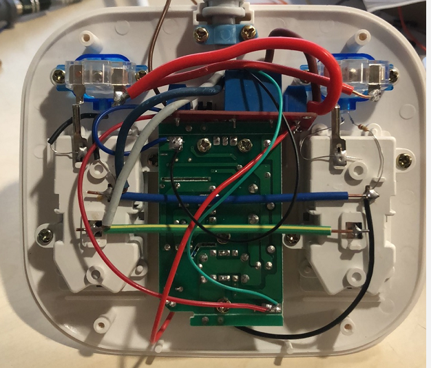
We choose and modify a socket with a table lamp, making the product more powerful.
Fix the environment monitor on the desk lamp stand. While detecting the air quality in the room, it can also detect whether the devices connected to the socket have fire hazards. For example, send alerts to users about safety hazards caused by devices containing lithium batteries, such as mobile phones.

You can also link the environment monitor with other devices.
Connect a 1-channel relay module to the desk lamp. When an anomaly occurs, the 220V power grid is automatically disconnected to reduce losses.
Step 2: Build the hardware
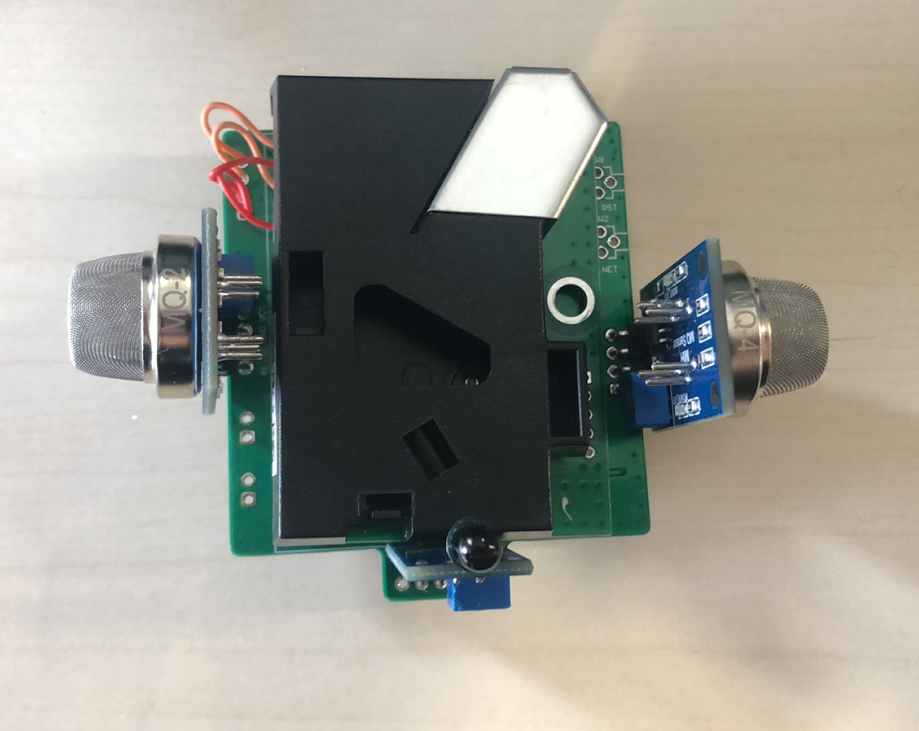
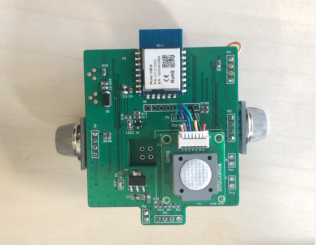
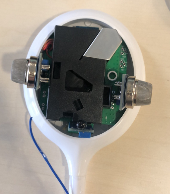
1. Assemble the sensors
Since the adapter board has already been designed, this step is relatively simple. You only need to insert each sensor module into the appropriate position according to the layout, and complete the welding and fixing.
To simplify the trace, you can directly solder the VCC, GND, and TXD of the formaldehyde sensor to the VCC, GND, and RXD of P5. The same is true for other sensors.
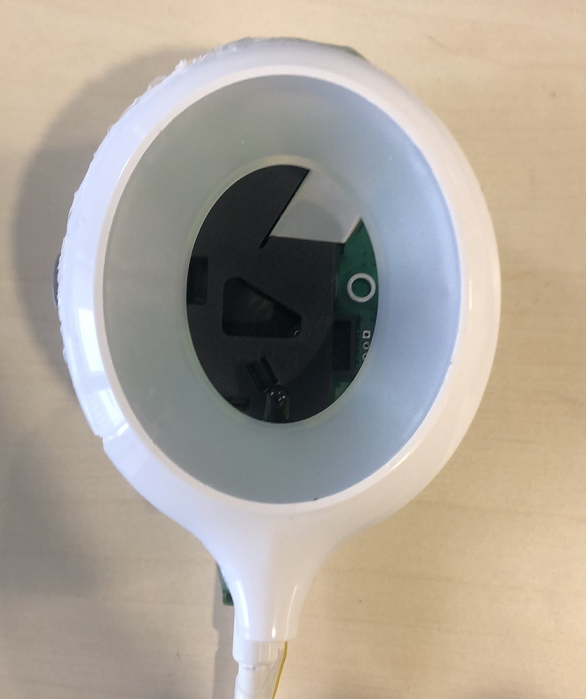
2. Assemble the device
-
Remove the lampshade, and you can see the LED lamp board and positive and negative power cords inside. Then, remove the LED lamp board with tools such as an electric soldering iron.
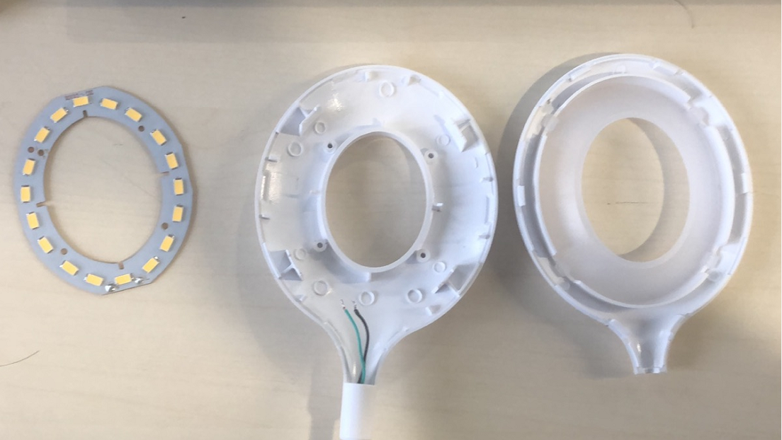
-
Remove the four sponge pads and the screws to remove the base.
-
Fix the master control board at the appropriate position in the lampshade area, and solder the positive and negative power cables to the P6 terminal on the master control board. When you press the desk lamp button on the socket, the socket can provide 5V voltage to the master control board. Pay attention to the positive and negative electrodes.
-
Modify the lamp circuit, put a relay in the live wire circuit, and break out the relay control pin.
-
Solder the control cable from the previous step to the Sig of the master control board P2, and install the lampshade and base.
You can explore creative ideas to decorate the lamp.
Step 3: Create a smart product on the Tuya IoT Platform
-
Log in to the Tuya IoT Platform, and click Create.
- Category: Sensors > Multi-function Sensor.
- Solution: Custom Solution.
- Protocol: WiFi+Bluetooth.

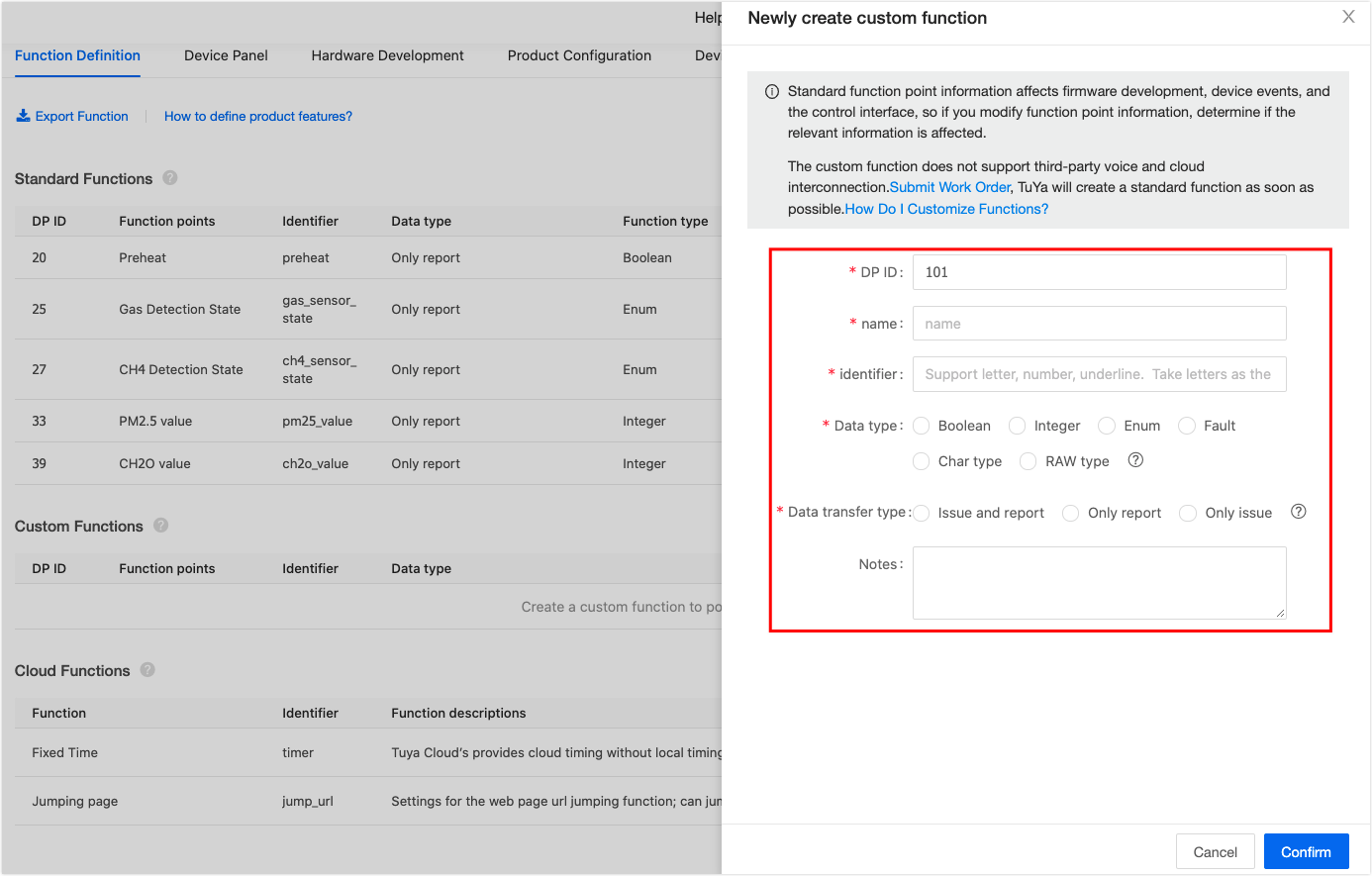
-
Select your desired functions.
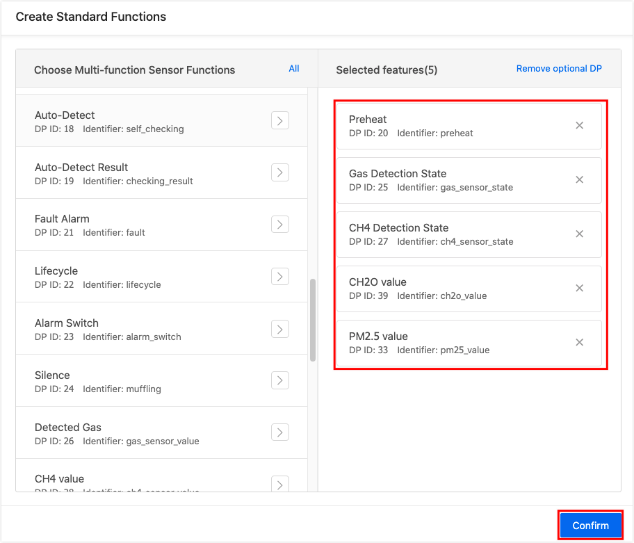
If you have not found the desired functions, you can click Create Functions in the Custom Functions area to customize the functions.
-
Select the device panel. The debugging panel can be used when you start debugging. You can configure the panel as you want.
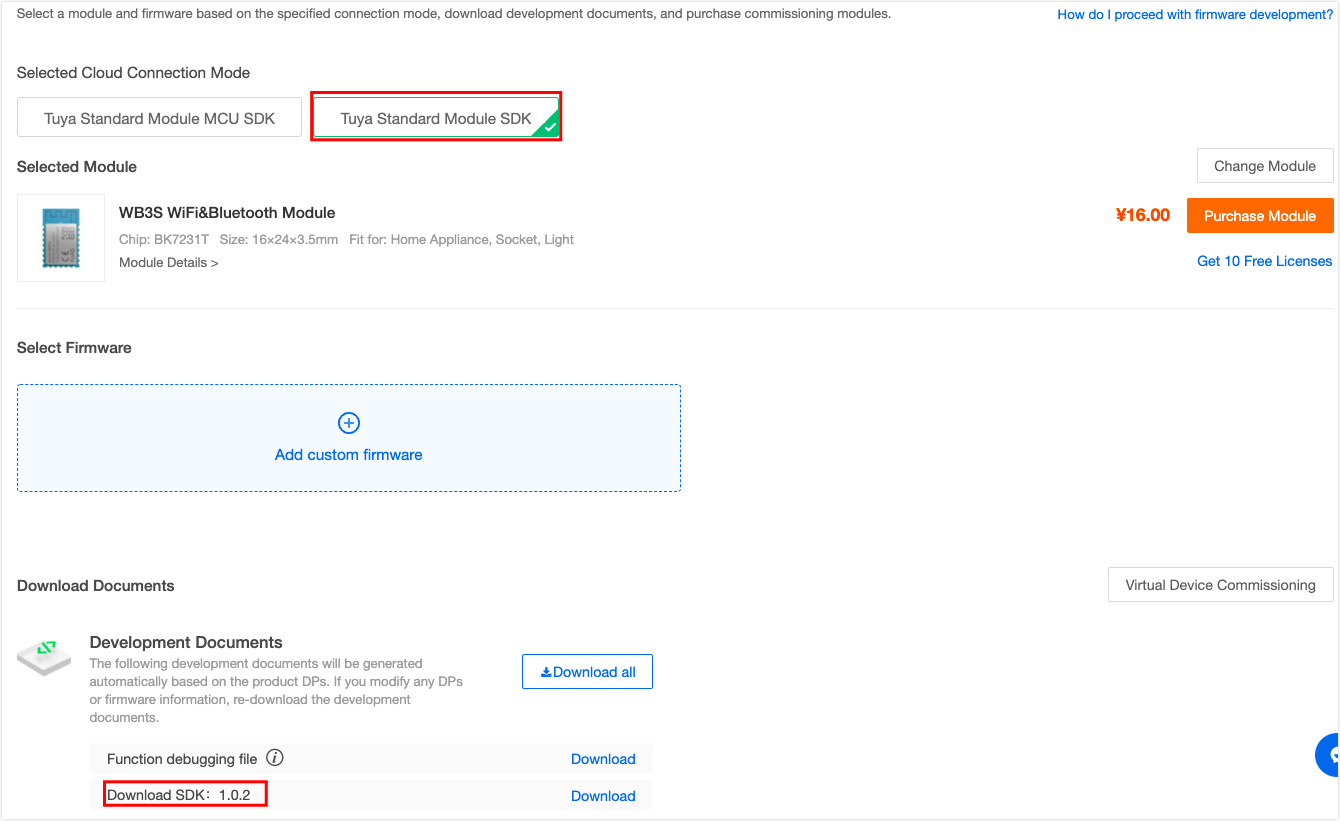
-
Select the development method and download the SDK and related files. In this demo, we select SDK development and use the WB3S module.
Step 4: Build the firmware
The demo code is developed based on the SDK of the v1.0.2 protocol. If you are new to SoC development, you can pull the code from the Tuya GitHub Repo for learning and development. You can code based on the relatively simple apps/template-demo.
This demo gets the information about the sensors through three methods: serial port, ADC, and level detection of the pins. The three methods are described as follows.
1. Sensors with serial ports (formaldehyde sensor and PM2.5 sensor)
According to the formaldehyde sensor documentation, we can find that the sensor data upload format and calculation method are as follows:
/***********************************************************
 *   Function: get_ch2o_sensor_value
 *   Input: none
 *   Output: none
 *   Return: none
 *   Notice: get and upload formaldehyde data
 ***********************************************************/
 static VOID get_ch2o_sensor_value(VOID)
 {
    UINT_T  buff_ret, find_head_index = 0;
    // High and low bits of formaldehyde data
    UCHAR_T ch2o_data_high, ch2o_data_low;
    // Checksum
    UCHAR_T check_sums = 0x00;
    // Serial data buffer
    UCHAR_T ch2o_receive_buffer[CH2O_BUFFER_SIZE];
    // Point to the formaldehyde data header
    UCHAR_T *p_ch2o_value = NULL;

    memset(ch2o_receive_buffer, 0, sizeof(ch2o_receive_buffer));

    // Read serial port data
    bk_uart_recv(CH2O_SENSOR_UART, ch2o_receive_buffer, CH2O_BUFFER_SIZE, 0xFFFF);

    // for (find_head_index = 0; find_head_index<CH2O_BUFFER_SIZE; find_head_index++) {
    //     PR_NOTICE("ch2o_receive_buffer[%d] = %02x", find_head_index, ch2o_receive_buffer[find_head_index]);
    // }

    // Look for the header sent by the CH2O sensor
    for (find_head_index = 0; find_head_index<CH2O_BUFFER_SIZE; find_head_index++) {
        if (ch2o_receive_buffer[find_head_index] == 0xff && \
            ch2o_receive_buffer[find_head_index+1] == 0x17 && \
            ch2o_receive_buffer[find_head_index+2] == 0x04){
            //PR_NOTICE("find head is %d", find_head_index);
            break;
        }
    }

    // The data collected is incomplete
    if (find_head_index > 11) {
        PR_ERR("ch2o get uart data no complete!" );
        return;
    }

    // Point to the header in the CH2O data
    p_ch2o_value = ch2o_receive_buffer + find_head_index;

    // Checksum. Confirm the accuracy of the data read
    check_sums = ch2o_check_sum(p_ch2o_value, 9);
    if (check_sums ! = *(p_ch2o_value + 8)) {
        PR_ERR("ch2o check_sums error");
        return;
    }

    ch2o_data_high = *(p_ch2o_value+4);
    ch2o_data_low = *(p_ch2o_value+5);

    gs_air_box.ch2o_value = ch2o_data_high * 256 + ch2o_data_low;

    //PR_NOTICE("ch2o value is : %d .", gs_air_box.ch2o_value);

    // Upload CH2O data to the Tuya IoT Platform
    updata_dp_single(gs_air_box.dp_ch2o_value, PROP_VALUE, gs_air_box.ch2o_value);

   return;
}
The checksum is calculated as follows:
Checksum = (reversed (Byte1+Byte2+…+Byte7))+1.
 /***********************************************************
 *   Function: ch2o_check_sum
 *   Input: none
 *   Output: none
 *   Return: none
 *   Notice: formaldehyde data checksum
 ***********************************************************/
static UCHAR_T ch2o_check_sum(UCHAR_T *data, UCHAR_T len)
{
    UCHAR_T i, tempq = 0;
    data += 1; // Point to data[1]

   for(i=0; i<(len-2); i++)
    {
        tempq += *data;
        data++;
    }

   tempq = (~tempq) + 1;

   return (tempq);
}
The PM2.5 data can be obtained like the formaldehyde data.
2. ADC sensor (gas sensor and smoke sensor)
Click to download the PDF document.
There is only one ADC on the WB3S module, so we use the RS2255 chip for multiplexing. The pins are described as follows:
| A(PWM0/GPIOA_6) | B(PWM1/GPIOA_7) | ON CHANNEL(S) |
|---|---|---|
| 0 | 0 | A0 |
| 0 | 1 | A1 |
| 1 | 0 | A2 |
| 1 | 1 | A3 |
-
Initialize the ADC.
/* ADC */ static tuya_adc_dev_t tuya_adc; static VOID adc_init(VOID) { tuya_adc.priv.pData = Malloc(ADC_DATA_LEN * sizeof(USHORT_T)); // tuya_adc is always used, so the space is not released later. memset(tuya_adc.priv.pData, 0, ADC_DATA_LEN*sizeof(USHORT_T)); tuya_adc.priv.data_buff_size = ADC_DATA_LEN; // Set the data buffer size. } -
Collect the ADC.
/*********************************************************** * Function: get_adc_value * Input: none * Output: adc_value: the collected ADC value * Return: none * Notice: get the voltage value collected by the ADC ***********************************************************/ VOID get_adc_value(OUT USHORT_T* adc_value) { INT_T ret; if (adc_value == NULL) { PR_ERR("pm25_adc_value is NULL"); return; } memset(tuya_adc.priv.pData, 0, ADC_DATA_LEN*sizeof(USHORT_T)); ret = tuya_hal_adc_init(&tuya_adc); if (ret != OPRT_OK) { PR_ERR("ADC init error : %d ", ret); return; } ret = ret = tuya_hal_adc_value_get(ADC_DATA_LEN, adc_value); if (ret != OPRT_OK) { PR_ERR("ADC get value error : %d ", ret); } tuya_hal_adc_finalize(&tuya_adc); return; } -
Get data from the smoke sensor.
/* Smoke sensor */ /*********************************************************** * Function: get_smoke_sensor_value * Input: none * Output: none * Return: none * Notice: get and upload the smoke data, A1 ***********************************************************/ static VOID get_smoke_sensor_value(VOID) { USHORT_T smoke_adc_value; FLOAT_T smoke_volt; // Reuse the ADC to A1 tuya_gpio_write(RS2255_A, FALSE); tuya_gpio_write(RS2255_B, TRUE); tuya_hal_system_sleep(500); // Get the ADC value of the smoke sensor get_adc_value(&smoke_adc_value); //PR_NOTICE("smoke_adc_value : %d ", smoke_adc_value); // Calculate the actual voltage value smoke_volt = (smoke_adc_value / 4095.0) * 2.4 * 2; //PR_NOTICE("smoke_volt : %lf ", smoke_volt); // Check whether the alarm threshold is reached if (smoke_volt >= SMOKE_ALARM_LIM) { gs_air_box.smoke_state = ALARM; } else { gs_air_box.smoke_state = NORMAL; } // Upload the data updata_dp_single(gs_air_box.dp_smoke_state, PROP_ENUM, gs_air_box.smoke_state); //PR_NOTICE("get smoke value, updata..."); return; }Gas sensors work in a similar way as smoke sensors.
3. Detect the status of getting high and low levels of the pins (flame sensor)
The 220V power supply is disconnected after the flame sensor detects the flame, and connected again after the flame sensor is restarted, in order to prevent accidents.
/***********************************************************
 *   Function: get_smoke_sensor_value
 *   Input: none
 *   Output: none
 *   Return: none
 *   Notice: get and upload the flame data
 ***********************************************************/
static VOID get_flame_sensor_value(VOID)
{
    if (FALSE == tuya_gpio_read(FLAME_SENSOR_PIN)) {
        gs_air_box.flame_state = ALARM;
        /* Detect a flame, pull down 220V control pin, and power off */
        tuya_gpio_write(POWER_OFF_220V_PIN, FALSE);
    } else {
        gs_air_box.flame_state = NORMAL;
    }

    updata_dp_single(gs_air_box.dp_flame_state, PROP_ENUM, gs_air_box.flame_state);

    return;
}
4. Initialize the device
During starting, initialize the peripherals and pins related to the environment monitor, create a semaphore, preheat the sensor, release the semaphore after the preheating is completed, and then start collecting.
/***********************************************************
 *   Function: air_box_device_init
 *   Input: none
 *   Output: none
 *   Return: none
 *    Notice: Initialize the device
 ***********************************************************/
 VOID air_box_device_init(VOID)
{
    INT_T opRet = OPRT_OK;

    /* Initialize the flame sensor peripherals */
    tuya_gpio_inout_set(FLAME_SENSOR_PIN, TRUE);
    tuya_gpio_inout_set(POWER_OFF_220V_PIN, FALSE);
    /* During starting, pull up the 220V control pin and power on */
    tuya_gpio_write(POWER_OFF_220V_PIN, TRUE);

    /* ADC multiplexing and pin initialization */
    tuya_gpio_inout_set(RS2255_A, FALSE);
    tuya_gpio_inout_set(RS2255_B, FALSE);
    adc_init();

    /* The formaldehyde sensor uses UART2 to receive data, and the baud rate has been modified in the app_init() function */

    /* Initialize the serial port of PM2.5 sensor */
    ty_uart_init(PM25_SENSOR_UART, TYU_RATE_9600, TYWL_8B, TYP_NONE, TYS_STOPBIT1, (PM25_BUFFER_SIZE * SIZEOF(UCHAR_T)), TRUE);

    /* Create semaphore */
    opRet = tuya_hal_semaphore_create_init(&preheat_semaphore, 0, 1);
    if (opRet ! = OPRT_OK) {
        PR_ERR("creat preheat semaphore error : %d", opRet);
    }

    /* Release the semaphore after 60s preheating, and start to collect sensor data */
    opSocSWTimerStart(preheat_timer, SENSOR_PREHEAT_TIME, preheat_semaphore_post_task);

    xTaskCreate(acquire_data_task, "acquire sensor data", 512, NULL, TRD_PRIO_2, NULL);
}
-
Release the semaphore after preheating:
VOID preheat_semaphore_post_task(VOID) { // Release the semaphore after preheating tuya_hal_semaphore_post(preheat_semaphore); // Turn off the preheating software timer opSocSWTimerStop(preheat_timer); // After the preheating is completed, upload the preheating completion data to the Tuya IoT Platform gs_air_box.preheat_state = false; updata_dp_single(gs_air_box.dp_preheat, PROP_BOOL, gs_air_box.preheat_state); } -
Polling tasks for collected data of the sensor:
/***********************************************************
 *   Function:  acquire_data_task
 *   Input: none
 *   Output: none
 *   Return: none
 *   Notice: a task to get sensor data
 ***********************************************************/
VOID acquire_data_task(VOID)
{
    // Wait for preheating to complete
    tuya_hal_semaphore_wait(preheat_semaphore);

    while (1) {
        get_ch2o_sensor_value();
        get_flame_sensor_value();
        get_gas_sensor_value();
        get_pm25_sensor_value();
        get_smoke_sensor_value();
        tuya_hal_system_sleep(500);
    }
}
Step 5: Pair and control
1. Display the air conditions in real-time
After the flashing and authorization are completed, the device can be paired properly. For more information about flashing and authorization, see Burn and Authorize WB Series Modules.
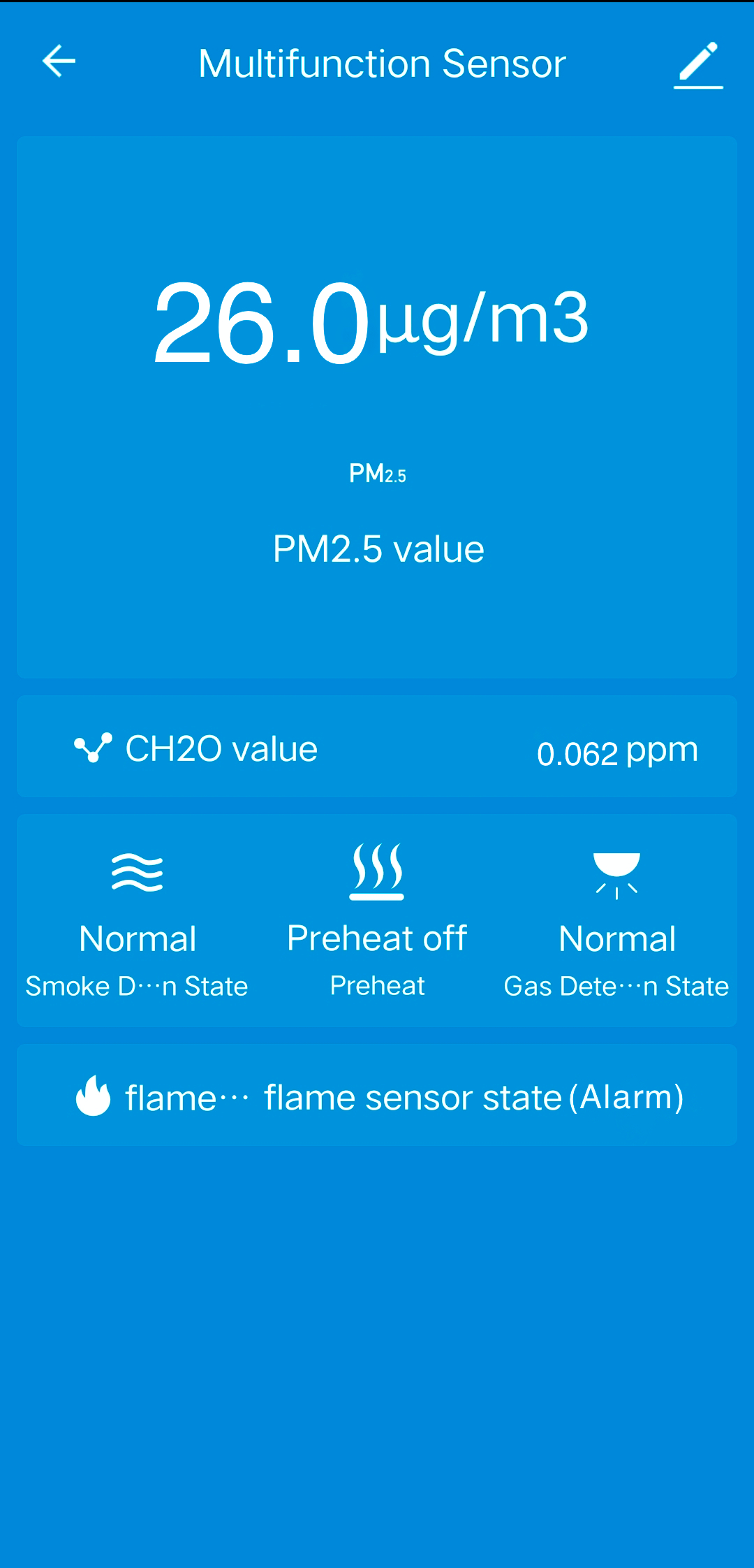
Connect the mobile phone to a Wi-Fi network, turn on Bluetooth, and pair the device as per the instruction. Then, we can control the device with the Tuya Smart app. After successful pairing, you can press and hold the button to enter the pairing mode again. The device panel on the app is shown as follows.

2. Alarm
If the concentration of one of smoke, gas or flame is greater than the set value, the Tuya Smart app will display the alarm status and disconnect the 220V power supply. The device panel on the app is shown as follows.
Is this page helpful?
YesSuggestions


