Prototype a Taste-Elevating Spoon
Overview
If you are a fitness fanatic on a low-calorie diet, your meal plan might list many tasteless foods. What if we have a special utility that can generate a mild electric current to stimulate the tongue and alter the taste, it will let you enjoy the flavor of low-calorie foods that contain less sugar and less salt. In this demo, we will show you how to make a taste-elevating spoon. Check out how we make this magic possible! Our spoon can process four flavors:
-
Sour: A 60 μA to 180 μA electric current can increase the temperature of the tongue from 20°C to 30°C.
-
Sweet: A reverse electric current can increase the temperature of the tongue to 35°C and then gently decrease it to 20°C.
-
Bitter: A reverse electric current from 60 μA to 140 μA.
-
Salty: A low-frequency electric current from 20 μA to 50 μA.
Steps
Step 1: Hardware design
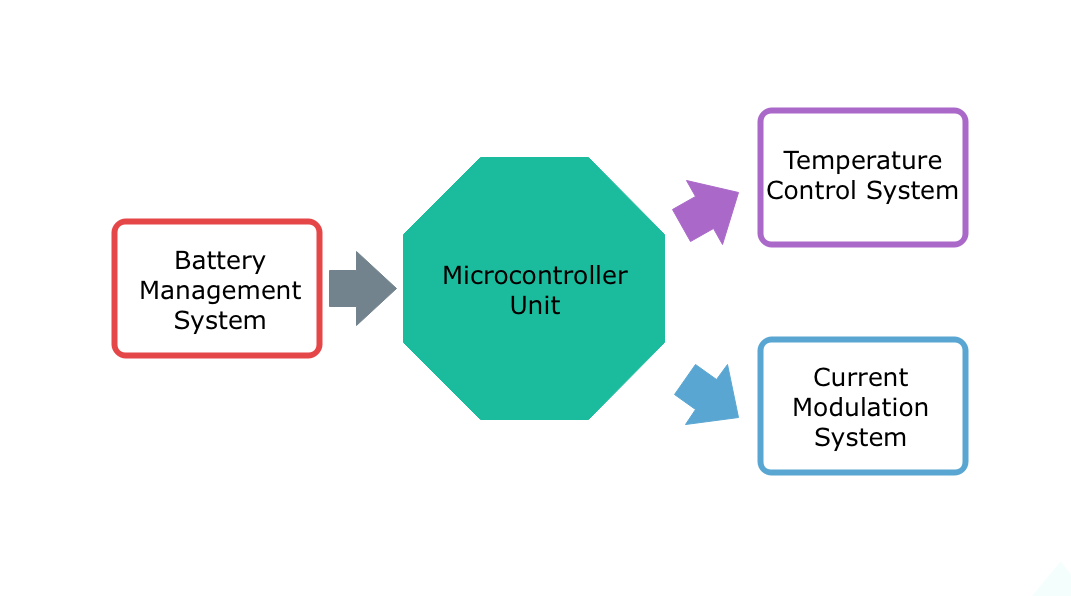
Microcontroller unit
We use a Bluetooth module from Tuya Smart as the microcontroller.
Battery management system
Considering the compact design of the spoon, we choose the lithium-ion battery that features high energy density, no memory effect, and low self-discharge.
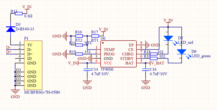
To better manage the battery charge and discharge for long service life, we design a battery management circuit.
We choose the TP4056 IC to charge the lithium-ion battery through the constant current/constant voltage (CC/CV) charging method. It uses the internal p-channel MOSFET architecture which eliminates the use of blocking diode. It prevents a negative charge current circuit. Thermal feedback regulates the charge current to limit the temperature during high power operation or high ambient temperature. The charge voltage is fixed at 4.2V, and the charge current is programmable externally with a single resistor. The chip automatically terminates the charge cycle when the charge current drops to 1/10th the programmed value after the final float voltage is reached.
Battery management circuit diagram
-
V_IN: It is the power supply pin, used to supply 5V through the USB connector. -
V_BAT: It is the battery connection pin connected to the positive terminal of the battery. Connect the negative terminal of the battery to the GND pin. -
CE: It is an input pin for enabling the chip into operation or disabling it. -
STDBY: When the battery is completely charged, this pin is pulled low by an internal switch. Otherwise, it is in a high impedance state. -
CHRG: Open drain charge status output. When the battery is charging, this pin is pulled low by an internal switch. Otherwise, it is in a high impedance state.Note: You can use a green LED and a red LED to indicate the charging state. The steady-on red LED indicates the battery is charging. The steady-on green LED indicates the standby mode.
-
PROG: Constant charge current setting and charge current monitoring pin. The charge current to the battery is set by connecting an external resistor between this pin and GND. In pre-charge mode, this pin’s voltage is regulated to 0.1V. In constant charge current mode, this pin’s voltage is regulated to 1V. The voltage on this pin in charge mode can be used to measure the charge current as follows:Ibat = 1,200 × Vprog/Rprog.Important:
- To prevent heating the IC and battery due to charging with a large current, we recommend you set the maximum charge current to 0.8A. With the above formula, we can have this
Rprog = 1,200 × Vprog/Ibat. - Assume that
Ibatis 0.8A andVprogis 1V. Then, theRprogwill be 1.5 kΩ. If you intend to increase the current, you can reduce theRprogresistor based on the calculatedRprogvalue.
- To prevent heating the IC and battery due to charging with a large current, we recommend you set the maximum charge current to 0.8A. With the above formula, we can have this
-
TEMP: Temperature sensing input. Connect this pin to the NTC thermistor’s output in the battery. If theTEMPpin’s voltage is below 45% or above 80% of supply voltage, this means that the battery’s temperature is too high or too low and charging will be suspended. The temperature sensing function can be disabled by grounding theTEMPpin.Note: To improve development efficiency, you can solder a zero-ohm resistor on R16 and R14 to disable the temperature sensing function. If you want to resume this feature, submit a service ticket for technical support.
For more information, see TP4056 Datasheet.
Current modulation system
This taste-elevating spoon combines electric stimulation and tongue sensory to generate a mild electric current to stimulate the tongue and alter taste. Therefore, we must design a reliable current modulation system.
The modulation system works for modulating current frequency and current intensity. The following diagram shows the modulation circuit.
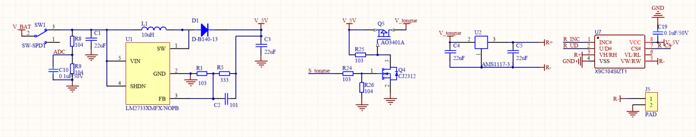
Since the lithium-ion battery can only supply 3.6V power but the digital potentiometer operates on 5V, we need a boost converter to step up the voltage.
Boost converter
The LM2733X series boost converter from Texas Instruments features a 40V DMOS FET switch, 1.6 MHz switching frequency, an output current of up to 1A, and wide input voltage ranging from 2.7V to 14V. For more information, see LM2733X Datasheet.
We need to modulate the resistance of R1 and R5 to output 5V voltage. According to the datasheet, LM2733X’s output voltage is calculated by
Vfb × (1+R5/R1). The typical value ofVfbis 1.23V. In this project, R1 is 10 kΩ and R5 is 33 kΩ. Therefore, the output voltage (Vout) should be 5.3V. You can step up the voltage to the required value, but the target voltage should not exceed 7V because the withstand voltage of the digital potentiometer is 7V. Otherwise, the potentiometer might be damaged.Modulate the current frequency
You can design a control circuit by using two MOSFETs of different types of channels.
- When
S_tongueoutputs high,Q5MOSFET is on-state to supply the circuit behind it. - When
S_tongueoutputs low,Q5MOSFET is cut-off to stop supplying the circuit behind it.
You can control the frequency of the load voltage by adjusting the pulse period and duty cycle of the signal
S_tongue, hence achieving current frequency modulation.Modulate the current intensity
We use a low-dropout (LDO) regulator and a digital potentiometer to modulate the current intensity.
-
U2is the AMS1117-33 LDO. It is a positive LDO regulator and integrated with over-temperature protection and a current limiting circuit. It can output up to 1A current, support up to 12V input voltage, and regulate the output voltage to 3.3V, with an output voltage tolerance of less than 1%. For more information, see AMS1117 Datasheet. -
U7is the X9C104SIZT1 digital potentiometer. It is fundamentally a programmable resistor to regulate the resistance by digital control. It features high precision, low noise, and good EMI suppression.The digital potentiometer consists of three sections: the input control, counter and decode section, the nonvolatile memory, and the resistor array. The input control section operates just like an up/down counter. The output of this counter is decoded to turn on a single electronic switch that connects a point on the resistor array to the wiper output. Under the proper conditions, the contents of the counter can be stored in nonvolatile memory and retained for future use. The resistor array is composed of 99 individual resistors connected in series. At either end of the array and between each resistor is an electronic switch that transfers the connection at that point to the wiper.
-
The
RhandRlpins are equivalent to the fixed terminals of a mechanical potentiometer. -
The
Rwpin is the wiper terminal of the potentiometer, which is equivalent to the movable terminal of a mechanical potentiometer. -
The
U/Dis the up/down control input pin. It controls the movement direction of the wiper terminal. -
The
INCinput is negative-edge triggered. TogglingINCwill move the wiper and either increment or decrement the counter in the direction indicated by the logic level on the U/D input.For more information, see X9C104SIZT1.
-
The principle of current intensity modulation
When the current modulation circuit operates, the voltage of
R+andR-terminals on the LDO isVref(3.3V). The resistance of these two terminals isRsof the resistor connected to theU7(digital potentiometer).Given this, we can get the following data:
- The current of
R+andR-terminals on the LDO isIs = Vref/Rs. - The total current flowing through the load is
I=Is+Iss.
Issis the quiescent leakage current of the LDO, flowing from the common terminal to the GND.Issvaries depending on the LDOs. However, since theIssis pretty small, the difference can be ignored.Hence, the total current can be
I ≈ Is = Vref/Rs.After LDO is determined, the
Vrefwill be a fixed value. You can alter the resistance ofRsthrough the program to adjust the output current.The current discharge is sent through
J5to stimulate the tongue and alter the taste.Temperature control system
The temperature control system consists of the heating function and temperature sensing. The schematic diagram is as follows.
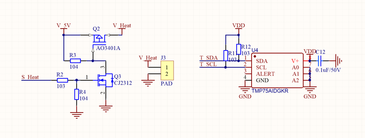
Heater component
We choose the commonly-used Polyimide heater. Polyimide is a thin, lightweight organic polymer film that provides excellent tensile strength, tear resistance, and dimensional stability. Polyimide heaters provide the thinnest profile of all flexible heaters and offer precise heat distribution. They work well in extreme heat environments or small spaces. You can stick the Polyimide heater on the PCB and solder the pin of the heater on
J3.Temperature sensing
Q2is the P-channel MOSFET.Q3is the N-channel MOSFET.- When
S_Heatoutputs high,Q2MOSFET is on-state. The heater onJ3starts heating the spoon. - When
S_Heatoutputs low,Q2MOSFET is cut-off. The heater onJ3stops heating the spoon.
We use the TIMP75 temperature sensor from Texas Instruments to measure the temperature change.
The TMP75 is a digital temperature sensor ideal for negative temperature coefficient (NTC) and positive temperature coefficient (PTC) thermistor replacement. It features SMBus™, two-wire, and I2C interface compatibility. It is specified for operation over a temperature range of -40°C to +125°C, with a typical accuracy of ±1°C. The TMP75 has a low quiescent current of 50 μA and consumes only 0.1 μA in standby mode. The device offers a typical accuracy of ±1°C without requiring calibration or external component signal conditioning. Device temperature sensors are highly linear and do not require complex calculations or look-up tables to derive the temperature. The on-chip 12-bit ADC converter offers resolutions down to 0.0625°C. For more information, see TMP75 Datasheet.
The circuit design is completed until then. The following links provide the complete schematic diagram and sample PCB design. You can add more features to your project such as LED, buttons, and USB connection as needed.
-
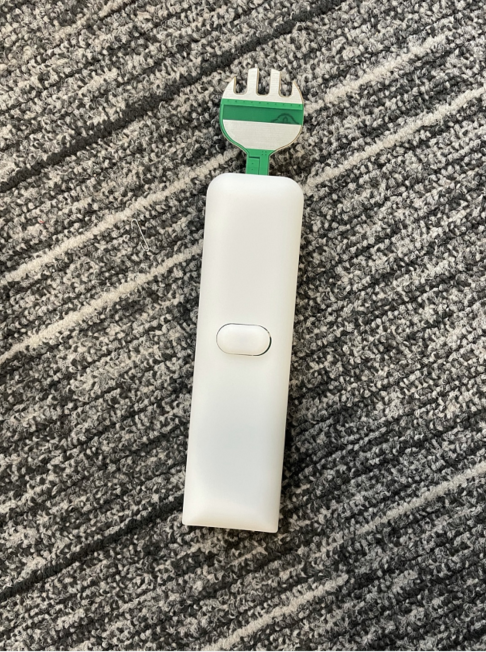
Step 2: Structural design
Step 3: Product creation
-
Log in to the Tuya IoT Development Platform.
-
Click Create.
-
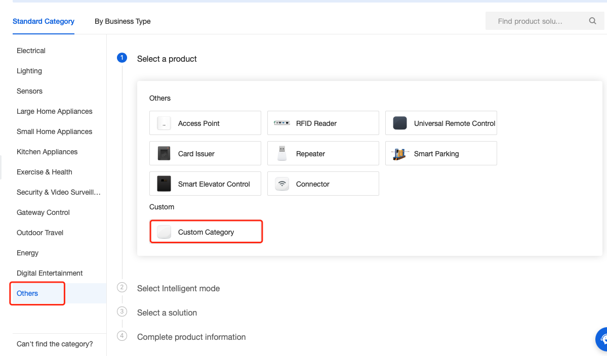
Scroll down the page and click Others in the lower-left corner. Select Custom Category > TuyaOS > Custom Solution.
-
Complete the required information and click Create.
-
Product Name, Product Description, and Product Model are user-defined.
-
Select Bluetooth as the protocol.
-
-
In the Function Definition tab, click Add to create required functions. You can add standard functions or create custom functions as needed.
We add five custom functions, namely low battery warning, flavors, current, frequency, and temperature. The following figure shows the data type and parameter specified for each function.

-
In the second step of the Device Panel tab, select the desired panel.
-
In the third step of Hardware Development, select TuyaOS.

-
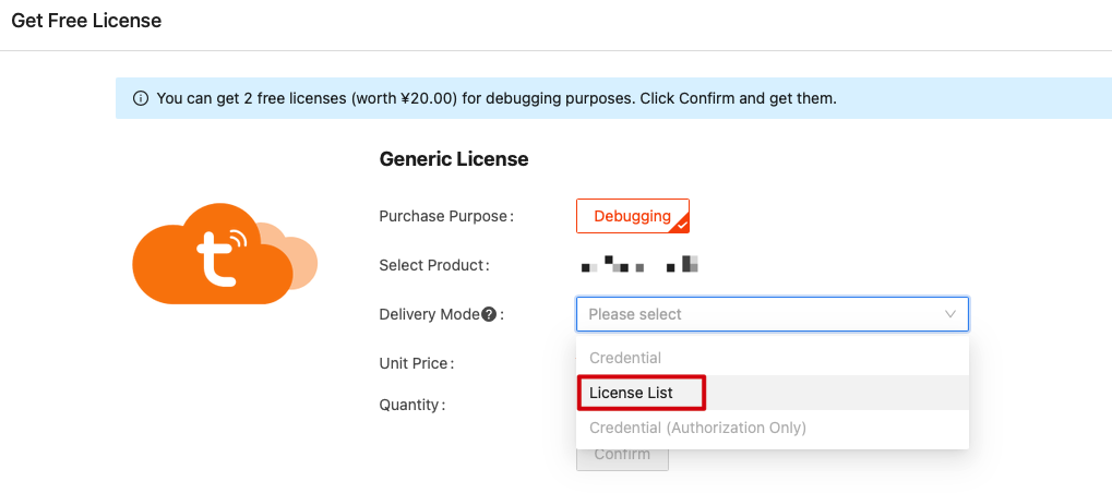
Select a module and then click Get 2 Free Licenses.
-
Select License List and download the list for later use.
-
Step 4: Software development
Features
Feature Description Notes Reset and pairing Quickly power on and off the spoon three times. Implemented by the power button. Battery level prompt Low battery warning. The mobile app prompts users with a low battery warning. Basic flavors Sour, sweet, bitter, and salty. Control the electric current, frequency, and temperature. User-defined The user can adjust the electric current, frequency, and temperature. These three parameters can be adjusted using the mobile app. Get the SDK
Download the Bluetooth Low Energy SDK. Make sure to read the README file to learn more about the flash partition, debugging pins, and baud rate.
Set up IDE
We use Telink IDE for development. Go IDE for TLSR8 Chips and download the IDE.

Edit and build project
-
Change the parameter of
Product_IDto the PID of your product created on the Tuya IoT Development Platform.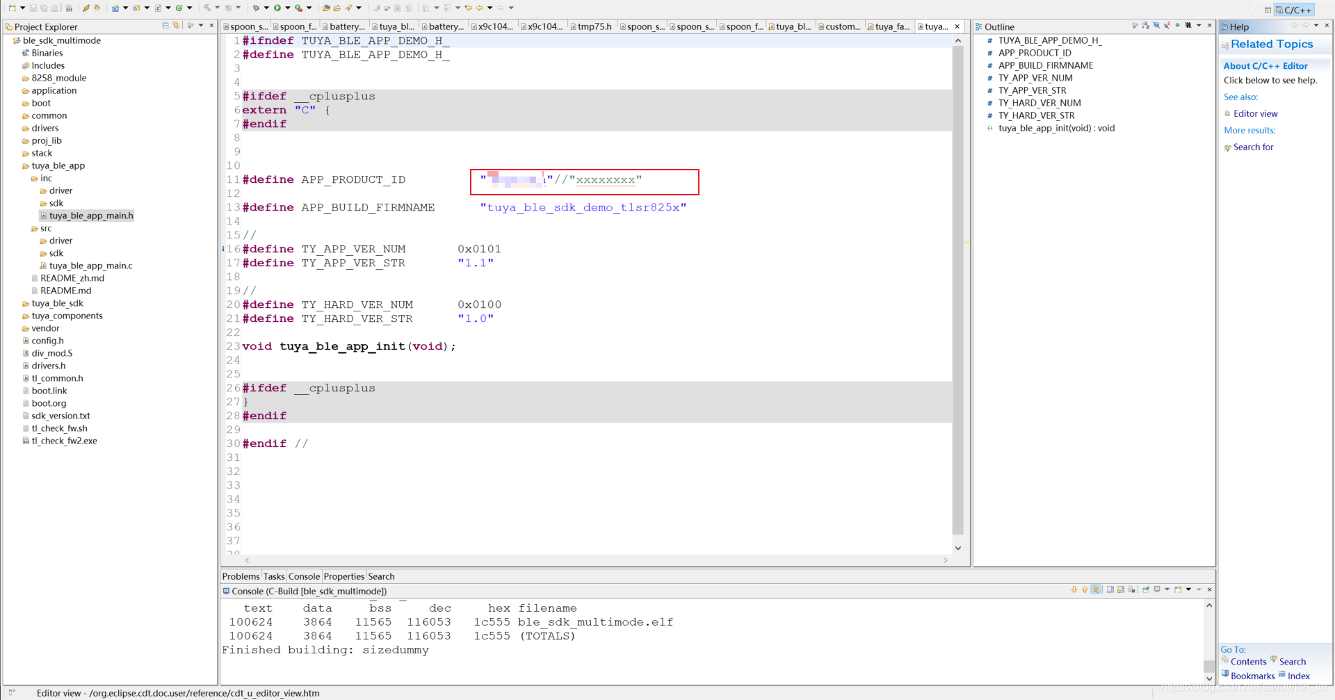
-
Update the
auth_key,device_id, andmacto the parameter provided on the license list.
-
Edit the function
void tuya_ble_app_init(void).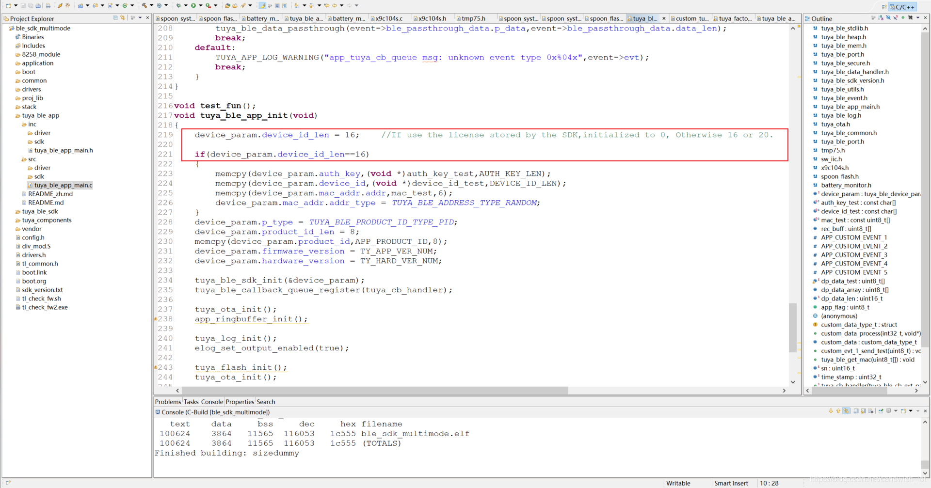
-
Build the project.
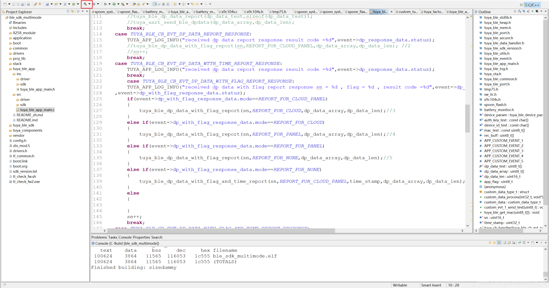
Feature implementation
Reset and pairing
The spoon has only one physical button, which is used for both the power button and reset button. Pressing the power button will power off the spoon instead of entering the sleep mode. To use this button for pairing, quickly power on and off the spoon three times to reset the spoon and make it enter the pairing mode. After successful pairing, the spoon can be connected again. To bind the spoon with another app account, you must remove the spoon from the app logged in with the current account and pair it using the new account.
How pairing works
Set a pairing flag. Write the flag to the flash memory after the first-time power on and off, add one to the current flag after the second-time power on and off, and so on. At the same time, start a timer and specify the valid time to an expected time period during which pairing can be completed. After the timer expires, the flags are will be cleared.
tuya_ble_device_factory_reset()is called after the third-time power on to reset the spoon for entering the pairing mode. You can add an LED to indicate the pairing status. Quick blinking indicates the spoon is ready for pairing. A steady-on state indicates the spoon is paired. The implementation code:// Clear the pairing flags from the flash memory. static int clear_ble_flag(void) { Flash_Write_Buff[0] = 0; flash_erase_sector(FLASH_ADDR); flash_write_page(FLASH_ADDR, FLASH_BUFF_LEN, (unsigned char *)Flash_Write_Buff); blt_soft_timer_delete(&clear_ble_flag); return 0; } //Power on and off the spoon three times. uint8_t switch_setup_network(void) { blt_soft_timer_add(&clear_ble_flag, 5000*TIME_MS); // Clear the pairing flags from the flash memory five seconds after the spoon is paired. flash_read_page(FLASH_ADDR, FLASH_BUFF_LEN, (unsigned char *)Flash_Read_Buff); Flash_Write_Buff[0] = Flash_Read_Buff[0]; TUYA_APP_LOG_INFO("Flash_Read_Buff[1] = %d", Flash_Read_Buff[0]); // Power on and off the spoon three times. if (Flash_Read_Buff[0] < POWER_COUNT) { Flash_Write_Buff[0]++; flash_erase_sector(FLASH_ADDR); flash_write_page(FLASH_ADDR, FLASH_BUFF_LEN, (unsigned char *)Flash_Write_Buff); } else { TUYA_APP_LOG_INFO("start connect new device"); tuya_ble_device_factory_reset(); // Disconnect from the spoon to enter the pairing mode. The binding information will be cleared. } return Flash_Write_Buff[0]; }void led_connect_status(void) // Determine the network status to feed it back to the LED for indicating. This function is called in loop. { if (BONDING_CONN == status_flag) { gpio_write(BLE_LED_PIN, 0); } else { if (clock_time_exceed(time_tick, TIME_MS * 400)) { time_tick = clock_time(); gpio_toggle(BLE_LED_PIN); } } }switch_setup_network()is called in the initialization process.led_connect_status()is called in the loop.Battery level prompt
Read the battery voltage through the ADC. If the battery only has 10% left (the battery voltage is 3.5V), the mobile app will send a low battery warning.
get_battery_value()is called in the loop to collect the battery voltage every 10 seconds./ ADC sampling frequency is 14-bit. The reference voltage is 1.2V. static unsigned int get_adc_value(void) { adc_init(); adc_base_init(BATTERY_ADC_PORT); adc_power_on_sar_adc(1); return adc_sample_and_get_result(); } // Collect the battery voltage. unsigned short get_battery_value(void) { if (!clock_time_exceed(battery_time_tick, TIME_MS*10000)) { return 0; } battery_time_tick = clock_time(); unsigned int battery_adc_value = 0; battery_adc_value = get_adc_value() * 2; // Voltage divider. The total battery voltage = 2 × `battery_adc_value` if (battery_adc_value <= BATTERY_ADC_LOWER_LIMIT) { // The mobile app sends a low battery warning when the battery has only 10% left. power_alarm_buf[3] = ALARM; tuya_ble_dp_data_report(power_alarm_buf, DP_BUF_LEN); // Report the low battery status. } else { power_alarm_buf[3] = NORMAL; tuya_ble_dp_data_report(power_alarm_buf, DP_BUF_LEN); } TUYA_APP_LOG_INFO("battery_val = %dmv", battery_adc_value); return battery_adc_value; }Flavors
The flavor feature provides four basic flavors and one user-defined flavor. The mobile app sends the flavor-altering command to control the heater and output the target microcurrent to stimulate the tongue and alter the taste. The microcurrent is implemented by adjusting the resistance through X9C104SIZT1 digital potentiometer.
The user-defined flavor allows creating the desired flavor by saving the target current, frequency, and temperature.
void app_dp_handle(uint8_t *dp_data) { TUYA_APP_LOG_INFO("dp_data:%d %d %d %d", dp_data[0], dp_data[1], dp_data[2], dp_data[3]); switch (dp_data[0]) { // The four flavors: sour, sweet, bitter, and salty. case 0x66: switch (dp_data[3]) { case sour: spoon_state.temp = sour_temp; blt_soft_timer_delete(&sweet_temp_contorl); blt_soft_timer_delete(&bitter_temp_contorl); gpio_write(TONGUE_PIN, 1); x9c104s_set(_140uA); // blt_soft_timer_add(&sour_temp_contorl, 200*TIME_MS); break; case sweet: spoon_state.temp = heat_off; // blt_soft_timer_delete(&sour_temp_contorl); blt_soft_timer_delete(&bitter_temp_contorl); gpio_write(TONGUE_PIN, 1); x9c104s_set(_80uA); blt_soft_timer_add(&sweet_temp_contorl, 200*TIME_MS); break; case bitter: spoon_state.temp = heat_off; // blt_soft_timer_delete(&sour_temp_contorl); blt_soft_timer_delete(&sweet_temp_contorl); gpio_write(TONGUE_PIN, 1); x9c104s_set(_100uA); blt_soft_timer_add(&bitter_temp_contorl, 200*TIME_MS); break; case salty: spoon_state.temp = heat_off; // blt_soft_timer_delete(&sour_temp_contorl); blt_soft_timer_delete(&sweet_temp_contorl); blt_soft_timer_delete(&bitter_temp_contorl); x9c104s_set(_60uA); blt_soft_timer_add(&set_tongue_Hz, _hz100); break; case user_defined: // blt_soft_timer_sour_tempdelete(&sour_temp_contorl); blt_soft_timer_delete(&sweet_temp_contorl); blt_soft_timer_delete(&bitter_temp_contorl); x9c104s_set(_60uA); blt_soft_timer_add(&set_tongue_Hz, _hz100); break; default: break; } break; // Current adjustment, available for user-defined mode. case 0x67: switch (dp_data[3]) { case uA_20: x9c104s_set(_20uA); break; case uA_40: x9c104s_set(_40uA); break; case uA_60: x9c104s_set(_60uA); break; case uA_80: x9c104s_set(_80uA); break; case uA_100: x9c104s_set(_100uA); break; case uA_120: x9c104s_set(_120uA); break; case uA_140: x9c104s_set(_140uA); break; case uA_180: x9c104s_set(_180uA); break; case uA_200: x9c104s_set(_200uA); break; default: break; } break; // Frequency adjustment, available for user-defined mode. case 0x68: switch (dp_data[3]) { case hz_50: blt_soft_timer_add(&set_tongue_Hz, _hz50); break; case hz_100: blt_soft_timer_add(&set_tongue_Hz, _hz100); break; case hz_200: blt_soft_timer_add(&set_tongue_Hz, _hz200); break; case hz_400: blt_soft_timer_add(&set_tongue_Hz, _hz400); break; case hz_600: blt_soft_timer_add(&set_tongue_Hz, _hz600); break; case hz_800: blt_soft_timer_add(&set_tongue_Hz, _hz800); break; case hz_1000: blt_soft_timer_add(&set_tongue_Hz, _hz1000); break; case hz_0: blt_soft_timer_delete(&set_tongue_Hz); gpio_write(TONGUE_PIN, 1); break; default: break; } break; // Temperature adjustment, available for user-defined mode. case 0x69: switch (dp_data[3]) { case T_30: break; case T_31: spoon_state.temp = temp_31; break; case T_32: spoon_state.temp = temp_32; break; case T_33: spoon_state.temp = temp_33; break; case T_34: spoon_state.temp = temp_34; break; case T_35: spoon_state.temp = temp_35; break; case T_36: spoon_state.temp = temp_36; break; case T_37: spoon_state.temp = temp_37; break; case T_38: spoon_state.temp = temp_38; break; case T_39: spoon_state.temp = temp_39; break; case T_40: spoon_state.temp = temp_40; break; default: break; } break; default: break; } }-
Step 5: Flashing and authorization
For more information, see Bluetooth Low Energy Module Flashing and Authorization.
Summary
The Tuya IoT Development Platform provides convenient IoT development tools and services, which are designed to make your IoT project much easier and efficient. Check it out and discover more awesome ideas.
Is this page helpful?
YesSuggestions


