Prototype a Creative Vending Machine
Overview
Thanks to innovative technologies, our lifestyle becomes more efficient and smarter. The simple vending machine is one of the great inventions of the modern age. It is an efficient and low-cost method used by suppliers to deliver products to end-users around the clock, 24/7.
This tutorial will show you how to prototype a vending machine in a low-code approach based on Tuya’s LZ201 Cat.1 module and MCU SDK.
Materials
74HC165
Count:18-bit parallel-input and serial-output shift register, used to determine motor rotation direction.more
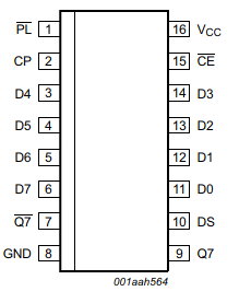
74HC595
Count:28-bit serial-input and parallel-output shift register, used to output the control signal to motors.more
FDS9945
Count:10N-channel MOSFET used to drive the motor.more
FDS9958
Count:10P-channel MOSFET used to drive the motor.more
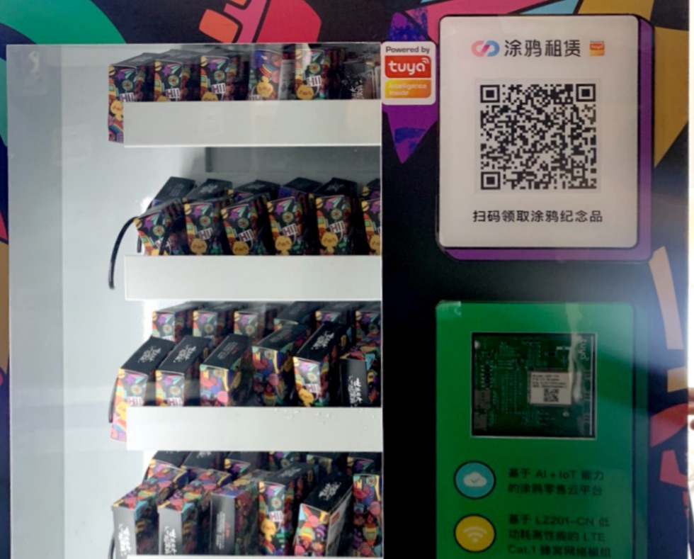
LZ201-CN
Count:1Tuya's LZ201-CN Cat.1 cellular module can establish communication between the vending machine and the Tuya IoT Cloud.more
STM32
Count:1Microcontroller IC used to control the system.more
Motor
Count:10The gear motor used to control a product falling.
ST-LINK
Count:1An in-circuit debugger and programmer for the STM32 microcontroller.more
Steps
Step 1: Hardware design
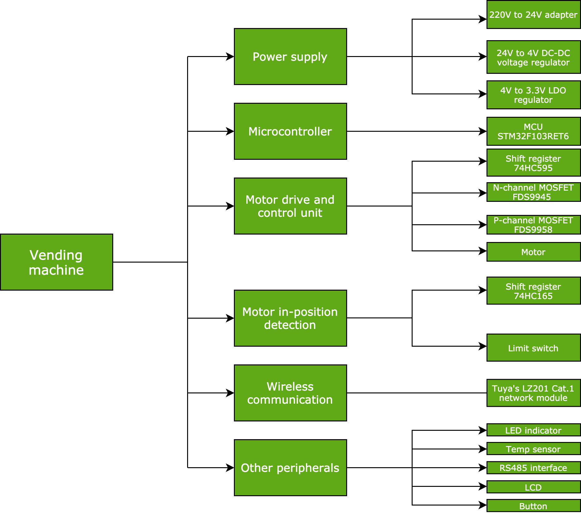
The hardware consists of the power supply unit, microcontroller unit (MCU), motor drive and control unit, motor in-position detection unit, wireless communication unit, and other peripheral units. The block diagram is as follows.
Power supply unit
Three units need power supply:
- Main power: 24V DC power supply. Connect it to the MOSFET to supply power to the motor of the vending machine.
- Wireless communication unit: 4V DC power supply. Use LM2576 DC-DC voltage regulator IC to step down 24V to 4V. LM2576 can drive a 3A load with excellent line and load regulation.
- MCU: 3.3V power supply. Use S-1206B33-U3T1G low-dropout (LDO) regulator IC to step down 4V to 3.3V.
MCU
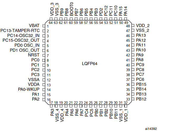
STM32F103RET6 is a 32-bit high-density performance MCU. It incorporates ARM Cortex-M3 architecture, operating at a 72 MHz frequency. It features 11 timers and an internal reset circuit, voltage detector, voltage regulator, and trimmed RC oscillator. For more information about the product and datasheet, see the STM32F103RE Overview and STM32F103RE Datasheet respectively.
Motor drive and control unit
Components
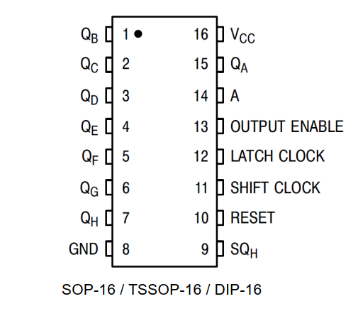
74HC595 is an 8-bit serial-input and parallel-output shift register, used to output the control signal to motors. (74HC595 Datasheet)
Connect each terminal of a motor to an FDS9945 n-channel MOSFET (FDS9945 Datasheet) and an FDS9958 p-channel MOSFET (FDS9958 Datasheet) respectively. The connection method is as follows:
- Regarding the three terminals of the FDS9958 MOSFET, connect the source to the 24V power supply, the gate to the signal wire, and the drain to the positive terminal of the motor.
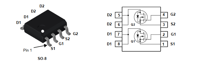
- Regarding the three terminals of the FDS9945 MOSFET, connect the source to the ground, the gate to the signal wire, and the drain to the negative terminal of the motor.
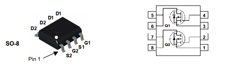
When FDS9945 and FDS9958 are both in the on-state, the motor can rotate.
Component quantity
- Signal wire: 11 pieces. We design 10 product trays, which require 10 motors. Typically, we need 20 pieces of the signal wire. If we connect the negative terminals of the 10 motors to the drain on the FDS9945 MOSFET with one signal wire. Only 11 pieces of wire are needed.
- 74HC595 shift register: two pieces connected in series. We have 11-bit data to be input and output but one shift register only supports 8-bit data. Therefore, we connect the two shift registers in series, and up to 16-bit data is supported.
Motor in-position detection unit
74HC165 is an 8-bit parallel-input and serial-output shift register, used to determine motor rotation direction. (74HC165 Datasheet)
When the motor rotates to a specified position, the limit switch outputs a low-level signal to the parallel input pin on the 74HC165 shift register. The MCU can read data from the serial output pin on the 74HC165. When the MCU detects a low level of a bit, it will stop the corresponding motor.
Since we do not have enough I/Os, the 10 motors can share the same limit switch.
Wireless communication unit
Tuya’s proprietary LZ201-CN Cat.1 cellular module can establish communication between the vending machine and the Tuya IoT Cloud. For more information, see LZ201-CN Cat.1 Module Datasheet.
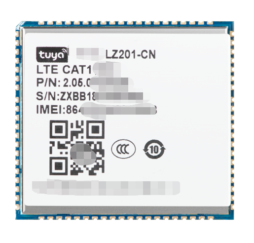
This module consists of a highly integrated LTE Cat.1 chip UIS8910DM and peripheral circuits. It features:
- Built-in LTE Cat.1 network communication protocol stack and library functions.
- Embedded Cortex-A5 processor and Cat.1bis modem.
- Flash memory up to 64 MB and SRAM up to 128 MB.
- Supported pins including USB, UART, SDIO, SPI, I2C, I2S, and ADC.
- Supported peripherals including display, camera, keyboard matrix, microphone, speaker, charger, microSD card, and USIM card.
Simply porting Tuya’s MCU SDK, you can enable the vending machine to be connected to the cloud and implement device control with an app. You can also opt for the WB3S Wi-Fi module or modules of other communication protocols.
Other peripheral units
The following lists some of the optional peripherals:
- LED to indicate network status.
- LED to indicate power status.
- Temperature sensor to detect the temperature in the vending machine.
- Falling detector to detect product falling and return the result of the operation.
- Multi-channel buttons to trigger specific button-press actions.
- RS-485 interface to build communication between the vending machine and RS-485 devices.
- LCD for human-machine interaction.
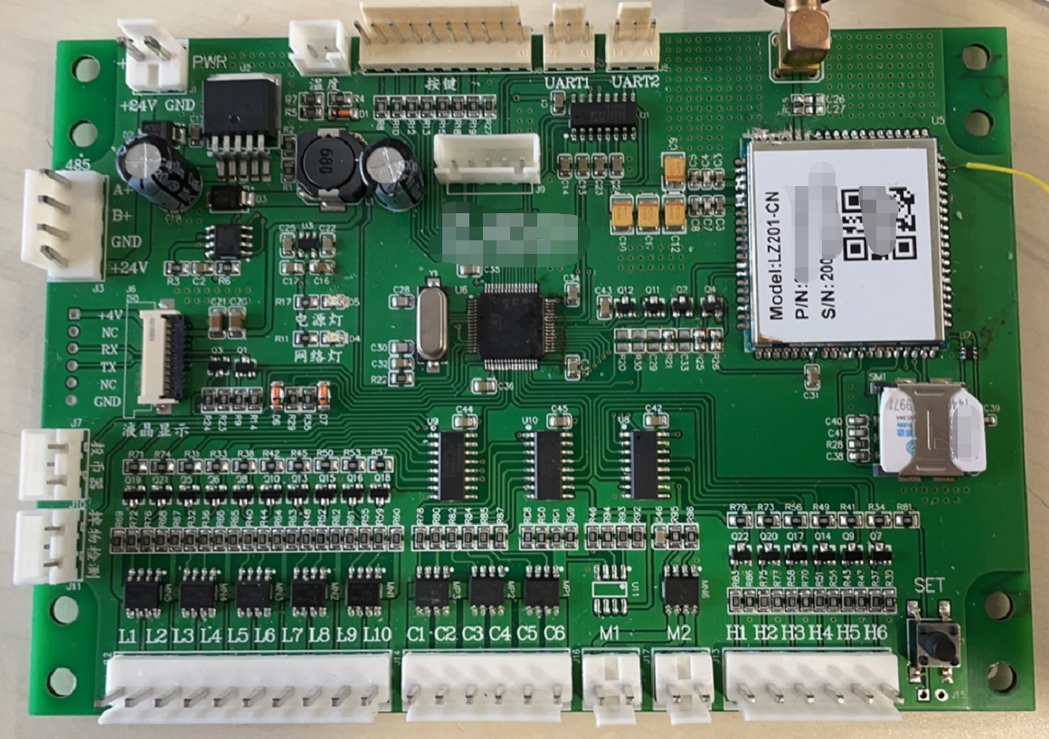
After you complete the hardware design, you can proceed with PCB layout, welding, and test. The following figure shows our finished PCB.
Step 2: Create a product on the Tuya IoT Platform
-
Log in to the Tuya IoT Platform, and click Create.
-
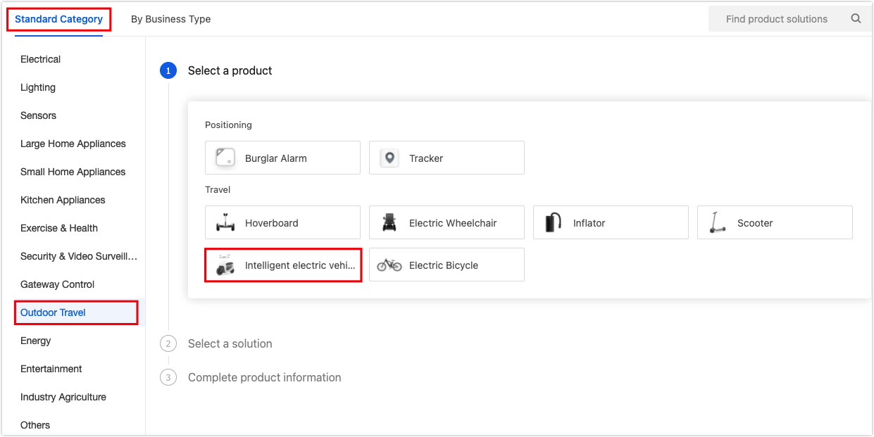
Find Standard Category, and click Outdoor Travel > Intelligent electric vehicle.
-
Click Intelligent electric vehicle on the Custom Solution tab.
-
Complete the basic information, select LTE Cat.1 as the protocol, and click Create.

-
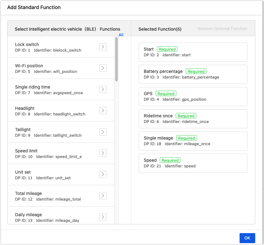
Add standard functions as needed.
-
(Optional) If you do not find the required functions, find Custom Functions and click + Add to create functions.
We create two functions: one is Item to get data from the cloud and the other is Inventory to send data to the cloud.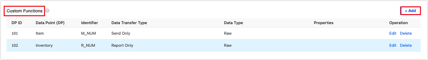
-
Click the Device Panel tab and select a panel. For convenient testing, you can select the debugging panel and change it later.
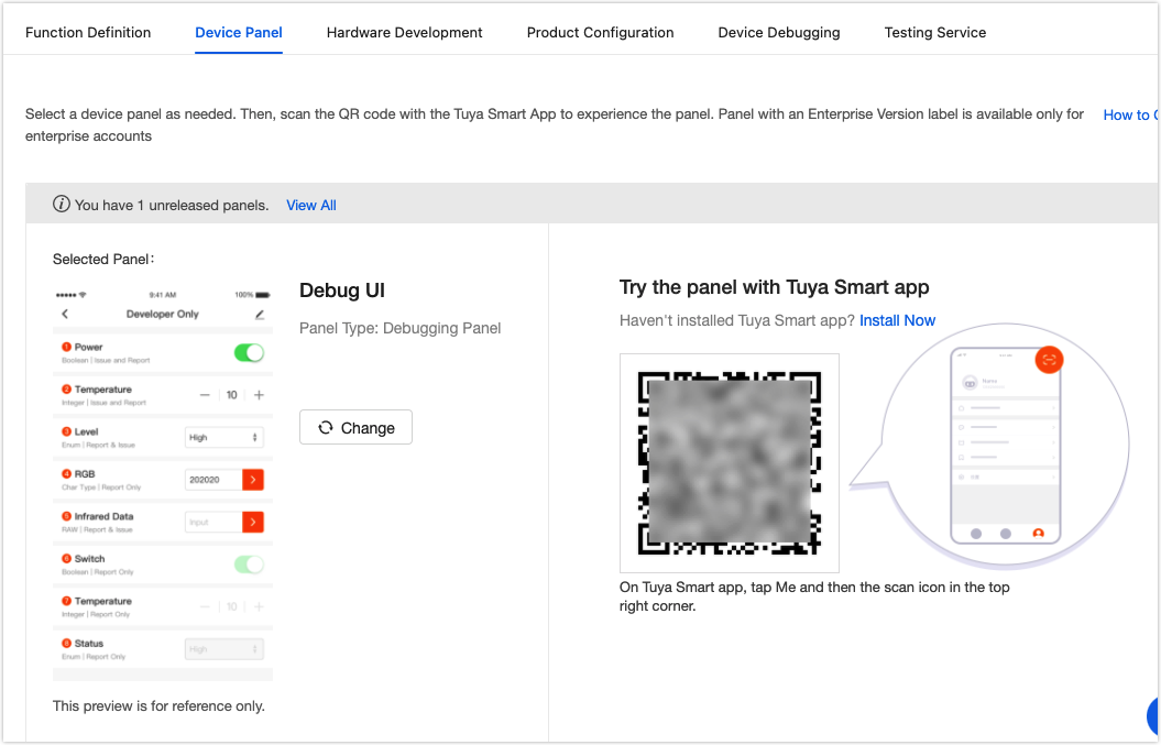
-
Click the Hardware Development tab. Select Tuya Standard Module MCU SDK and then LZ201-CN LTE Cat.1 Module.
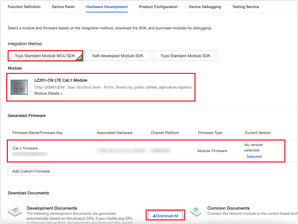
-
Scroll down the page and find Download Documents. Click Download All to get all the files for embedded programming.
-
Step 3: Embedded programming
Add the files in the SDK to your project and correct your code as per the error message.
You might use a different MCU, so the following driver is for your reference. For the full sample code, see tuya-iotos-embeded-mcu-demo-4g-vending-machine.
Configure serial port
 /***********************************************************
 *   Function:  USART3_Init
 *   Input:     uint32_t pclk2,uint32_t bound
 *   Output:    none
 *   Return:    none
 *   Notice:    USART initialization
 ***********************************************************/
void USART3_Init(uint32_t pclk2,uint32_t bound)
{
	float temp;
	uint16_t mantissa;
	uint16_t fraction;
	temp=(float)(pclk2*1000000)/(bound*16);// Get USARTDIV.
	mantissa=temp;  			    // Get the integer part.
	fraction=(temp-mantissa)*16; // Get the decimal part.
	mantissa<<=4;
	mantissa+=fraction;

	RCC->APB2ENR|=1<<3;   // Enable the clock for PORTB.
	RCC->APB1ENR|=1<<18;  // Enable the clock for USART3.
	GPIOB->CRH&=~(0xf<<8|0xf<<12);
	GPIOB->CRH|=0X0B<<8|8<<12;// // Configure GPIO state.
	GPIOB->ODR|=1<<11;

	RCC->APB1RSTR|=1<<18;   // Reset USART3.
	RCC->APB1RSTR&=~(1<<18);// Stop reset.
	// Set baud rate.
	USART3->BRR=mantissa; // Set baud rate.
	USART3->CR1|=0X200C;  // No parity, and 1 stop bit. 			USART3->CR1|=1<<8;    // Enable PE interrupt.
	USART3->CR1|=1<<5;    // Enable the RXNE interrupt.
	MY_NVIC_Init(1,2,USART3_IRQn,2);// Group 2
}
Receive serial data
 /***********************************************************
 *   Function:  USART3_IRQHandler
 *   Input:     none
 *   Output:    none
 *   Return:    none
 *   Notice:    USART interrupt handler function. Receive one byte of data in interrupt mode.
 ***********************************************************/
void USART3_IRQHandler(void)
{
	if(USART3->SR&(1<<5))// Received data.
	{
		uart_receive_input((unsigned char)(USART3->DR));
	}
}
Send serial data
 /***********************************************************
 *   Function:  Uart3_PutChar
 *   Input:     uint8_t
 *   Output:    none
 *   Return:    uint8_t
 *   Notice:    Send one byte of data to check whether a timeout has happened.
 ***********************************************************/
uint8_t Uart3_PutChar(uint8_t data)
{
	uint8_t ret=1;
	uint16_t timeout=0x8000;

	USART3->DR = data;
	while((USART3->SR&1<<6)! =1<<6)// Wait until the transmission is completed.
	{
		timeout--;
		if( 0 == timeout )
		{
			ret = 1;
			break;
		}
	}

	if( 0 != timeout )
	{
		ret = 0;
	}
	return ret;
}
/**
 * @brief  Send serial data
 * @param[in] {value}  The one byte of data to be sent by UART.
 * @return Null
 */
void uart_transmit_output(u8 value)
{
    //#error "Specify the UART transmission function and delete this line"
	Uart3_PutChar(value);
/*
    // Example:
    extern void Uart_PutChar(u8 value);
    Uart_PutChar(value);                                    // UART transmission function
*/
}
Read data through 74HC165 shift register
 /***********************************************************
 *   Function:  HC165In
 *   Input:     none
 *   Output:    none
 *   Return:    uint8_t
 *   Notice:    Read values of the eight pins of 74HC165 and return 8-bit data.
 ***********************************************************/
uint8_t HC165In(void)
{
	uint8_t i,dat=0;
	CP_SET;
	PL_RESET;
	delay_us(10);
	PL_SET;
	delay_us(10);
	for(i=0;i<8;i++)
	{
		dat=dat<<1;
		if(ODATA==1)
		{
			dat=dat+1;
		}
		CP_RESET;
		delay_us(10);
		CP_SET;
		delay_us(10);
	}
	CP_RESET;
	return dat;
}
Send data through 74HC595 shift register
This function is used to output a different level signal through 74HC595 to n-channel MOSFET and p-channel MOSFET. This way, we can control motor rotation.
 /***********************************************************
 *   Function:  HC595Send
 *   Input:     uint16_t
 *   Output:    none
 *   Return:    none
 *   Notice:    Output 16-bit data through pins of the two 74HC595 shift registers.
 ***********************************************************/
void HC595Send(uint16_t data)
{
    uint8_t j;
    LOCK_RESET;
    delay_us(10);
    for (j = 16; j > 0; j--)
    {
		SHIFT_RESET;
        delay_us(10);

        if(data & 0x8000)
        {
            INDATA_SET;
        }
        else
        {
            INDATA_RESET;
        }

        delay_us(10);
        data <<= 1;
        SHIFT_SET;
        delay_us(10);
    }
    LOCK_SET;
    delay_us(10);
}
For example, to rotate the Xth (0≤X≤9) motor for delivering a product, we can call
HC595Send(1<<X||1<<10);1<<Xindicates the high level signal is output to the Xth p-channel MOSFET.1<<10indicates the high level signal is output to n-channel MOSFET.Note: All the n-channel MOSFETs in the circuit use the same signal pin, so
1<<10is fixed.To stop motor rotation, we can call
HC595Send(0);Parameters of the function differ depending on circuit design. Adjust them based on your hardware.
Process commands from the cloud
The length of data from the cloud is 6 bytes. We can specify that bit 0 is the product tray number, bit 1 is the product number, and bit 2 to bit 5 is the order number.
You can specify the communication protocol as per your needs. The following program is for your reference.
/*****************************************************************************
Function name: dp_download_m_num_handle
Feature description: a processing function for DPID_M_NUM.
Input parameters: value indicates the data source
                : length: the length of the data
Return parameters: Return SUCCESS on success, and ERROR on failure
Instruction: For the send-only data point, the results must be sent to the cloud after the operation is completed.
*****************************************************************************/
static unsigned char dp_download_m_num_handle(const unsigned char value[], unsigned short length)
{
    // Example: This is a data point of raw type.
    unsigned char ret;
		const unsigned char error[6]={"ERROR1"};
    /*
    // Process data of raw type.

    */
		if((length==6)&&(value[0]<11)&&(value[1]<10))
		{
			IoT_receive[Q_U3.rear].data[0]=value[0];
			IoT_receive[Q_U3.rear].data[1]=value[1];
			IoT_receive[Q_U3.rear].data[2]=value[2];
			IoT_receive[Q_U3.rear].data[3]=value[3];
			IoT_receive[Q_U3.rear].data[4]=value[4];
			IoT_receive[Q_U3.rear].data[5]=value[5];
			F_TASK_MOTOR_OPEN++;
			rear_inc(&Q_U3);
		}
		else
		{
			mcu_dp_raw_update(DPID_R_NUM,error,6);
		}
    // Return the result of the operation.
    ret = mcu_dp_raw_update(DPID_M_NUM,value,length);
    if(ret == SUCCESS)
        return SUCCESS;
    else
        return ERROR;
}
Compile and download
After programming is completed, click Build and correct your code if any error occurs.
Then, download the program to the development board and test it.
STM32 supports debuggers like ST-Link and J-Link. ST-Link is recommended. The table below provides an overview of which pins to connect:
ST-Link STM32F103 SWCLK SWCLK SWDIO SWDIO NRST NRST VDD VDD GND GND After connecting ST-Link to your development board, click Download.
Step 4: Demonstration
Open the Tuya Smart app and tap the panel you selected for the vending machine. Find the created data point Item, and enter a value in the format of XXYYZZZZZZZZ for testing.
XXindicates the Xth product tray.YYindicates the remaining products on the tray.ZZZZZZZZindicates the order number. It can be any value.
For example, enter
0104aabbccdd, which indicates the first tray has four products now, and the order number isaabbccdd.After the data is sent, you will find the motor starts rotating and stops after the product falls.
Note: The inventory value must match the item. For example, if the first tray has four products, the valid value is
0104. Invalid values like0105and0103can not enable the motor to rotate.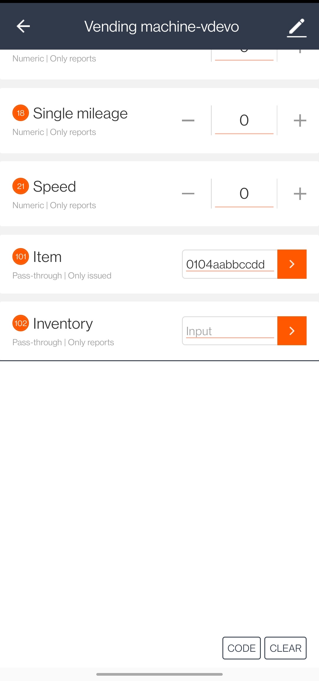
Summary
The Tuya IoT Platform provides convenient IoT development tools and services, which are designed to make your IoT project much easier and efficient. Check it out and discover more awesome ideas.
Is this page helpful?
YesSuggestions


