Prototype a Smart AC Controller

Overview
Smart AC controller is such a magic gadget that lets you use your traditional air conditioner in a smart way. It is actually a smart plug but is made for air conditioning and is more versatile.
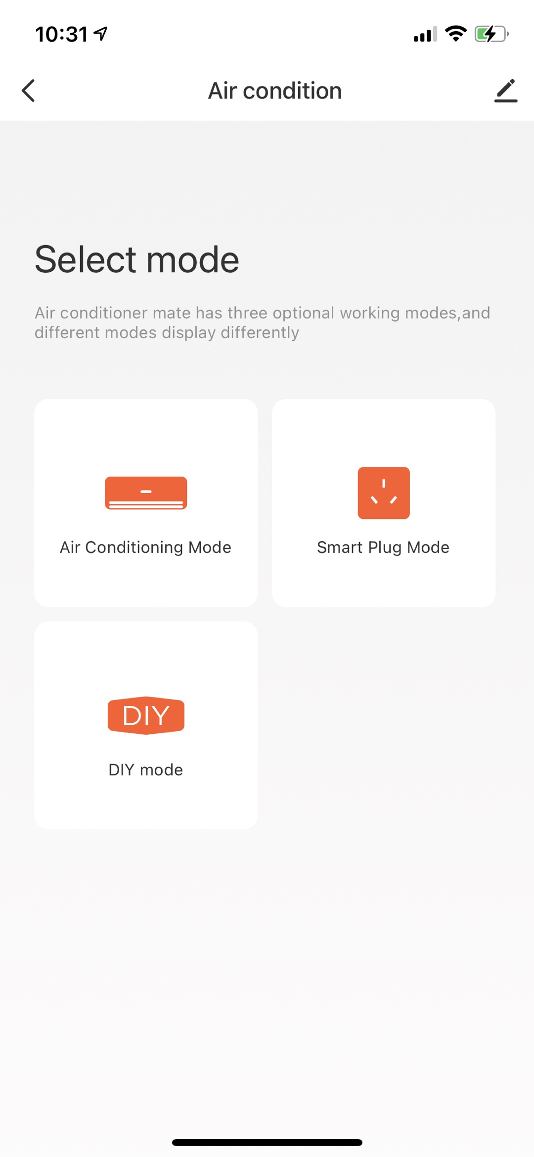
In this project, we will show you how to make a smart AC controller without coding, which can work in three modes, AC mode, plug mode, and DIY mode.
-
AC mode lets you ditch the remotes and control the AC and nightlight on/off with your mobile phone anywhere, anytime.
-
Plug mode is designed for easy control of a nightlight. It supports the countdown timer, scheduled task, and potentiometer-based brightness adjustment.
-
DIY mode allows the AC controller to mimic the infrared signal from your home appliances’ remotes. The end result is that you can control all your infrared devices with a mobile phone.
Materials
WR3E module
Count:1
Steps
Step 1: Circuit design
Design circuits based on the expected features.
Microcontroller circuit
We use Tuya’s WR3E low-power Wi-Fi module as the microcontroller unit.
This module consists of a highly integrated Wi-Fi chip RTL8710BN and external flash interface, with built-in Wi-Fi stacks and various library functions. It combines a low-energy ARM®Cortex™-M4 MCU, wireless MAC/baseband/RF, and 1T1R (1 transmitter/1 receiver) design. It provides output frequency up to 125 MHz, 256 KB embedded SRAM, 2 MB flash memory, and configurable GPIOs that can function as digital peripherals for various applications.
WR3E is a real-time operating system (RTOS), integrated with all wireless MAC and TCP/IP libraries. For more information, see WR3E Module Datasheet.
We supply 5V main power from the USB port. The module operates at 3.0V to 3.6V so we use a low-dropout (LDO) regulator or DC/DC buck converter to step down the voltage.
The schematic diagram is as follows.
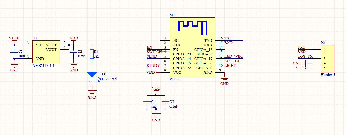
U1is the AMS1117-3.3 LDO voltage regulator. It steps down 5V USB power source to 3.3V to supply the WR3E module.D1is the power indicator. When the module is powered on,D1is on.TXDandRXDare used for serial data transmission.LOG_TXis used to print logs. The three I/O pins are broken out fromP2.
Infrared transmitter and receiver circuit
Most of our home appliances like air conditioners and TV are infrared-controlled so we design an infrared transmitter and receiver circuit.
The schematic diagram is as follows.
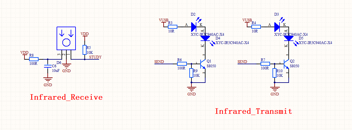
R5is a 10K pull-up resistor to enhance the immunity to EMI of theSTUDYpin.D6is an infrared remote receiver IRM-3638 from Everlight. IRM-3638 features a peak wavelength of 940 nm, a carrier frequency of 38 kHz, with excellent immunity to EMI. The demodulated output signal can directly be decoded by a microprocessor.D5,D4,D3, andD2are IR333-A IR LEDs, with a wavelength of 940 nm, 20 mA operating current, and 1.4V forward voltage. These diodes provide good consistency and resistance.
The four infrared LEDs transmit data in four directions to cover the broadest effective areas. You can prepare the infrared LED as needed.
Nightlight
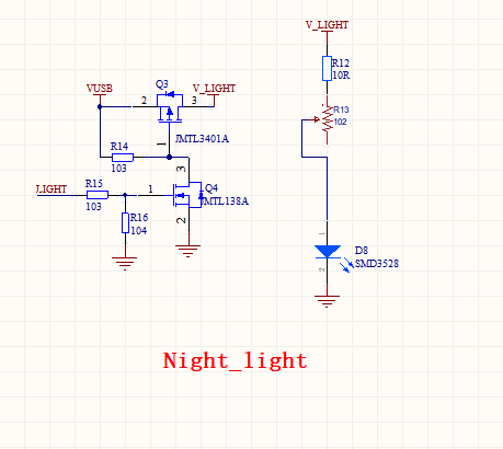
D8is a warm white SMD 3528 chip, with a maximum current of 30 mA. SMD 3528 can provide high brightness, a large emitting angle, low thermal resistance, high uniformity of the emitting color, low light decay, and a long life span.R13is a 1k ohm potentiometer, used to adjust the brightness of the warm white LED.Q3andQ4are two field-effect transistors. WhenLIGHToutputs high,Q3is on-state and the warm light LED is turned on. WhenLIGHToutputs low,Q3is cut-off and the warm light LED is turned off.
Wi-Fi status indicator
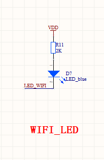
This indicator is used to tell you the current network connection. The indicator flickering slowly or quickly and the guide on the mobile app can help you complete device pairing.
When the infrared LED transmits data, this indicator will flicker to tell you data is sent.
Button
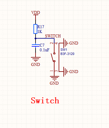
This button is used to initiate pairing. You can press and hold the button to let the AC controller enter pairing mode.
You can also press or release the button to turn on or off the nightlight.
The circuit design is completed. If you have any innovative ideas, add them to this project!
-
See the full schematic diagram.
-
See the full PCB.
Step 2: Structural design
Design an enclosure for the smart AC controller. The following is our 3D printing model for your reference.
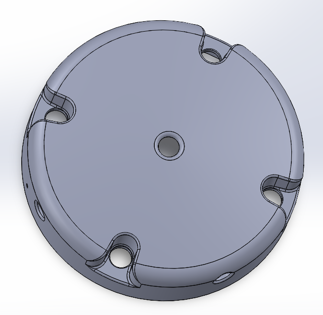
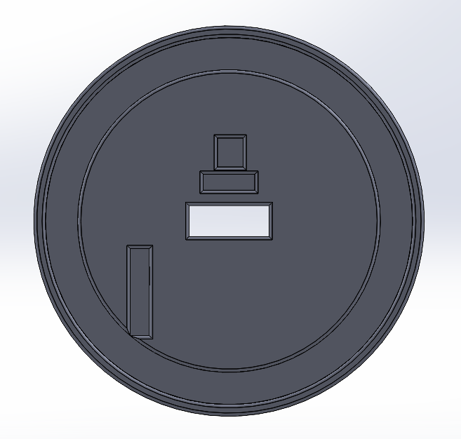
You can download the STL files of the top cover and bottom plate models.
Step 3: Operations on IoT Platform
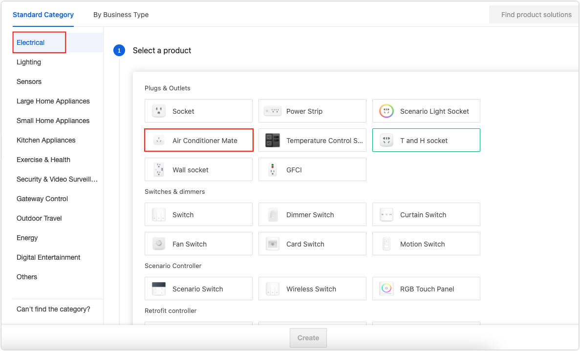
Creates a product
-
Log in to the Tuya IoT Platform.
-
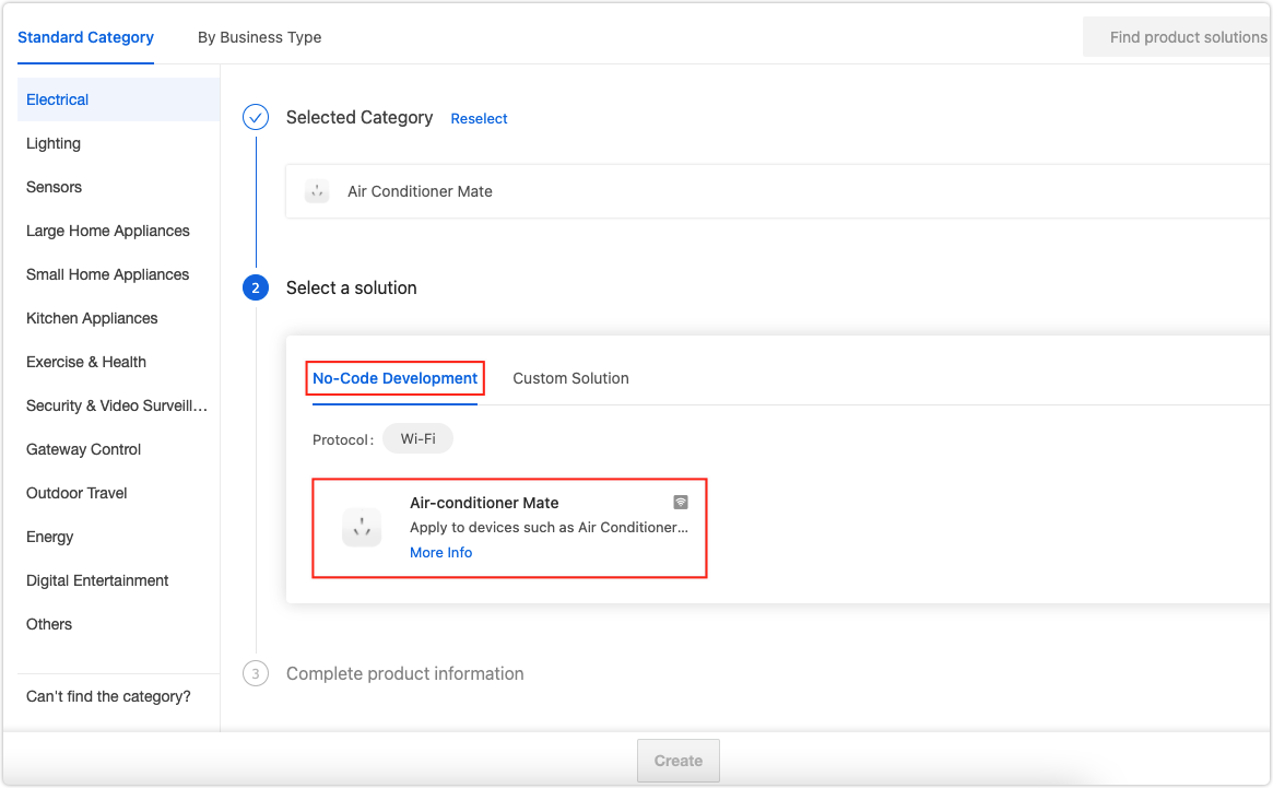
Select the Standard Category and then Electrical > Air Conditioner Mate.
-
Select the No-Code Development tab, complete the product details, and click Create.
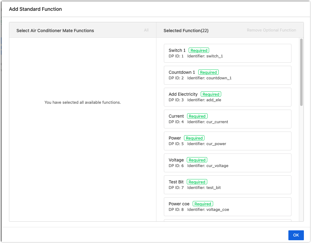
Function definition
Leave the default functions as they are and click OK.
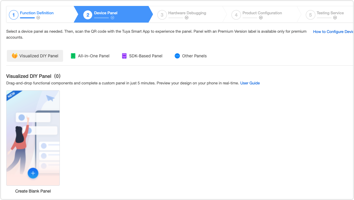
Device panel
Tuya provides a bunch of control panels, including the ready-made all-in-one panel, SDK-based panel, and visualized DIY panel that allows you to easily customize a panel by drag-and-drop.
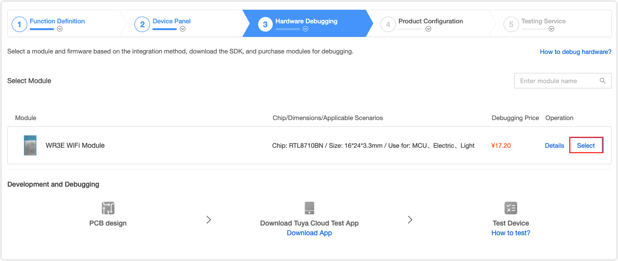
Hardware debugging
-
Select a network module and configure parameters based on the following table.
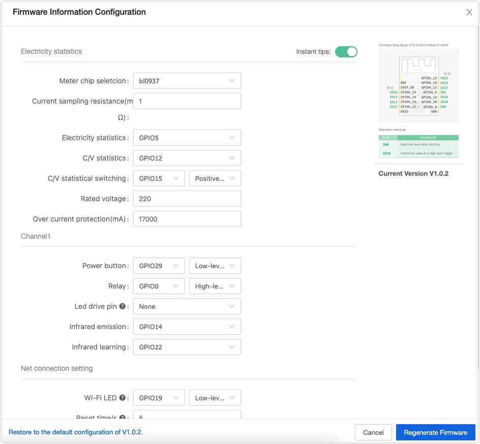
Parameter types Parameters Configuration Electricity statistics All parameters keep the defaults. Channel1 Power button Indicates the switchpin in the schematic diagram. Select GPIO29 and then Low-level active.Relay Indicates the nightlight. Select GPIO0 and then High-level drive. Infrared emission keep the defaults. Infrared learning keep the defaults. Net connection setting Wi-Fi LED Select GPIO19 and then Low-level active. Reset time/s Select the parameter as per your circuit design. Trigger mode of first distribution network Select the parameter as per your circuit design. Long press to network light flashing is recommended. Net indicator when connected Select the parameter as per your circuit design. Lighting is recommended. Note: You can specify the required I/Os for the above parameters. Make sure your configuration is consistent with your circuit design.
-
After all the parameters are set, click Generate Firmware.
-
Step 4: Firmware flashing
Generally, the module Tuya delivers to you is flashed with the firmware as per your configuration. If you choose to flash firmware by yourself, see the following instruction.
Request the technical support for the Cloud Module Burning Authorization Platform software, account and password, and license.
-
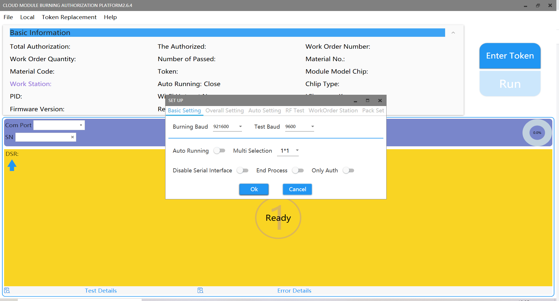
Open the software, click File > Setting.
-
In the dialog box that appeared, set the baud rate. We recommend you set the Burning Baud to 921600 and the Test Baud to 9600.
-
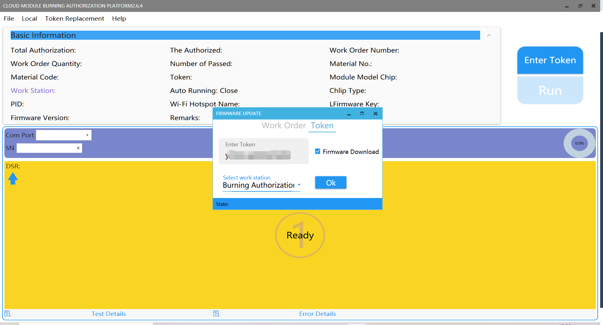
Click Enter Token and enter your license.
-
Check Firmware Download.
-
Select Burning Authorization in the Work Station field and click OK.
-
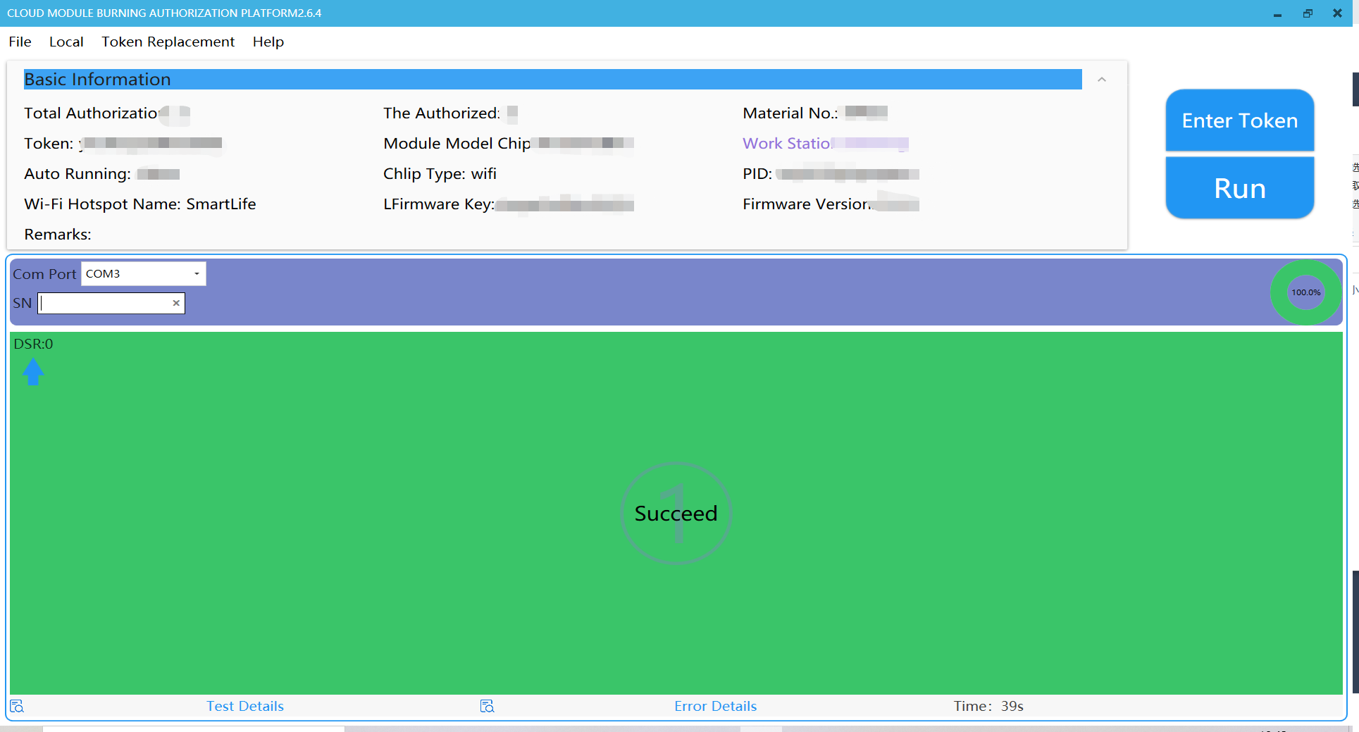
Click RUN. Do not disconnect your board from your PC while the flashing is in process.
-
When SUCCESS appears, it means firmware flashing is completed.
-
Step 5: Device pairing
-
Log in to the Tuya Smart or Smart Life app and tap the + icon in the top right corner.
-
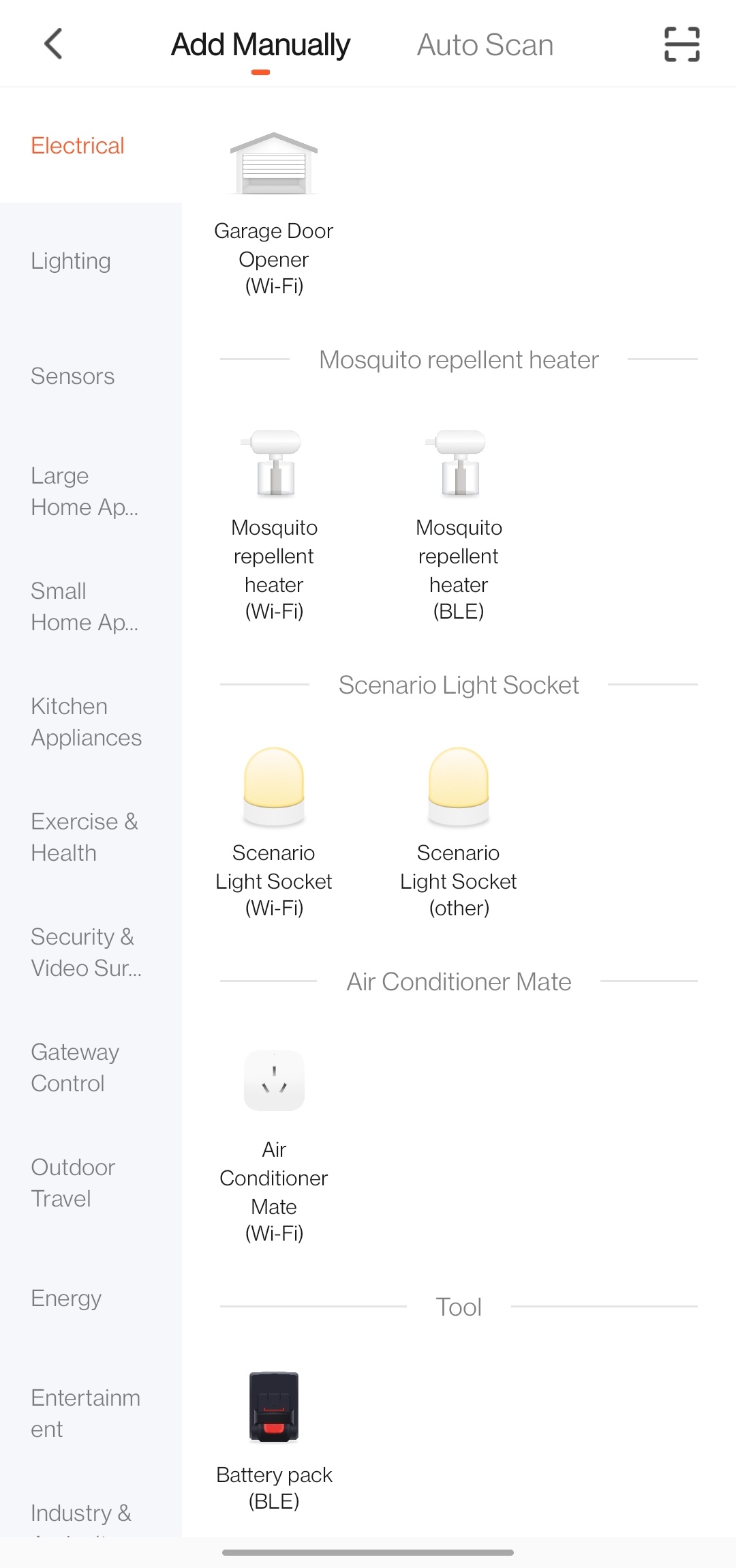
In Add Manually, tap Electrical category and find Air Conditioner Mate.
-
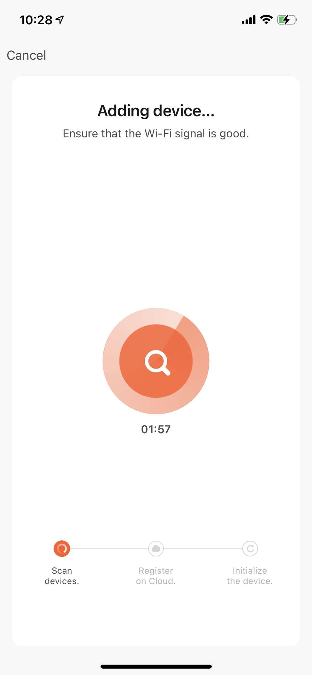
Enter the password of your 2.4 GHz Wi-Fi network and tap Next. Follow the instructions step by step to complete pairing.
-
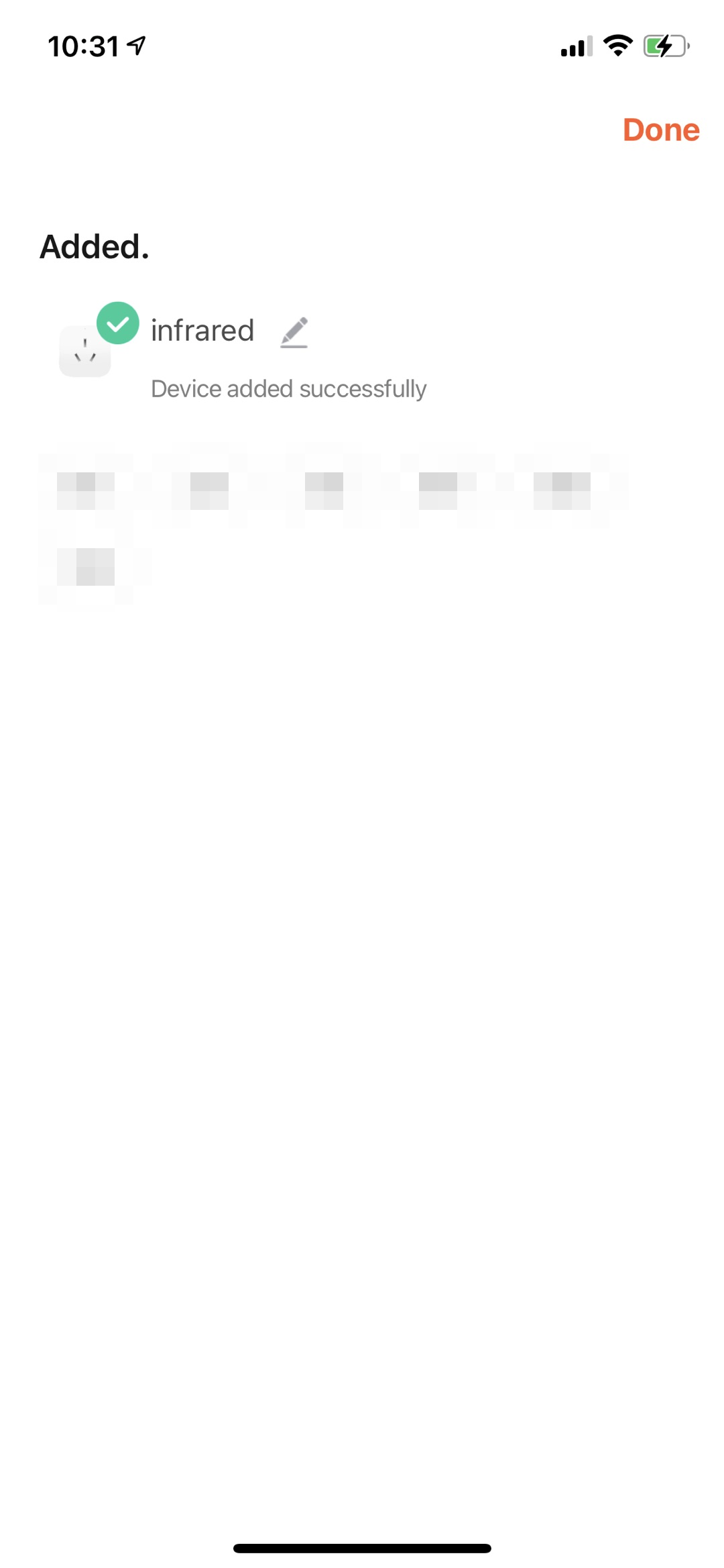
If everything works well, your device will be paired soon.
-
Summary
Congratulation! A smart AC controller is completed. Now, try controlling it with the mobile app and test each feature.
Is this page helpful?
YesSuggestions


