Prototype a Temperature and Humidity Sensor with Arduino
Overview
The temperature and humidity sensor is widely used in smart homes. The data of temperature and humidity collected by the sensor can be the trigger for executing home automation. With a preset scene linkage, when the temperature exceeds a threshold such as 29°C, the air conditioner (AC) will be automatically turned on to cool down the room. When the temperature is below a value such as 23°C, the AC will be off. AC automation can keep a preferred indoor temperature and help to conserve energy and cut down utility bills. Importantly, users can enjoy superior comfort all the way.
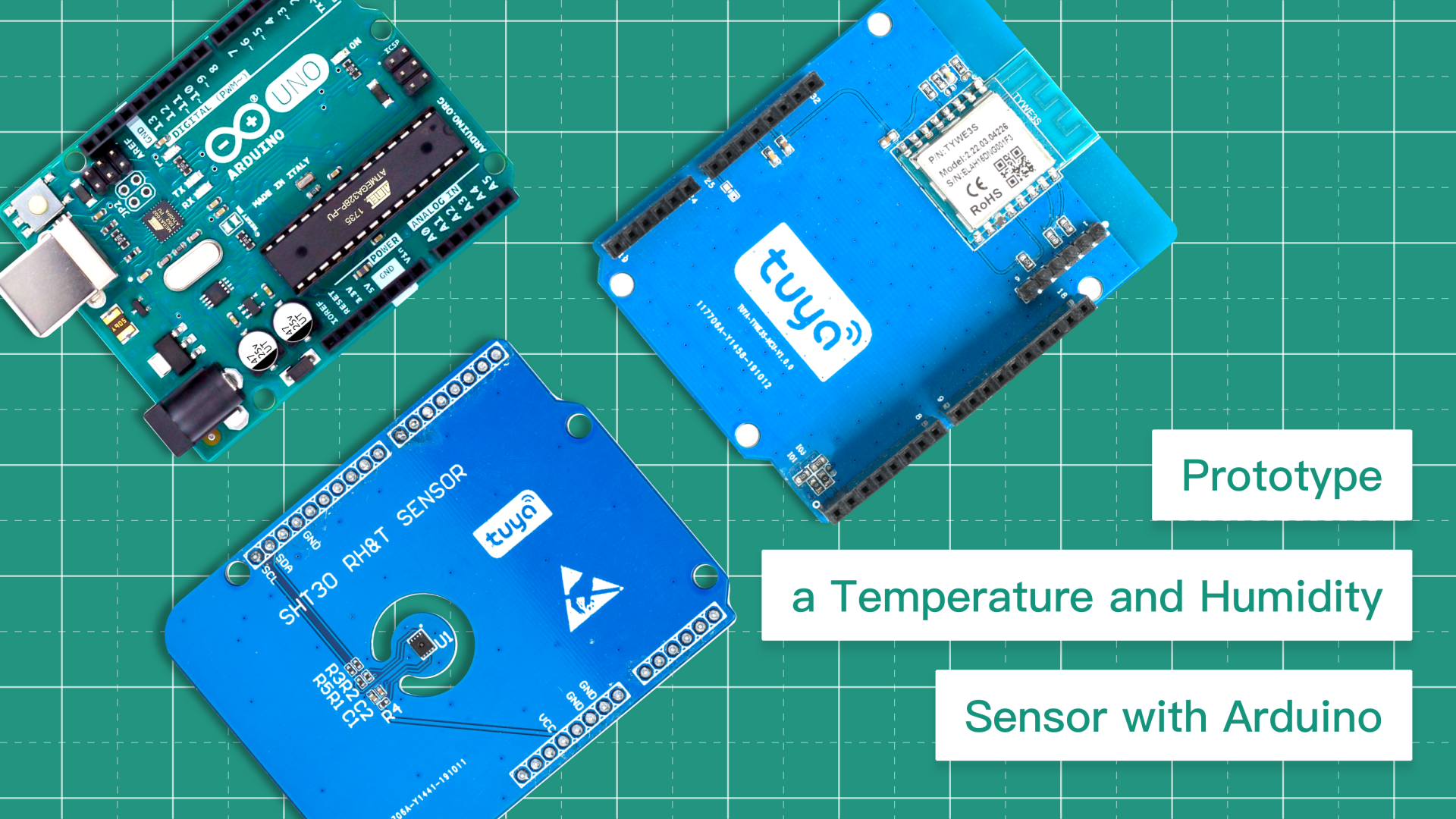
Based on the Tuya IoT Platform, you can prototype a smart temperature and humidity sensor from scratch with a few simple steps. In this project, we use an Arduino board, Tuya’s Wi-Fi communication board, and an SHT30 temperature and humidity sensor. SHT30 sensor collects data every one second and feeds the data to the Arduino board through I2C communication. The Arduino board communicates with Tuya’s Wi-Fi board using the UART. This way, we can pair the SHT30 sensor with the Tuya Smart app and then view the collected data and set device linkage on the mobile phone.
We use the Arduino IDE to compile and upload code, which is more friendly to projects with Arduino boards.
Materials
Steps
Step 1: Hardware connection
We use three boards to make this prototype.
- Temperature and humidity sensor board. The on-board SHT30 sensor with an I2C interface is used to collect and transmit data of temperature and humidity.
- Wi-Fi communication board. The on-board Tuya general Wi-Fi module is used to connect a device to the Tuya IoT Cloud. It has been flashed with the general firmware that includes the protocol for connecting Tuya’s module to Arduino Uno. This enables device control with a mobile app.
- MCU board. Arduino Uno can receive data and control data communication.
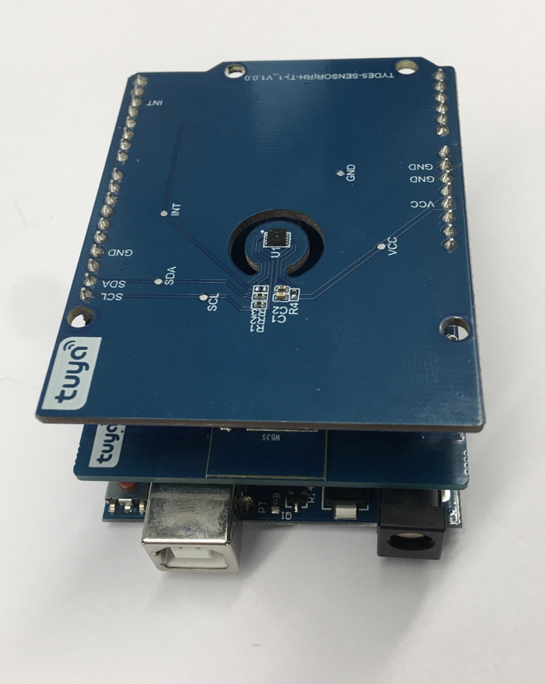
Connect the functional board, Wi-Fi communication board, and Arduino Uno together, as shown below.
Step 2: Arduino library installation
Set up IDE
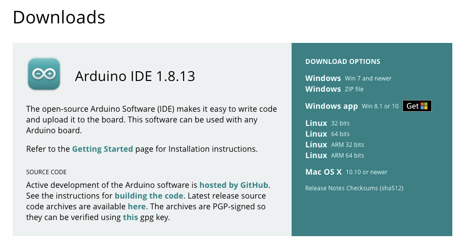
Download Arduino IDE. For more information, see Getting Started with Arduino products.
Install
Tuya_WiFi_MCU_SDKlibraryTwo approaches available:
- Open Arduino IDE and click the Sketch menu and then Include Library > Manage Libraries. Find
Tuya_WiFi_MCU_SDKand install. - Download the Tuya_WiFi_MCU_SDK library package. Unzip it and copy all of these files to the libraries folder inside your sketchbook. To find the location of your sketchbook folder, go to the top menu in Arduino IDE:
Windows: File > Preferences.
macOS: Arduino > Preferences.
Restart Arduino IDE and verify that
Tuya_WiFi_MCU_SDKappears in the Sketch > Include Library > Contributed libraries.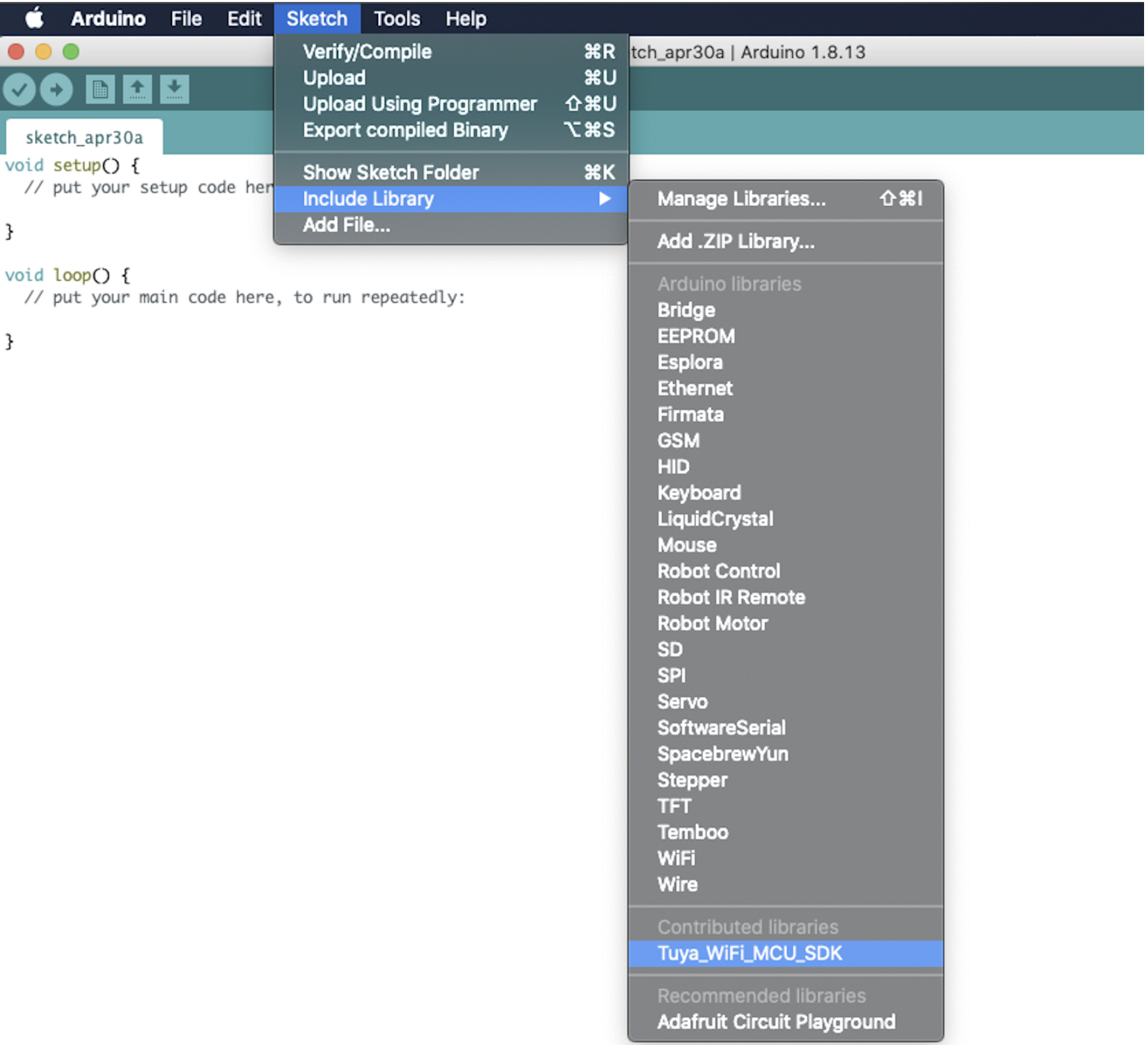
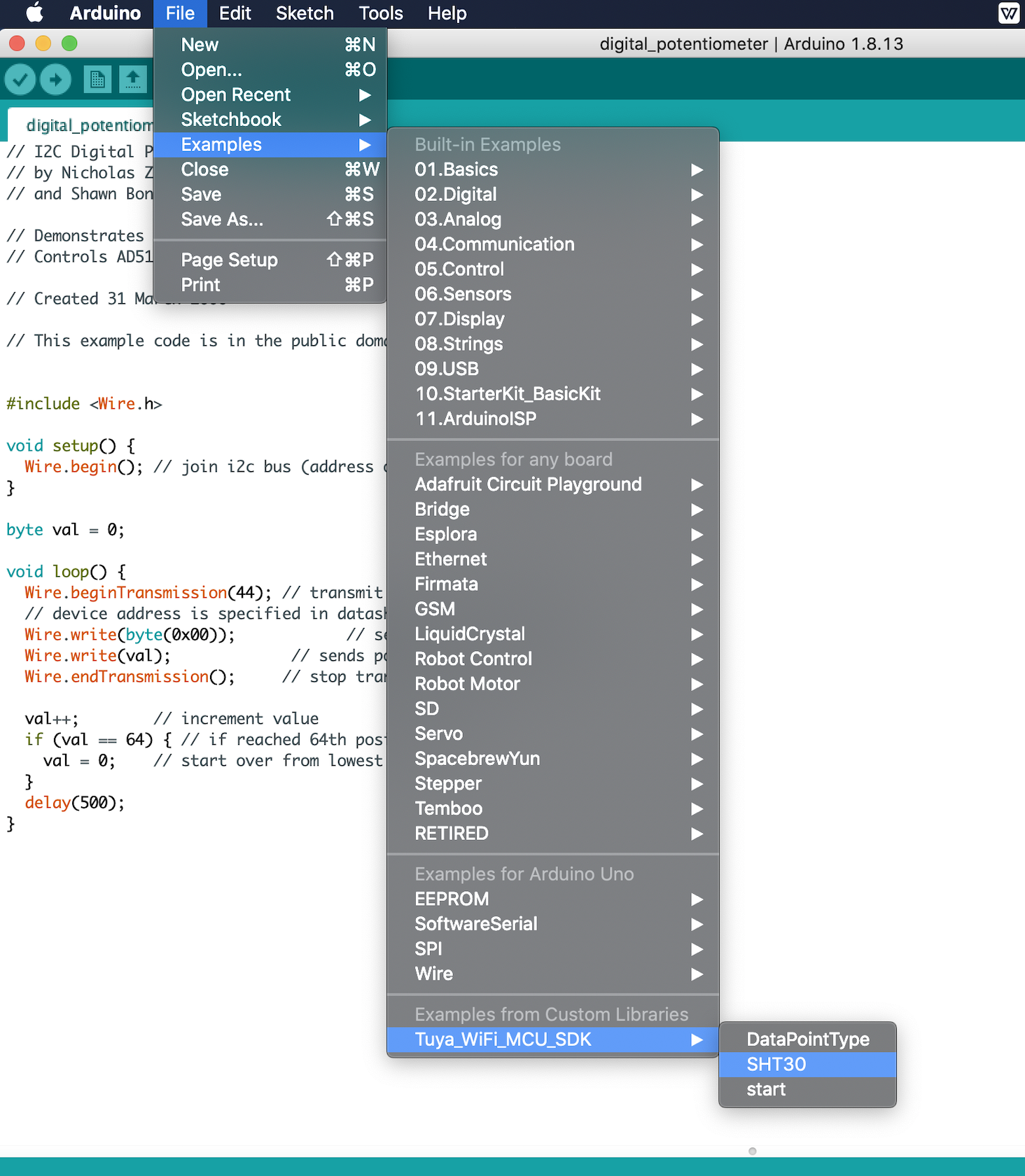
Select an example
Click the File menu > Examples > Tuya_WiFi_MCU_SDK. Select SHT30.
- Open Arduino IDE and click the Sketch menu and then Include Library > Manage Libraries. Find
Step 3: Example description
In this section, we will describe how the example SHT30 is implemented. For more information, see Arduino Development Guide.
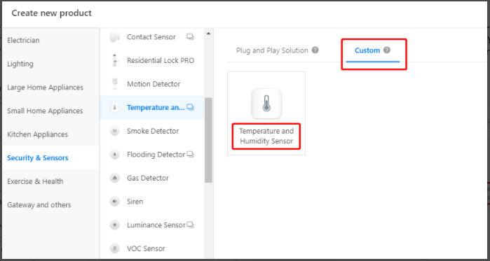
Create a product
- We need to create a temperature and humidity sensor on the Tuya IoT Platform to get the required product ID (PID) and data point (DP).
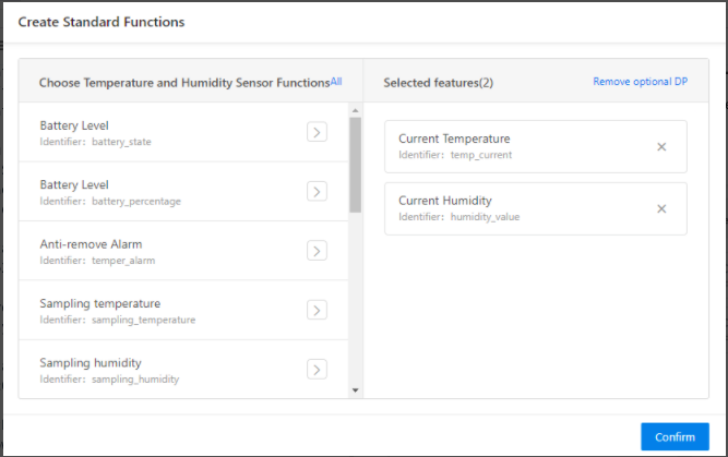
- Add two standard functions Current Temperature and Current Humidity.
Implementation of code
The code implements three features, namely pairing, device initialization, and data collection.
Pairing
Before uploading code to the Arduino board, you need to disconnect Tuya’s board from the Arduino board. The connection between these two boards might interfere with the uploading.
After successful uploading, you need to connect the Pins 0 and 1 on the Arduino board to theRXDandTXDon Tuya’s Wi-Fi board. Connect a jumper to Pin 7 and GND on the Arduino board to pull down for one second. Then, the module will enter pairing mode, and you can use the Tuya Smart app to pair with it. In the pairing process, the LED on the Arduino board will flicker. After the module is paired, the LED will stop flickering. Now, you can control the sensor with the app.Note: The default RX and TX pins are occupied by Tuya’s Wi-Fi board. You must leave it as is to avoid any unnecessary complications.
/* Current LED status */
unsigned char led_state = 0;
/* Connect network button pin */
int wifi_key_pin = 7;
/* last time */
unsigned long last_time = 0;

void setup()
{
    ...
   /* Initialize peripherals */
  // Initialize LED port and turn off LED.
  pinMode(LED_BUILTIN, OUTPUT);
  digitalWrite(LED_BUILTIN, LOW);
  // Initialize networking keys.
  pinMode(wifi_key_pin, INPUT_PULLUP);
    ...
  last_time = millis();
}

void loop()
{
    ...
  // Enter the pairing mode when Pin 7 is pressed.
  if (digitalRead(wifi_key_pin) == LOW) {
    delay(80);
    if (digitalRead(wifi_key_pin) == LOW) {
      my_device.mcu_set_wifi_mode(SMART_CONFIG);
    }
  }
  /* LED blinks when network is being connected */
  if ((my_device.mcu_get_wifi_work_state() ! = WIFI_LOW_POWER) && (my_device.mcu_get_wifi_work_state() ! = WIFI_CONN_CLOUD) && (my_device.mcu_get_wifi_work_state() ! = WIFI_SATE_UNKNOW)) {
    if (millis()- last_time >= 500) {
      last_time = millis();

      if (led_state == LOW) {
        led_state = HIGH;
      } else {
        led_state = LOW;
      }

      digitalWrite(LED_BUILTIN, led_state);
    }
      ...
}
Device initialization
#include <TuyaWifi.h>

TuyaWifi my_device;

/* Data point define */
#define DPID_TEMP_CURRENT     1
#define DPID_HUMIDITY_CURRENT 2

/* Current device DP values */
int temperature = 0;
int humidity = 0;

/* Stores all DPs and their types. PS: array[][0]:dpid, array[][1]:dp type.
 *                                     dp type(TuyaDefs.h) : DP_TYPE_RAW, DP_TYPE_BOOL, DP_TYPE_VALUE, DP_TYPE_STRING, DP_TYPE_ENUM, DP_TYPE_BITMAP
*/
unsigned char dp_array[][2] =
{
  {DPID_TEMP_CURRENT, DP_TYPE_VALUE},
  {DPID_HUMIDITY_CURRENT, DP_TYPE_VALUE},
};

unsigned char pid[] = {"xxxxxxxxxxxxxxxx"};// xxxxxxxxxxxxxxxx should be your product ID (PID).
unsigned char mcu_ver[] = {"1.0.0"};

void setup()
{
  Serial.begin(9600);
    ...
  my_device.init(pid, mcu_ver);
  // Incoming all DPs and their type arrays and DP numbers.
  my_device.set_dp_cmd_total(dp_array, 2);
  // Register callback function of downloading DP.
  my_device.dp_process_func_register(dp_process);
  // Register callback function of uploading all DPs.
  my_device.dp_update_all_func_register(dp_update_all);
    ...
}

void loop()
{
  my_device.uart_service();
    ...
  delay(1000);
}

/**
 * @description: DP download callback function.
 * @param {unsigned char} dpid
 * @param {const unsigned char} value
 * @param {unsigned short} length
 * @return {unsigned char}
 */
unsigned char dp_process(unsigned char dpid,const unsigned char value[], unsigned short length)
{
  /* All DPs can only be reported to the cloud */
  return SUCCESS;
}

/**
 * @description: Upload all DP status of the current device.
 * @param {*}
 * @return {*}
 */
void dp_update_all(void)
{
  my_device.mcu_dp_update(DPID_TEMP_CURRENT, temperature, 1);
  my_device.mcu_dp_update(DPID_HUMIDITY_CURRENT, humidity, 1);
}
Data collection
#include <Wire.h> /* SHT30 */ #define SHT30_I2C_ADDR 0x44 /* Current device DP values */ int temperature = 0; int humidity = 0; void setup() { ... // Initialize I2C communication as MASTER Wire.begin(); ... } void loop() { ... /* Get the temperature and humidity */ get_sht30_value(&temperature, &humidity); if ((my_device.mcu_get_wifi_work_state() == WIFI_CONNECTED) || (my_device.mcu_get_wifi_work_state() == WIFI_CONN_CLOUD)) { my_device.mcu_dp_update(DPID_TEMP_CURRENT, temperature, 1); my_device.mcu_dp_update(DPID_HUMIDITY_CURRENT, humidity, 1); } delay(1000); } void get_sht30_value(int *temp_value, int *humi_value) { unsigned char i2c_data[6]; // Start I2C transmission Wire.beginTransmission(SHT30_I2C_ADDR); // Send measurement command Wire.write(0x2C); Wire.write(0x06); // Stop I2C transmission Wire.endTransmission(); delay(500); // Request 6 bytes of data Wire.requestFrom(SHT30_I2C_ADDR, 6); // Read 6 bytes of I2C data // Temperature MSB, temperature LSB, temperature CRC, humidity MSB, humidity LSB, and humidity CRC if (Wire.available() == 6) { for (int i = 0; i < 6 ; i++) { i2c_data[i] = Wire.read(); } if ((sht30_crc(i2c_data, 2) == i2c_data[2]) && (sht30_crc(i2c_data+3, 2) == i2c_data[5])) {/* crc success */ *temp_value = (((((i2c_data[0] * 256.0) + i2c_data[1]) * 175) / 65535.0) - 45) * 100; *humi_value = ((((i2c_data[3] * 256.0) + i2c_data[4]) * 100) / 65535.0) * 100; } else { *temp_value = 0; *humi_value = 0; } } } /** * @description: Check SHT30 temperature and humidity data * @param {unsigned char} *data * @param {unsigned int} count * @return {*} */ unsigned char sht30_crc(unsigned char *data, unsigned int count) { unsigned char crc = 0xff; unsigned char current_byte; unsigned char crc_bit; /* Calculates 8-Bit checksum with given polynomial */ for (current_byte = 0; current_byte < count; ++current_byte) { crc ^= (data[current_byte]); for (crc_bit = 8; crc_bit > 0; --crc_bit) { if (crc & 0x80) crc = (crc << 1) ^ 0x31; else crc = (crc << 1); } } return crc; }- We need to create a temperature and humidity sensor on the Tuya IoT Platform to get the required product ID (PID) and data point (DP).
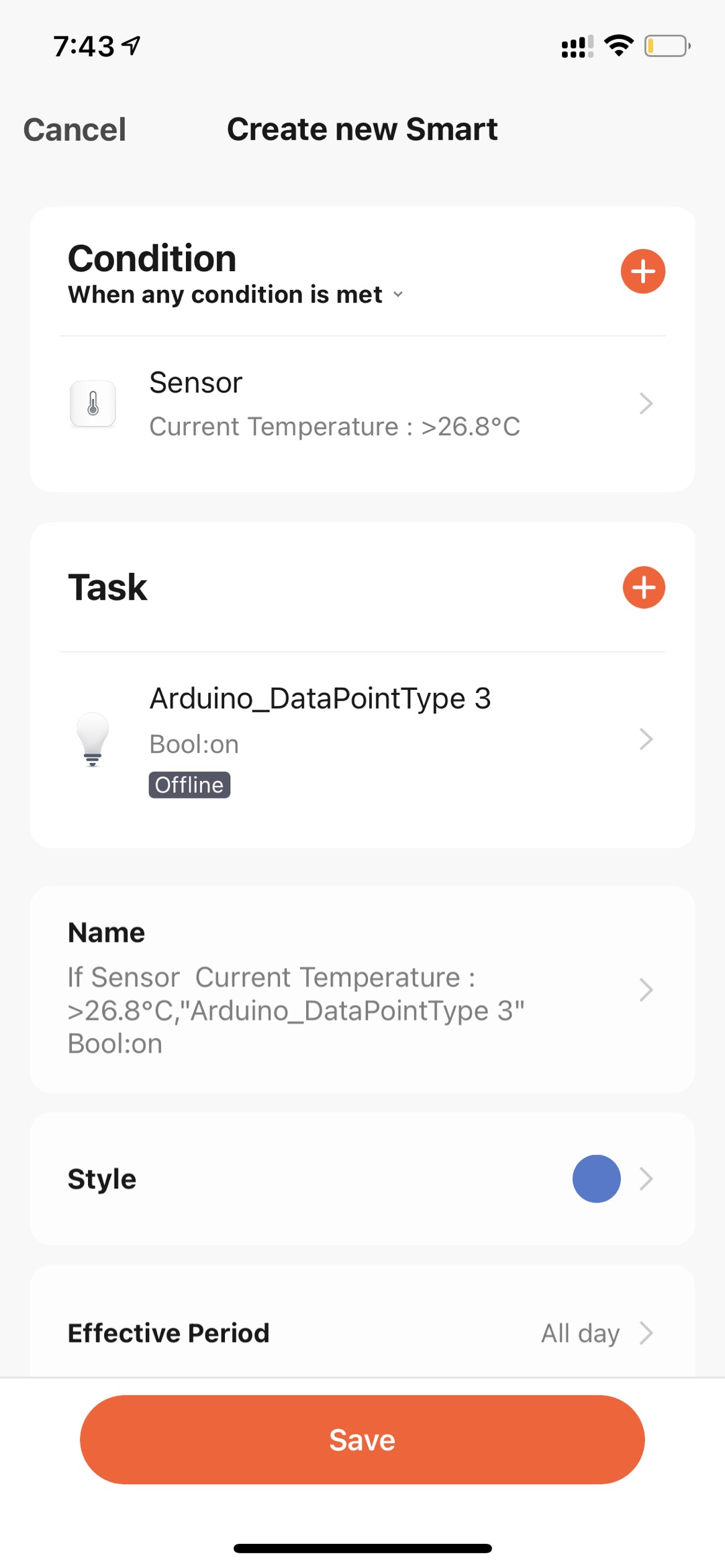
Step 4: Pairing and scene linkage
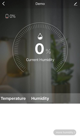
After uploading, connect a jumper to Pin 7 and GND on the Arduino board to pull down. The board will send a pairing command to Tuya’s module. When the LED starts to flicker, the module enters the pairing mode. Now, use the Tuya Smart app to pair with the module and test the data communication with the cloud.
A sensor can act as a ‘trigger’ in scene linkages. If you have ‘Powered by Tuya’ devices, you can set some interesting linkage with the Tuya Smart app. For more information, see Configure Scene Linkage.
Summary
Tuya IoT Platform provides convenient IoT development tools and services, which are designed to make your IoT project much easier and efficient. Check it out and discover more awesome ideas.
Is this page helpful?
YesSuggestions


