Prototype a Tuya IoT Connected DC Inverter Fan

Overview
As a perfect complement to an air conditioner, the smart fan is packed with useful and convenient features, like remote control, adjustable wind modes and speed levels, low noise and energy efficiency, and many more. This smart partner can give us an incredible experience in summer and winter.
In this tutorial, we will show you how to retrofit a DC inverter fan step-by-step and make it smart and connected. You will go through the steps of hardware design, feature implementation, and embedded programming.
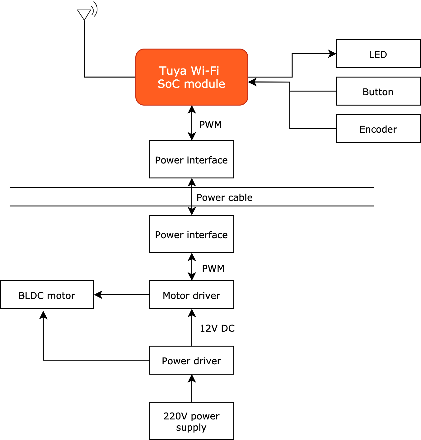
How it works
Materials
Brushless DC electric motor (BLDC)
Count:1The advantages of BLDC motors over AC motors are good speed–torque in moderate- to low-speed applications, high efficiency, and long lifetime. We use a three-phase 12V BLDC motor speed controller from Minebea.
Motor driver
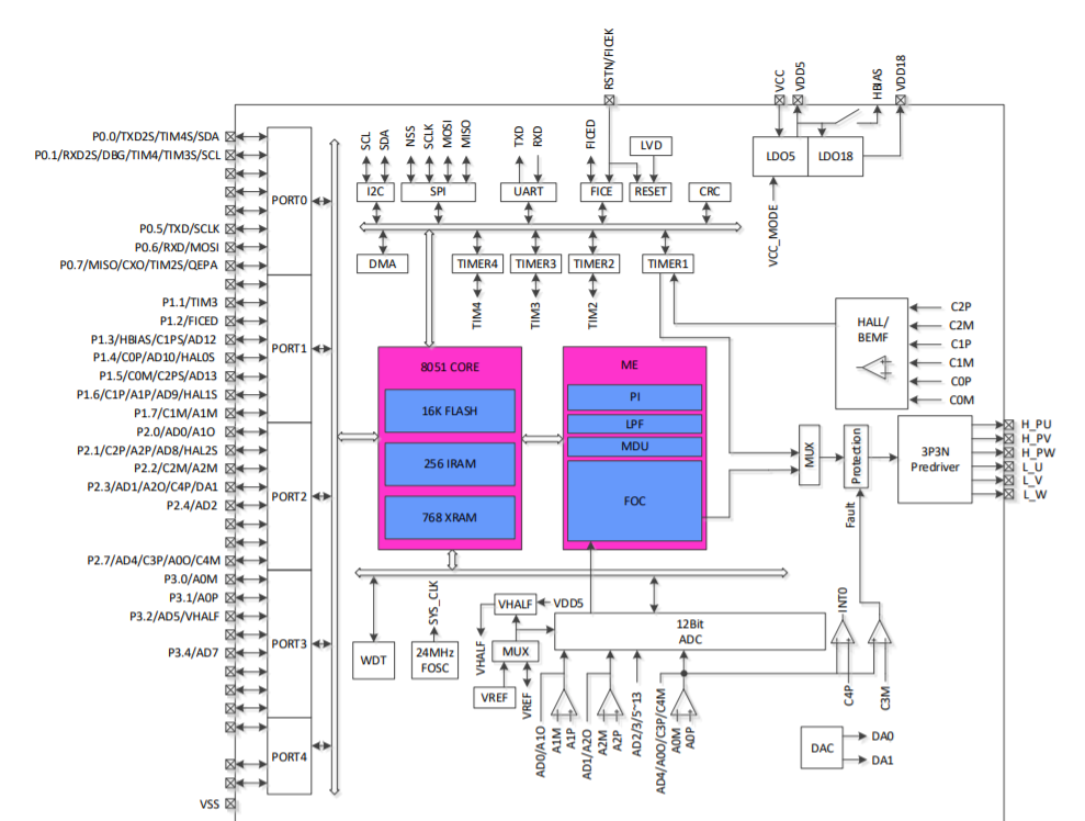
Count:1It is used to drive the BLDC motor. The FU6832 series chip from Fortior Technology is used as the BLDC microcontroller (MCU). Having a dual-core processor of 8051 core and motor control engine, the FU6832 series features 16 KB flash, 256 bytes internal RAM (IRAM), 768 bytes external RAM (XRAM), SSOP24 packaging, and integrated BLDC control algorithms.
Tuya's CBU Wi-Fi module
Count:1The module determines the wireless communication protocol of hardware. Wi-Fi is a common wireless technology utilized in residential and business scenarios. We use Tuya's CBU Wi-Fi network module.
Rotary encoder
Count:1It is used to set the fan speed. Increase the speed by clockwise rotation and decrease the speed by counterclockwise rotation. The shaft has unlimited 360-degree rotation. You can set the required speed levels as needed.
LED indicator
Count:8Prepare at least eight LEDs, whose status is controlled by the I/O output of the Wi-Fi module.
Button
Count:4It is used for on/off control, timer, network reset, and wind mode setting.
Power plug
Count:1Provide 12V DC 2A power for the fan.
Buck converter
Count:1Integrated with an SY8121B step-down chip from Silergy, it steps down the mains voltage to provide power for the Wi-Fi module and its peripherals, as well as the FU6832S motor driver chip and its peripherals.
Steps
1. Component design
The selection of components like the BLDC motor and motor driver is described in the section Materials above. In this section, you will get to know how these components work.
-
The I/O pin configuration on the motor driver chip:
-
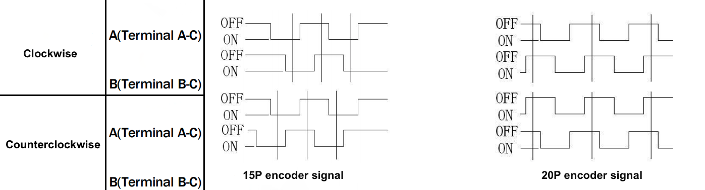
Rotary encoder (for setting fan speed):
-
Output signals of the encoder:
-
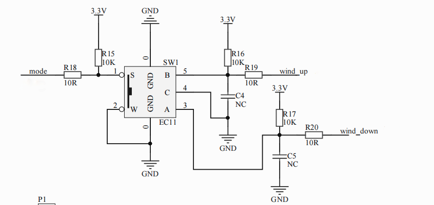
Peripheral circuit of the encoder:
-
-
Buttons: Four active-low buttons are used for the following functions:
-
Power switch: Turn on or off the fan.
-
Timer: Schedule the on/off time.
-
Wi-Fi reset: Clear the Wi-Fi connection and reset the network to factory defaults.
-
Fan mode: Switch the fan mode. Use the encoder to set the mode button.

-
-
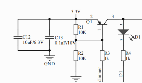
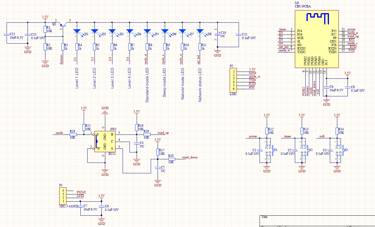
LEDs: LED status is controlled by the I/O output of the Wi-Fi module. LEDs are ON when output is low.
-
Four LEDs for speed levels.
-
Three LEDs for fan modes.
-
One LED for network status.
-
You can set an I/O pin to adjust LED light brightness as needed.
-
-
Signals: PWM signal is used for the signal transmission between the Wi-Fi module and the motor driver chip.
-
Power: A power plug connected to the mains provides 12V DC 2A power for the fan.
-
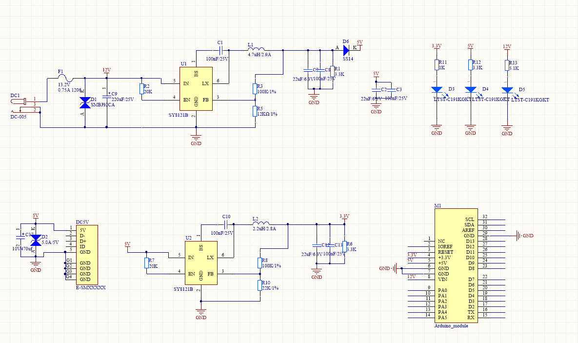
Buck converter: One 12V to 3.3V DC-DC buck converter steps down the mains voltage to provide power for the Wi-Fi module and its peripherals. One 12V to 5V DC-DC buck converter provides power for the FU6832S motor driver chip and its peripherals.
The synchronous step-down chip SY8121B from Silergy supports the high efficiency and fast response of the buck converter.
- Input voltage: 4.5V to 18V
- Output current: 2A (max)
2. Circuit design
-
Wi-Fi module and peripheral circuit:
-
DC-DC buck converter:
-
FU6832S motor driver chip and peripheral circuit:
3. Device features
| Feature | Description |
|---|---|
| Fan mode | Standard wind: Deliver constant airflow. Natural wind: Mimic natural wind by changing the fan speed in a random pattern with a 15-second interval. Sleep wind: The fan speed steps down automatically one level every one hour until it reaches the lowest speed. |
| Speed control | Rotate the encoder shaft to adjust the fan speed. Increase the speed by clockwise rotation (+) and decrease the speed by counterclockwise rotation (-). |
| Change mode | Press the encoder to change modes. Press and hold it to reset the fan. |
| Local timer | The fan will be automatically shut down when a timer is up. Each time the button is pressed, the timer function changes in the following order: timer off -> 1h -> 2h -> 3h -> 4h -> timer off. |
| LEDs for fan speed | Four LEDs display 8-level fan speed. Flickering LED indicates one-level adjustment. Steady-on LED indicates two-level adjustment. These four LEDs are also used for the local timer. |
| LEDs for Wi-Fi status and fan mode | Regarding the other four LEDs, one of them indicates Wi-Fi status and the rest buttons indicate fan mode. |
| Power | The power switch is used to turn on or off the fan. |
| Device pairing | Press and hold the Wi-Fi status button to enable pairing mode. |
| LED light adjustment | Adjust LED light brightness with the app. |
| Power-off memory | In case of power failure, the fan will resume its previous status after power-on. |
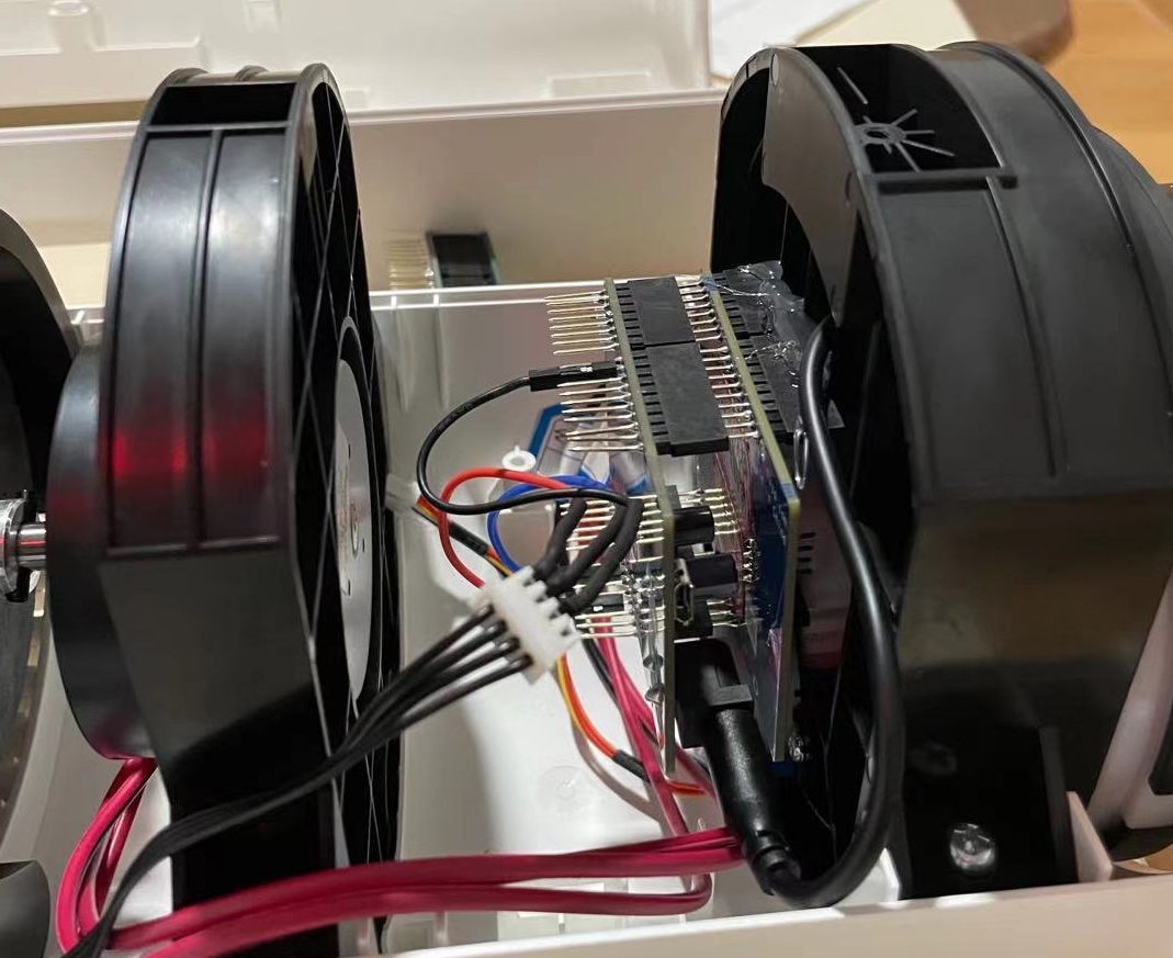
4: Component assembly
-
Motor driver board and buck converter board:
-
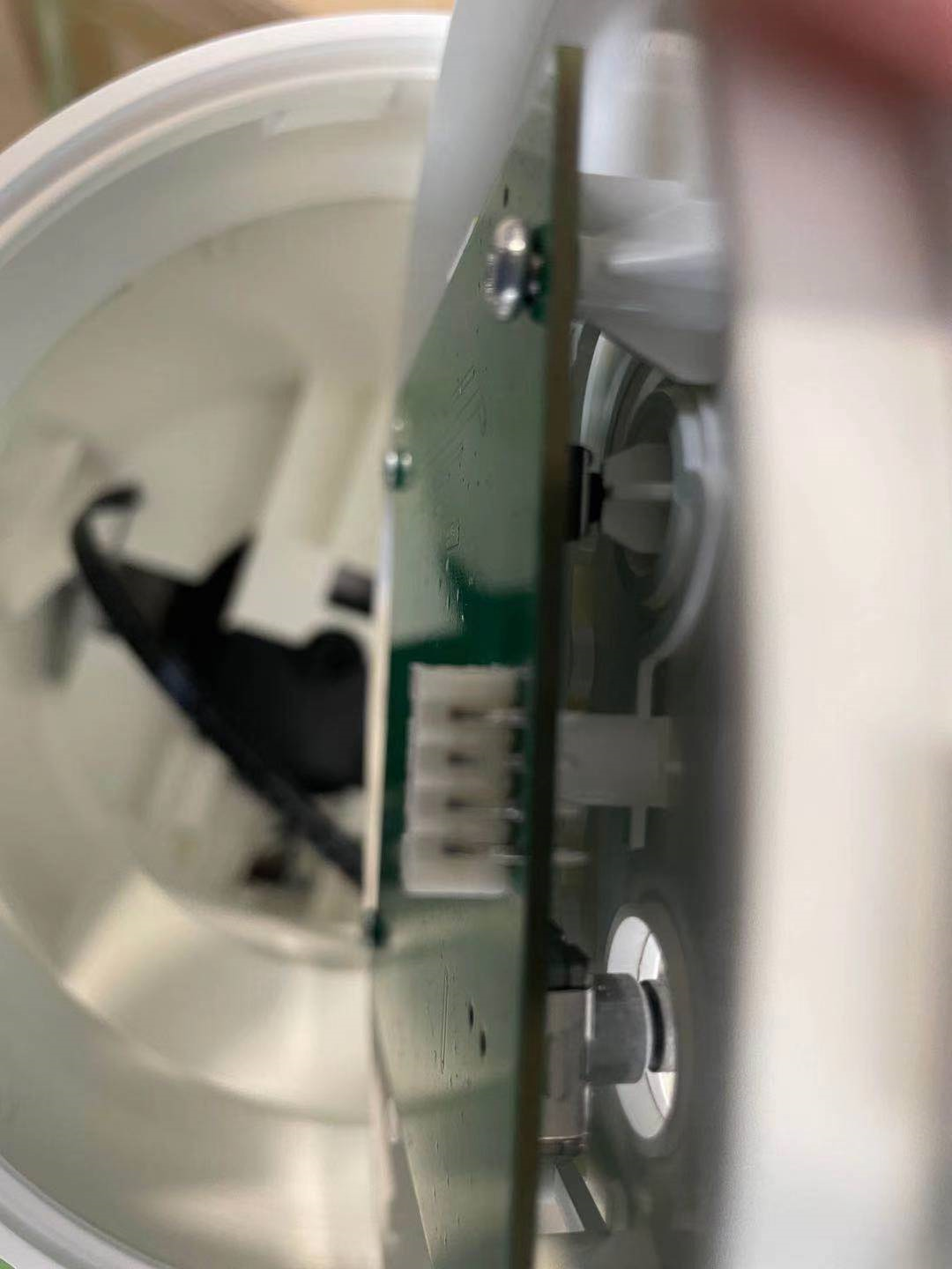
Wi-Fi module:
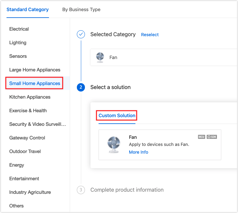
5: Product creation
-
Log in to the Tuya IoT Platform.
-
Click Small Home Appliances > Fan. Select Wi-Fi as the protocol.
-
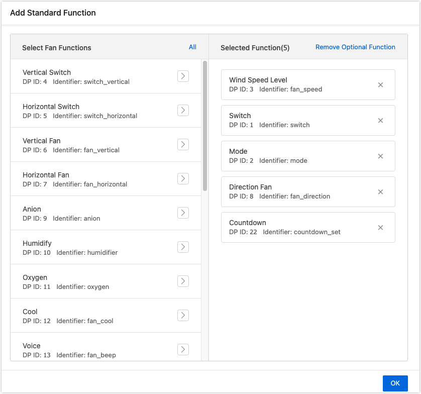
Add the required standard functions, which need to be mapped to embedded features.
-
Select the desired panel and go to hardware development. Select Tuya Standard Module SDK as the integration method and CBU module as the network module. Note that only the product ID that is added to the whitelist can select the CBU module. If you do not find the CBU module from the list, contact our technical support.
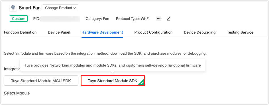
For more information, see Wi-Fi SDK Demo.
6: Embedded programming
Documents on GitHub
After you build the firmware, you need to upload the files on the Tuya IoT Platform. For more information, see Update Firmware.
1: Device pairing and network status indicator
Call tuya_iot_wf_gw_unactive() to enter pairing mode. The defined network status for Tuya module SDK is as follows.
typedef BYTE_T GW_WIFI_NW_STAT_E;
-
Press and hold to start pairing mode:
STATIC VOID wifi_key_process(TY_GPIO_PORT_E port,PUSH_KEY_TYPE_E type,INT_T cnt) { PR_DEBUG("port:%d,type:%d,cnt:%d",port,type,cnt); OPERATE_RET op_ret = OPRT_OK; UCHAR_T ucConnectMode = 0; if (port = WIFI_KEY_PIN) { if (LONG_KEY == type) { //press long enter linking network PR_NOTICE("key long press"); /* Remove a device manually */ tuya_iot_wf_gw_unactive(); } else if (NORMAL_KEY == type) { PR_NOTICE("key normal press"); } else { PR_NOTICE("key type is no deal"); } } return; } STATIC VOID wifi_config_init(VOID) { OPERATE_RET op_ret = OPRT_OK; /* Initialize the LED */ tuya_gpio_inout_set(WIFI_LED_PIN, FALSE); tuya_set_led_light_type(wifi_led_handle, OL_HIGH, 0, 0); // Turn off the LED. /* Initialize the LED */ op_ret = tuya_create_led_handle(WIFI_LED_PIN, TRUE, &wifi_led_handle); if (op_ret != OPRT_OK) { PR_ERR("key_init err:%d", op_ret); return; } tuya_set_led_light_type(wifi_led_handle, OL_HIGH, 0, 0); /* Initialize the button */ KEY_USER_DEF_S key_def; op_ret = key_init(NULL, 0, WIFI_KEY_TIMER_MS); if (op_ret != OPRT_OK) { PR_ERR("key_init err:%d", op_ret); return; } /* Initialize button parameters */ memset(&key_def, 0, SIZEOF(key_def)); key_def.port = WIFI_KEY_PIN; // Button I/O pins. key_def.long_key_time = WIFI_KEY_LONG_PRESS_MS; // Set the pressing and holding time. key_def.low_level_detect = WIFI_KEY_LOW_LEVEL_ENABLE; // TRUE: Low level is detected as a pressed button. FALSE: High level is detected as a pressed button. key_def.lp_tp = LP_ONCE_TRIG; // key_def.call_back = wifi_key_process; // Callback when a button is pressed. key_def.seq_key_detect_time = WIFI_KEY_SEQ_PRESS_MS; // Set the interval of continuous button-press. /* Register a button */ op_ret = reg_proc_key(&key_def); if (op_ret != OPRT_OK) { PR_ERR("reg_proc_key err:%d", op_ret); } return; } -
Wi-Fi status:
STATIC VOID wifi_state_led_reminder(IN CONST GW_WIFI_NW_STAT_E cur_stat)
{
	switch (cur_stat)
	{
		case STAT_LOW_POWER:    // Wi-Fi connection times out. The fan runs in low-power mode.
			tuya_set_led_light_type(wifi_led_handle, OL_HIGH, 0, 0); // Turn off the LED.
		break;

		case STAT_UNPROVISION: // The fan is waiting for a connection in EZ mode.
			tuya_set_led_light_type(wifi_led_handle, OL_FLASH_HIGH, WIFI_LED_FAST_FLASH_MS, 0xffff); // The LED flickers quickly.
		break;

		case STAT_AP_STA_UNCFG: // The fan is waiting for a connection in AP mode.
			tuya_set_led_light_type(wifi_led_handle, OL_FLASH_HIGH, WIFI_LED_LOW_FLASH_MS, 0xffff); // The LED flickers slowly.
		break;

		case STAT_AP_STA_DISC:
		case STAT_STA_DISC:     // The fan is being paired in EZ or AP mode.
			tuya_set_led_light_type(wifi_led_handle, OL_HIGH, 0, 0); // Turn off the LED.
		break;

		case STAT_CLOUD_CONN:
		case STAT_AP_CLOUD_CONN: // The module is connected to the Tuya IoT Cloud.
			tuya_set_led_light_type(wifi_led_handle, OL_LOW, 0, 0); // The LED is steady on.
		break;

		default:
		break;
	}
}
2: Fan mode
Besides the traditional fan speed control, we can design some wind modes specifically for different applications, such as standard wind, natural wind, and sleep wind. We use PWM signals to control the BLDC motor.
-
Switch fan mode:
VOID_T fan_speed_set(UINT_T speed) { UINT_T fan_speed_pwm_duty_cycle = 0; if (speed <= 0) { vSocPwmSetDuty(BLDC_PWM_ID, (BLDC_PWM_FAN_OFF)); return; } // The motor might not work properly if it runs for a long period when the PWM duty cycle is less than 30%. To resolve this problem, we set the PWM duty cycle to between 30% and 99%. fan_speed_pwm_duty_cycle = (UINT_T)(BLDC_PWM_FAN_MIN + ((BLDC_PWM_FAN_MAX - BLDC_PWM_FAN_MIN) * (speed / 100.0))); vSocPwmSetDuty(BLDC_PWM_ID, (fan_speed_pwm_duty_cycle)); return; } -
Standard wind mode:
static VOID_T fan_mode_normal(VOID_T) { INT_T opRet = LIGHT_OK; // Disable the timer of sleep wind mode to ensure the proper running of standard wind mode. opRet = opSocSWTimerStop(SLEEP_MODE_TIMER); if (opRet != LIGHT_OK) { PR_ERR("stop sleep timer error"); } // Disable the timer of natural wind mode to ensure the proper running of standard wind mode. opRet = opSocSWTimerStop(NATURAL_MODE_TIMER); if (opRet != LIGHT_OK) { PR_ERR("stop natural timer error"); } fan_speed_set(fan_state.speed); PR_NOTICE("+++ normal mode fan_state.speed : %d", fan_state.speed); } -
Natural wind mode:
static VOID_T fan_mode_natural_timer_cb(VOID_T) { // The function does nothing when the fan is shut down. if (fan_state.on_off == FALSE) { opSocSWTimerStop(NATURAL_MODE_TIMER); return; } if (natural_speed_low_flag) { PR_NOTICE("natural mode low speed"); fan_speed_set(1); } else { PR_NOTICE("natural mode high speed"); fan_speed_set(fan_state.speed); } natural_speed_low_flag = ~(natural_speed_low_flag); opSocSWTimerStart(NATURAL_MODE_TIMER, NATURAL_SPEED_CHANGE_TIME * 1000, fan_mode_natural_timer_cb); } static VOID_T fan_mode_natural(VOID_T) { INT_T opRet = LIGHT_OK; // Disable the timer of sleep wind mode to ensure the proper running of natural wind mode. opRet = opSocSWTimerStop(SLEEP_MODE_TIMER); if (opRet != LIGHT_OK) { PR_ERR("stop sleep timer error"); } natural_speed_low_flag = ~(0x00); fan_speed_set(fan_state.speed); opSocSWTimerStart(NATURAL_MODE_TIMER, NATURAL_SPEED_CHANGE_TIME * 1000, fan_mode_natural_timer_cb); } -
Sleep wind mode:
static VOID_T fan_sleep_mode_task(VOID_T)
{
	UINT8_T cur_gear;

	PR_NOTICE("enter fan_sleep_mode_task!");
	// Determine whether the current speed is the lowest level.
	if (fan_state.speed <= g_fan_speed_gear[0]) {
		fan_speed_set(g_fan_speed_gear[0]);
		change_fan_state();
		opSocSWTimerStop(SLEEP_MODE_TIMER);
		return;
	}

	cur_gear = get_cur_gear();
	PR_NOTICE("current gear is %d.", cur_gear);
	fan_state.speed = g_fan_speed_gear[--cur_gear];

	// Change the fan speed.
	fan_speed_set(fan_state.speed);
	fan_speed_led_set(get_cur_gear()+1);
	PR_NOTICE("speed change to %d.", fan_state.speed);
	// Write fan status to the flash memory.
	write_flash_fan_state();

	// Sleep wind mode starts. The fan speed steps down one level every one hour.
	opSocSWTimerStart(SLEEP_MODE_TIMER, SLEEP_SPEED_CHANGE_TIME * 1000, fan_sleep_mode_task);
}

static VOID_T fan_mode_sleep(VOID_T)
{
	UINT8_T cur_gear;
	INT_T opRet = LIGHT_OK;
	SHORT_T i;

	// Disable the timer of natural wind mode to ensure the proper running of sleep wind mode.
	opRet = opSocSWTimerStop(NATURAL_MODE_TIMER);
	if (opRet != LIGHT_OK) {
		PR_ERR("stop sleep timer error");
	}
	opRet = opSocSWTimerStop(SLEEP_MODE_TIMER);
	if (opRet != LIGHT_OK) {
		PR_ERR("stop sleep timer error");
	}

	// Determine the current speed level.
	cur_gear = get_cur_gear();
	fan_state.speed = g_fan_speed_gear[cur_gear];
	// Change the fan speed.
	fan_speed_set(fan_state.speed);
	PR_NOTICE("speed change to %d.", fan_state.speed);
	// Write fan status to the flash memory.
	write_flash_fan_state();

	opSocSWTimerStart(SLEEP_MODE_TIMER, SLEEP_SPEED_CHANGE_TIME * 1000, fan_sleep_mode_task);
}
3: Encoder and button
-
Initialize buttons:
VOID_T fan_key_init(VOID_T) { OPERATE_RET opRet; tuya_gpio_inout_set(KEY_ROTARY_A, TRUE); tuya_gpio_inout_set(KEY_ROTARY_B, TRUE); /* Initialize detection of knob rotation */ BkGpioEnableIRQ(KEY_ROTARY_A, IRQ_TRIGGER_FALLING_EDGE, knod_key_cb, NULL); opRet = key_init(NULL, 0, 0); if (opRet != OPRT_OK) { PR_ERR("key_init err:%d", opRet); return; } memset(&KEY_DEF_T, 0, SIZEOF(KEY_DEF_T)); KEY_DEF_T.port = KEY_ROTARY_N; KEY_DEF_T.long_key_time = 3000; KEY_DEF_T.low_level_detect = TRUE; KEY_DEF_T.lp_tp = LP_ONCE_TRIG; KEY_DEF_T.call_back = key_press_cb; KEY_DEF_T.seq_key_detect_time = 400; opRet = reg_proc_key(&KEY_DEF_T); if (opRet != OPRT_OK) { PR_ERR("reg_proc_key err:%d", opRet); return; } KEY_DEF_T.port = KEY_TIMER; opRet = reg_proc_key(&KEY_DEF_T); if (opRet != OPRT_OK) { PR_ERR("reg_proc_key err:%d", opRet); return; } KEY_DEF_T.port = KEY_POWER; KEY_DEF_T.long_key_time = 10000; opRet = reg_proc_key(&KEY_DEF_T); if (opRet != OPRT_OK) { PR_ERR("reg_proc_key err:%d", opRet); return; } } -
Button callback:
We use the external interrupt to implement encoder functions. When an external interrupt is triggered, we can determine the motor rotation direction by the voltage level on pin A and pin B. If the two pins have the same level, it means counterclockwise rotation. Otherwise, it is a clockwise rotation.
STATIC VOID_T knod_key_cb(VOID_T) { INT8_T current_gear; // The function does nothing when the fan is shut down. if (fan_state.on_off == FALSE) { return; } BkGpioFinalize(KEY_ROTARY_A); // Returns the current speed level. current_gear = get_cur_gear(); if(tuya_gpio_read(KEY_ROTARY_A) != tuya_gpio_read(KEY_ROTARY_B)) { PR_DEBUG("A != B"); // Clockwise rotation. current_gear++; if (current_gear > (MAX_GEAR_NUMBER-1)) { current_gear = (MAX_GEAR_NUMBER-1); } fan_state.speed = g_fan_speed_gear[current_gear]; } else { PR_DEBUG("A == B"); // Counterclockwise rotation. current_gear--; if (current_gear < 0) { current_gear = 0; } fan_state.speed = g_fan_speed_gear[current_gear]; } /* Change fan status: speed, mode, and LED */ change_fan_state(); write_flash_fan_state(); PR_DEBUG("fan current_gear is : %d", current_gear); /* Initialize detection of knob rotation */ BkGpioEnableIRQ(KEY_ROTARY_A, IRQ_TRIGGER_FALLING_EDGE, knod_key_cb, NULL); } -
Callbacks for normal buttons:
STATIC VOID_T key_press_cb(TY_GPIO_PORT_E port,PUSH_KEY_TYPE_E type,INT_T cnt)
{
	PR_DEBUG("port: %d, type: %d, cnt: %d", port, type, cnt);

	/* Button for knob */
	if (port == KEY_ROTARY_N) {
		if (fan_state.on_off == FALSE) {
			return;
		}
		switch (type) {
			case NORMAL_KEY:
				PR_DEBUG("knod press.");

				if (fan_state.mode == NORMAL_MODE) {
					fan_state.mode = NATURAL_MODE;
				} else if (fan_state.mode == NATURAL_MODE) {
					fan_state.mode =SLEEP_MODE;
				} else {
					fan_state.mode = NORMAL_MODE;
				}
				change_fan_state();
				break;
			case LONG_KEY:
				PR_DEBUG("knod long press.");
				/* Reset and delete all users to restore to default mode */
				fan_state = fan_default_state;
				change_fan_state();
				write_flash_fan_state();
				break;

			case SEQ_KEY:
				PR_DEBUG("knod SEQ press, the count is %d.", cnt);
				break;

			default:
				break;
		}
	}

	/* Button for timer */
	if (port == KEY_TIMER) {
		if (fan_state.on_off == FALSE) {
			return;
		}
		switch (type) {
			case NORMAL_KEY:
				PR_DEBUG("timer press.");
				if (fan_state.local_timing == 0xFF) {
					fan_state.local_timing = 1;
				} else if (fan_state.local_timing >= 4) {
					fan_state.local_timing = 0xFF; // Timer is cancelled.
				} else {
					fan_state.local_timing++;
				}
				fan_local_timing_shutdown();
				break;
			case LONG_KEY:
				PR_DEBUG("timer long press.");

				break;
			case SEQ_KEY:
				PR_DEBUG("timer SEQ press, the count is %d.", cnt);

				break;
			default:
				break;
		}
	}

	/* Button for power switch */
	if (port == KEY_POWER) {
		switch (type) {
			case NORMAL_KEY:
				if (fan_state.on_off == FALSE) {
					fan_state.on_off = TRUE;
					PR_DEBUG("Turn on");
				} else {
					fan_state.on_off = FALSE;
					PR_DEBUG("Turn off");
				}
				change_fan_state();
				break;
			case LONG_KEY:
				PR_DEBUG("power long press.");

				break;
			case SEQ_KEY:
				PR_DEBUG("power SEQ press, the count is %d.", cnt);

				break;
			default:
				break;
		}
	}
	write_flash_fan_state();
}
4: Local timer
The timer is one of the useful smart features for devices like the fan, air conditioner, diffuser, and many more.
We call a software timer to implement a local timer.
VOID_T fan_timing_cd(VOID_T)
{
	fan_state.local_timing--;
	opSocSWTimerStop(SHUTDOWN_TIMER);
	if (fan_state.local_timing == 0 || fan_state.on_off == FALSE) {
		fan_turn_off();
	} else {
		PR_NOTICE("fan_state.local_timing ======== %d", fan_state.local_timing);
		write_flash_fan_state();
		opSocSWTimerStart(SHUTDOWN_TIMER, (SINGLE_TIMING*1000), fan_timing_cd);
		fan_local_timing_led_set(fan_state.local_timing);
	}
}

VOID_T fan_local_timing_shutdown(VOID_T)
{
	fan_local_timing_led_set(fan_state.local_timing);
	if (fan_state.local_timing > 4) { // Timer is off.
		opSocSWTimerStop(SHUTDOWN_TIMER);
		return;
	}
	PR_NOTICE("run shutdown timer");
	opSocSWTimerStop(SHUTDOWN_TIMER);
	opSocSWTimerStart(SHUTDOWN_TIMER, (SINGLE_TIMING*1000), fan_timing_cd);
}
5: Power-off memory
In case of power failure, the power-off memory feature enables the fan to resume its previous status after power-on.
This feature writes the current device information to the flash memory after each status change. After the fan is powered on, it will read the data stored in the flash memory to set the status.
VOID_T read_flash_fan_state(VOID_T)
{
	INT_T opRet, i;
	UCHAR_T fan_state_data_crc;
	UCHAR_T before_fan_power_off_state[FAN_STATE_STORAGE_LEN]; // The status of the fan before power-off.

	opRet = uiSocFlashRead(SAVE_TYP1, FAN_STATE_OFFSET, FAN_STATE_STORAGE_LEN*SIZEOF(UCHAR_T), before_fan_power_off_state);
	if (opRet != FAN_STATE_STORAGE_LEN) {
		PR_ERR("read data error for Flash");
		return;
	}

	// Determine whether the header data is correct.
	if (before_fan_power_off_state[0] != FAN_DATA_HEAD) {
		PR_ERR("data head error");
		return;
	}

	fan_state_data_crc = get_crc_8(before_fan_power_off_state, (FAN_STATE_STORAGE_LEN - 1)*SIZEOF(UCHAR_T));
	// Verify the data.
	if (fan_state_data_crc != before_fan_power_off_state[FAN_STATE_STORAGE_LEN - 1]) {
		PR_ERR("crc error, before_fan_power_off_state[%d] = %02x, crc data = %02x.", FAN_STATE_STORAGE_LEN - 1, before_fan_power_off_state[FAN_STATE_STORAGE_LEN - 1], fan_state_data_crc);
		return;
	}

	// Store the data read from the flash memory into the struct.
	fan_state.on_off    = before_fan_power_off_state[FLASH_FAN_STATE_ON_OFF];
	fan_state.mode      = before_fan_power_off_state[FLASH_FAN_STATE_MODE];
	fan_state.speed     = before_fan_power_off_state[FLASH_FAN_STATE_SPEED];
	fan_state.local_timing = before_fan_power_off_state[FLASH_FAN_STATE_TIMING];

	return;
}

VOID_T write_flash_fan_state(VOID_T)
{
	INT_T opRet, i;
	UCHAR_T fan_state_buffer[FAN_STATE_STORAGE_LEN];

	fan_state_buffer[0] = FAN_DATA_HEAD;
	fan_state_buffer[1] = fan_state.on_off;
	fan_state_buffer[2] = fan_state.mode;
	fan_state_buffer[3] = fan_state.speed;
	fan_state_buffer[4] = fan_state.local_timing;
	fan_state_buffer[5] = get_crc_8(fan_state_buffer, (FAN_STATE_STORAGE_LEN - 1)*SIZEOF(UCHAR_T));

	for (i=0; i<FAN_STATE_STORAGE_LEN; i++) {
		PR_NOTICE(" +++ fan_state_buffer is [%d] : %02x", i, fan_state_buffer[i]);
	}

	opRet = opSocFlashWrite(SAVE_TYP1, FAN_STATE_OFFSET, fan_state_buffer, FAN_STATE_STORAGE_LEN * SIZEOF(UCHAR_T));
	if (opRet != LIGHT_OK) {
		PR_ERR("write Flash error");
	}

	return;
}
6: Restore factory defaults
When the fan is reset, it will restore factory defaults. This feature can set the device status in the flash memory to the initial value or directly erase the current information.
VOID_T erase_flash_fan_state(VOID_T)
{
	INT_T opRet, i;
	UCHAR_T fan_state_buffer[FAN_STATE_STORAGE_LEN];

	fan_state.on_off = FALSE;
	fan_state.mode   = NORMAL_MODE;
	fan_state.speed  = 1;

	fan_state_buffer[0] = FAN_DATA_HEAD;
	fan_state_buffer[1] = FALSE;    //fan_state.on_off
	fan_state_buffer[2] = NORMAL_MODE; //fan_state.mode
	fan_state_buffer[3] = 1;        //fan_state.speed
	fan_state_buffer[4] = 0xFF;     // fan_state.local_timing
	fan_state_buffer[5] = get_crc_8(fan_state_buffer, (FAN_STATE_STORAGE_LEN - 1)*SIZEOF(UCHAR_T));

	for (i=0; i<FAN_STATE_STORAGE_LEN; i++) {
		PR_NOTICE(" +++ fan_state_buffer is [%d] : %02x", i, fan_state_buffer[i]);
	}

	opRet = opSocFlashWrite(SAVE_TYP1, FAN_STATE_OFFSET, fan_state_buffer, FAN_STATE_STORAGE_LEN * SIZEOF(UCHAR_T));
	if (opRet != LIGHT_OK) {
		PR_ERR("write Flash error");
	}

	return;
}
7: Switch fan mode
Call this function to switch fan mode on the app. For example, switch from standard wind mode to sleep wind mode. Alternatively, the mode can be switched manually by the button.
VOID_T change_fan_state(VOID_T)
{
	if (fan_state.on_off == FALSE) {
		fan_turn_off();
		hw_report_all_dp_status();
		PR_NOTICE("stop sleep & natural timer");
		return;
	}

	if (fan_state.bright == 1) {
		fan_led_dimmer(100);
	} else {
		fan_led_dimmer(900);
	}

	if (fan_state.mode == SLEEP_MODE) {
		PR_NOTICE("enter sleep mode");
		fan_mode_sleep();
	} else if (fan_state.mode == NATURAL_MODE) {
		PR_NOTICE("enter natural mode");
		fan_mode_natural();
	} else {
		PR_NOTICE("enter normal mode");
		fan_mode_normal();
	}

	hw_report_all_dp_status();

	/* speed LED set */
	fan_speed_led_set(get_cur_gear()+1);
	fan_mode_led_set();

	return;
}
7: Remote control
After you complete the development, you can connect the fan to a Wi-Fi network and control the fan remotely. The control methods can be voice, remote controller, mobile phone, tablet, or self-developed physical button.
Install the Tuya Smart app on your mobile phone. Pair the fan and connect it to the Tuya IoT Cloud to implement remote control.
For more information, see App Development.
8: Learn more
This section provides more information about the hardware for your reference.
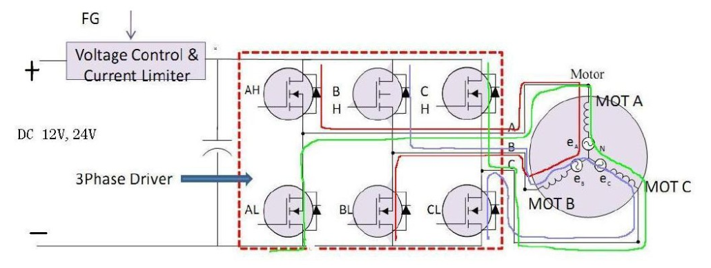
Current flow of BLDC motor
-
The current flow marked in red: The current flows from the AH high-side MOSFET to MOT A. Then, it flows from MOT B to the negative terminal through the BL low-side MOSFET.
-
The current flow marked in blue: The current flows from the BH high-side MOSFET to MOT B. Then, it flows from MOT C to the negative terminal through the CL low-side MOSFET.
-
The current flow marked in green: The current flows from the CH high-side MOSFET to MOT C. Then, it flows from MOT A to the negative terminal through the AL low-side MOSFET.
FU6832S chip and BLDC motor
The FU6832S chip has built-in pull-up and pull-down resistors. There are six designated pins H_PU, H_PV, H_PW, L_U, L_V, and L_W for controlling the three-phase BLDC motor. The maximum high level is the VCC voltage.
| Pin | FU6832 | Types | Function |
|---|---|---|---|
| H_PU | 28 | DO | 3P3N pre-driver, high side phase U output, built-in 47 kΩ pull-up resistor |
| H_PV | 29 | DO | 3P3N pre-driver, high side phase V output, built-in 47 kΩ pull-up resistor |
| H_PW | 30 | DO | 3P3N pre-driver, high side phase W output, built-in 47 kΩ pull-up resistor |
| L_U | 31 | DO | 3P3N pre-driver, low side phase U output, built-in 25 kΩ pull-down resistor |
| L_V | 32 | DO | 3P3N pre-driver, low side phase V output, built-in 25 kΩ pull-down resistor |
| L_W | 33 | DO | 3P3N pre-driver, low side phase W output, built-in 25 kΩ pull-down resistor |
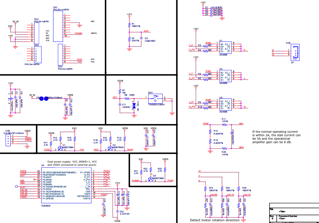
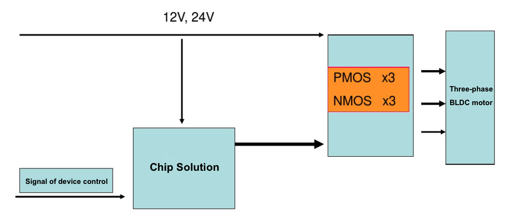
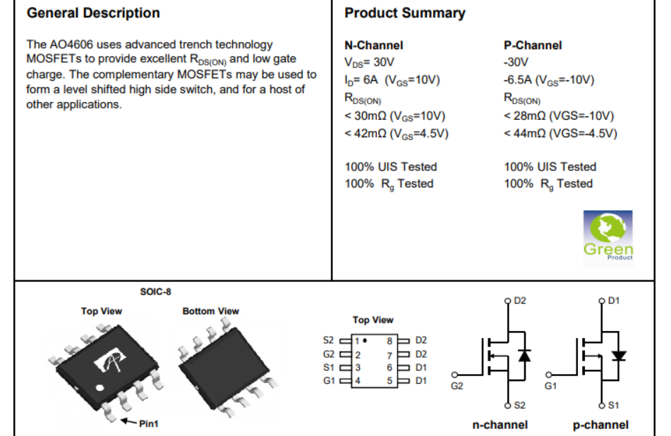
If the input voltages of the chip’s power supply are the same as the operating voltage of the motor, the peripheral level-shifting circuit is not required. You can use three AO4606 chips to drive the three pins U, V, and W on the motor. AO4606 has one nMOS and one pMOS, which support the design of a half-bridge driver circuit.
The FU6832S chip has a built-in independent operational amplifier with configurable gain. Add a peripheral sampling resistor to detect motor overcurrent.
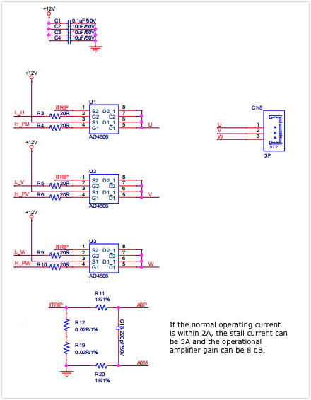
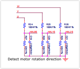
The voltage of the circuit for monitoring motor rotation direction is stepped down. Then, the current flows into pins 14, 15, and 16 on the FU6832S chip.
The digital pins on the FU6832S chip run at 5V while the pins on the Wi-Fi module run at 3.3V. Therefore, we need a level shifting circuit.
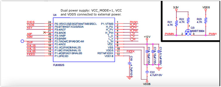
CBU network module
The CBU module is composed of a highly integrated radio-frequency identification (RFID) chip BK7231N and a few peripheral components. It supports a dual connection of AP and station as well as Bluetooth connection. It can run up to 120 MHz and feature 2 MB flash memory and 256 KB RAM. The module has 16 I/O pins. It supports peripherals including PWM, UART, and SPI. The built-in 32-bit CPU and six PWM outputs are ideal for high-quality LED control systems. For more information, see CBU Module Datasheet.
Is this page helpful?
YesSuggestions


