Empower Desk Lamp with Smart Sensing

Overview
The traditional desk lamp can illuminate your work area, but retrofitted with some sensors and circuits, it will help to boost your personal productivity with its smart, automated, and friendly features.
Features
- Smart sensing: Detects the human presence and triggers the lamp on or off accordingly.
- Auto-brightness adjustment: Dims and brightens the light automatically according to the surroundings for comfortable illumination that reduces eye discomfort and saves energy.
- Sitting position detection: Detects sitting position and sends a reminder when any incorrect position is detected.
- Rest reminder: Allows you to set a rest reminder for proper planning of eye time.
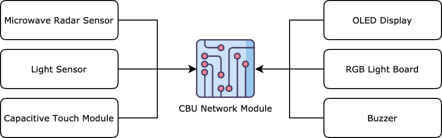
Block diagram of hardware
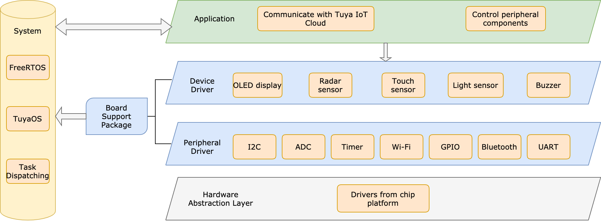
Block diagram of software
Materials
CBU network module
Count:1A low-power Wi-Fi and Bluetooth Low Energy combo module developed by Tuya Smart. It can work with functional boards to implement your required device features.more
ISK1101 microwave radar sensor
Count:1It can detect the difference between the transmitted wave and reflection wave to judge whether there is an object moving over the microwave radar sensor. This radar sensor has a single-input and single-output (SISO) mmWave antenna, mmWave sensor chip from ICLEGEND MICRO, and MCU inside. It is also easy to be developed because of its debugging interface.
BH1750 light sensor
Count:1It is used to detect light intensity and has a BH1750FVI, a digital ambient light sensor IC for the I2C bus interface. This sensor can accurately measure the LUX value of light up to 65535 lx.
Capacitive touch switch module
Count:1The module is based on a touch-sensing IC (TTP223B) and outputs low in the normal state.
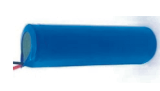
Lithium battery
Count:13.7V to 4.25V
Lithium battery charger and protection module
Count:1This module can safely charge a lithium battery and provides necessary protection such as overcurrent protection.
Voltage regulator module
Count:1It is used to provide a microprocessor with the appropriate supply voltage.
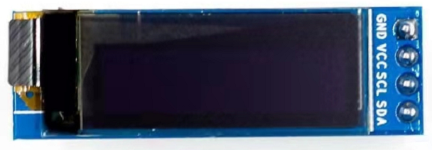
0.91 inch OLED display
Count:1Display time and battery level.
Buzzer
Count:1Deliver timer prompts and low battery alerts.
Steps
Step 1: Hardware design
Module
A low-power Wi-Fi and Bluetooth Low Energy combo module developed by Tuya Smart. It can work with functional boards to implement your required device features.
-
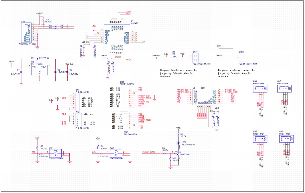
Schematic diagram (Download)
-
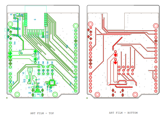
PCB design (Download)
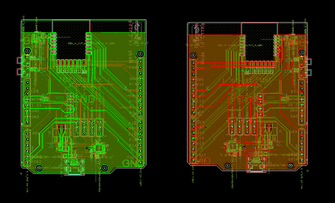
-
PCB soldering
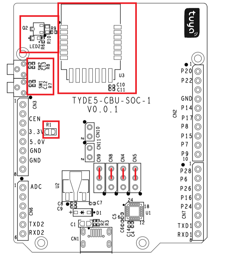
Note: The rectangle in red marks where solder is required in our prototype. Connect CN9, CN8, N4, and CN5 jumpers according to the red lines.
-
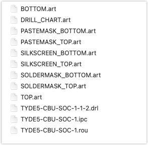
Gerber file of the PCB (Download)
-
BOM (Download)
ID Description Location Packaging Quantity 1 0.1 μF/10V C10, C12, C13 c0402 3 2 10 μF/6.3V C11 c0402 1 3 HS211UR13-02 LED2 led0603 1 4 0R R1 r0805 1 5 MMBT3904 Q2 sot23-3 1 6 1K/1% R6, R9 r0402 2 7 10K/1% R7, R8 r0402 2 8 10k/1% R10 r0603 1 9 CBU U3 moudle-cbu-4-21 1
Sensors
-
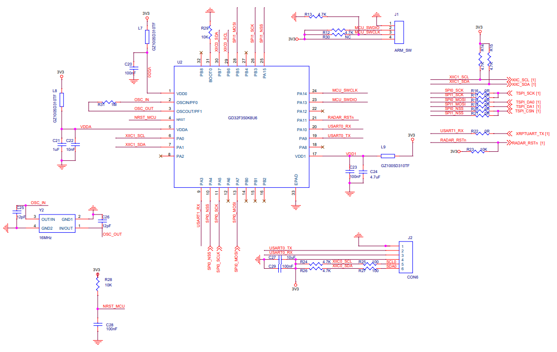
ISK1101 microwave radar sensor (Download)
ISK1101 can detect the difference between the transmitted wave and reflection wave to judge whether there is an object moving over the microwave sensor.
This radar sensor has a single-input and single-output (SISO) mmWave antenna, mmWave sensor chip from ICLEGEND MICRO, and MCU inside. It is also easy to be developed because of its debugging interface.
With the characteristics of high integration and high bandwidth, the mmWave sensor allows us to evaluate most of the applications in a compact kit.
With the mmWave radar-sensing technology, this sensor enables the detection of human presence and presence duration within a configurable range and sends a control signal accordingly. It can distinguish between humans and still objects and supports the setting of detection range and threshold for triggering a signal.
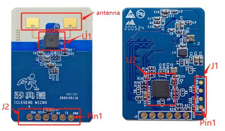
Component description
Name Brand Model Description U1 ICLEGEND MICRO S3KM111 mmWave sensor U2 GigaDevice GD32F350K8U6 MCU Pin configuration
Name Feature Description J1 Includes 3v3, RX, TX, and GND pins. The RX and TX pins are used for UART communication. An extra I2C pin is provided. Pin pitch of 2.54 mm. J2 Includes 3v3, SWCLK, SWDIO, and GND pins. SWCLK and SWDIO pins are used for debugging and downloading MCU software. Contacts pitch of 2.54 mm. -
Schematic diagram

-
PCB
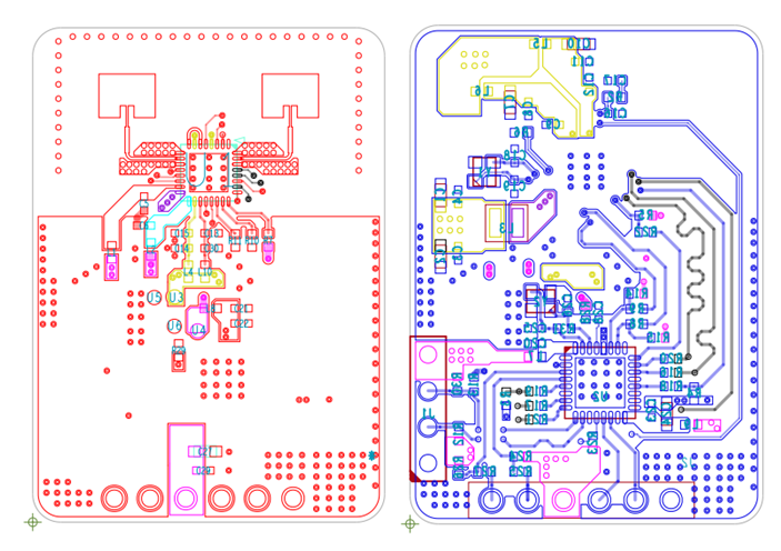
-
-
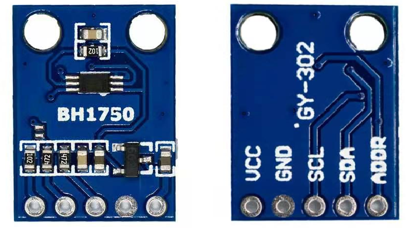
BH1750 light sensor (Download)
BH1750 is a digital ambient light sensor that uses I2C to communicate.
It is used to detect light intensity and has a BH1750FVI, a digital ambient light sensor IC for the I2C bus interface. This sensor can accurately measure the LUX value of light up to 65535 lx.
Schematic diagram
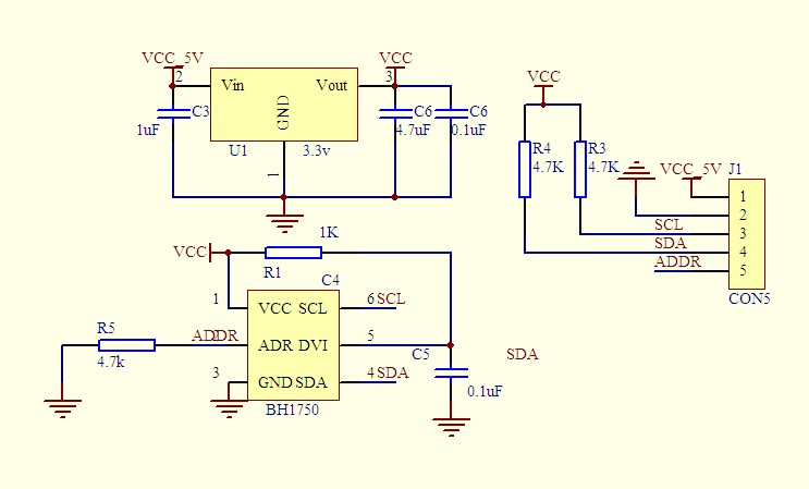
Pin configuration
Name Description VCC 3V to 5V GND Ground SCL I2C serial clock line SDA I2C serial data line ADDR Address -
Capacitive touch switch module
The module is based on a touch-sensing IC (TTP223B) and outputs low in the normal state.
-
If there is a touch around the sensing area on the back of the module, the module will output a high level.
-
In this project, we leave jumper A and jumper B open.
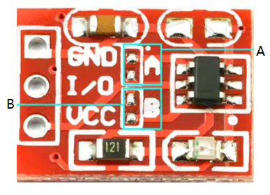
Pin configuration
Pin Description VCC 2.5V to 5.5V I/O Outputs low in the normal state. GND Ground Mode of operations
Lock state and TTL level output Jumper A Jumper B No-lock and high TTL level output Open Open No-lock and low TTL level output Close Open Self-lock and high TTL level output Open Close Self-lock and low TTL level output Close Close -
Other units
-
One lithium battery (supply voltage: 3.7V to 4.25V)
-
Lithium battery charger and protection module
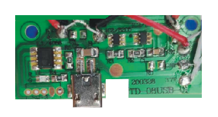
Specification
Input voltage Charging current Charging cut-off voltage Battery over-discharge protection voltage Battery overcurrent protection current 5V ≤ 1000 mA 4.2V 2.5V 3A Current adjustment
RPROG (K) IBAT (mA) 30 50 20 70 10 130 5 250 4 300 2 580 1.66 690 1.5 780 1.33 900 1.2 1000 Note:
- When the battery is connected for the first time, there may be no voltage output. You need to charge the battery with 5V input to activate the protection circuit.
- If the battery is disconnected from the module and connected again, you also need to activate the protection circuit.
- If a mobile phone power adapter is used for input, the output current must be 1A or above. Otherwise, the charging may not work properly.
- If the input voltage is high, such as 5.2V or 5.5V, the charging current cannot reach 1000 mA. This is a normal phenomenon. When the voltage is too high, the chip will automatically reduce the charging current to protect the chip from burning. It is normal that the temperature of the chip is around 60°C during operation.
- Input reverse connection has no effect on the chip, but the output (battery end) reverse will burn the chip.
- Solder two sampling resistors on where the voltage is output, between the 3.7V and GND pins. You must not solder them on where the battery is connected.
- You can adjust the resistor value of R5 to change the output current. We changed the resistor value to 1.2 kΩ.
-
Voltage regulator module
A buck-boost converter can provide both a step-up operation and a step-down operation by controlling the switches, thus accurately providing the required voltage level of the output voltage.

Specification
Input voltage Output voltage Efficiency Output current Quiescent current 1.8V to 5.5V DC 3.3V DC 96% The maximum current of 2A Less than 50 μA device quiescent current Pin configuration
Pin Description VIN Positive input voltage GND Negative input voltage VOU Output voltage GND Negative output voltage Note: Use a thicker solder wire to connect components because we have found that connection with jumpers cannot deliver the required power.
-
OLED display (Download)
Display time and battery level.
Schematic diagram
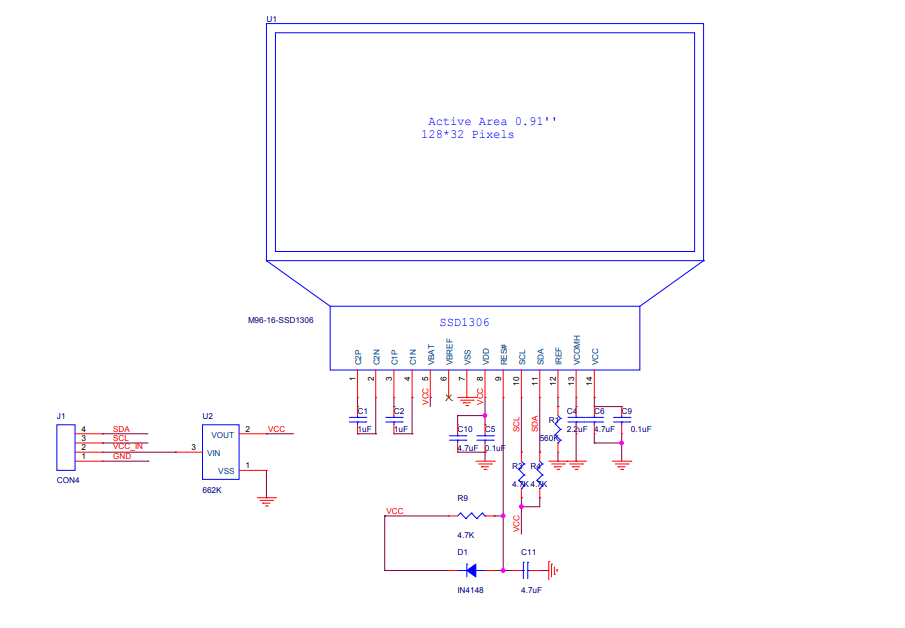
Pin configuration
Pin Description VCC 3.3V to 6V GND Ground SCL I2C serial clock line SDA I2C serial data line -
Buzzer (Download)
It can deliver timer prompts and low battery alerts. You can pull up the pin on the MCU to control the buzzer.
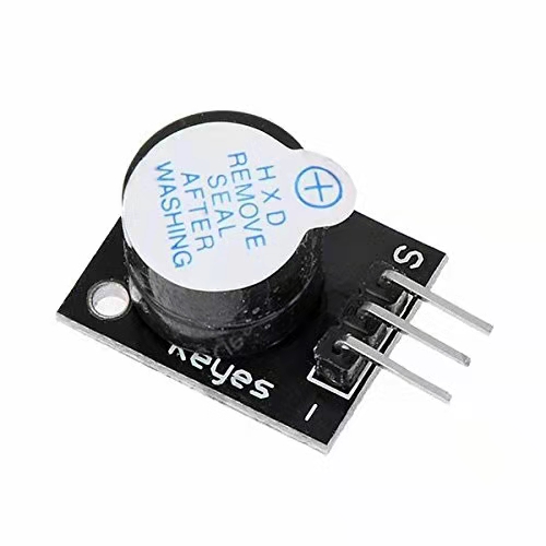
Pin configuration
Pin Description S Ground VCC 1.5V to 15V -Signal pin Note: Due to the reversed printing of the buzzer used in this project, we connect the
Spin to the ground and-pin to the I/O pin.
Step 2: Prototype assembly
Schematic diagram
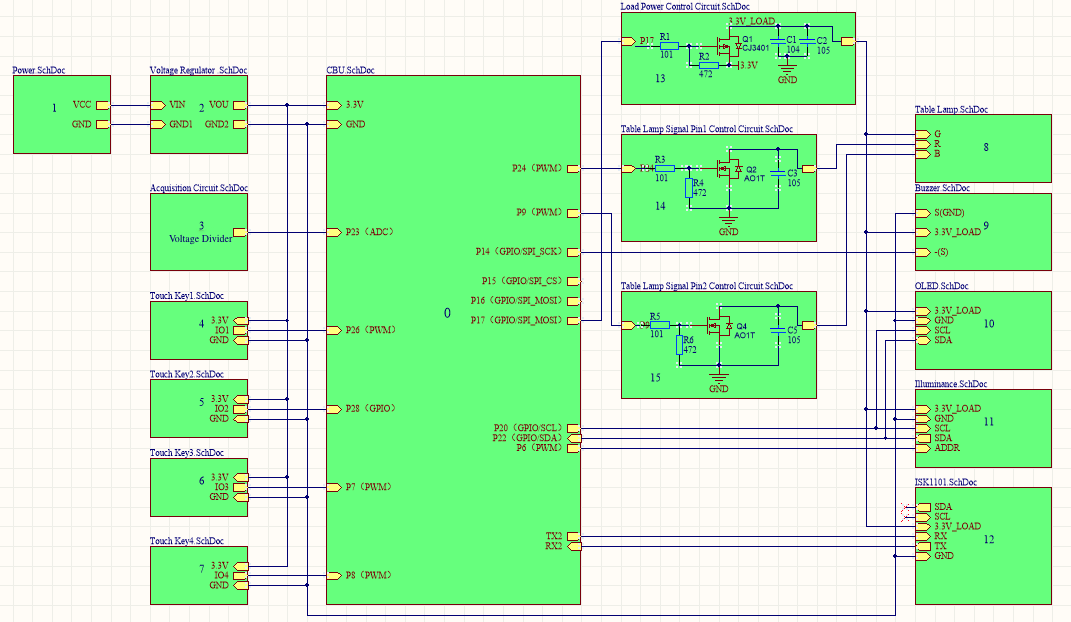
Schematic description
| Block ID | Meaning |
|---|---|
| 1 | Lithium battery for power supply. |
| 2 | Voltage regulator module for outputting 3.3V voltage. |
| 3 | Data acquisition circuit. Two 100 kΩ resistors connected in series work as a voltage divider. We solder the two resistors between the 3.7V and GND pins. |
| 4 | Touch key 1 for power switch. |
| 5 | Touch key 2 for setting. |
| 6 | Touch key 3 for up control. |
| 7 | Touch key 4 for down control. |
| 8 | Light board, consisting of 50 single-color LED lights. 25 lights are connected in series in one set. |
| 9 | Buzzer module. |
| 10 | OLED display. |
| 11 | Light sensor. |
| 12 | Radar sensor. |
| 13 | Low-power control circuit. |
| 14 | Signal pin 1 on the control circuit of the desk lamp. |
| 15 | Signal pin 2 on the control circuit of the desk lamp. |
Wiring diagram
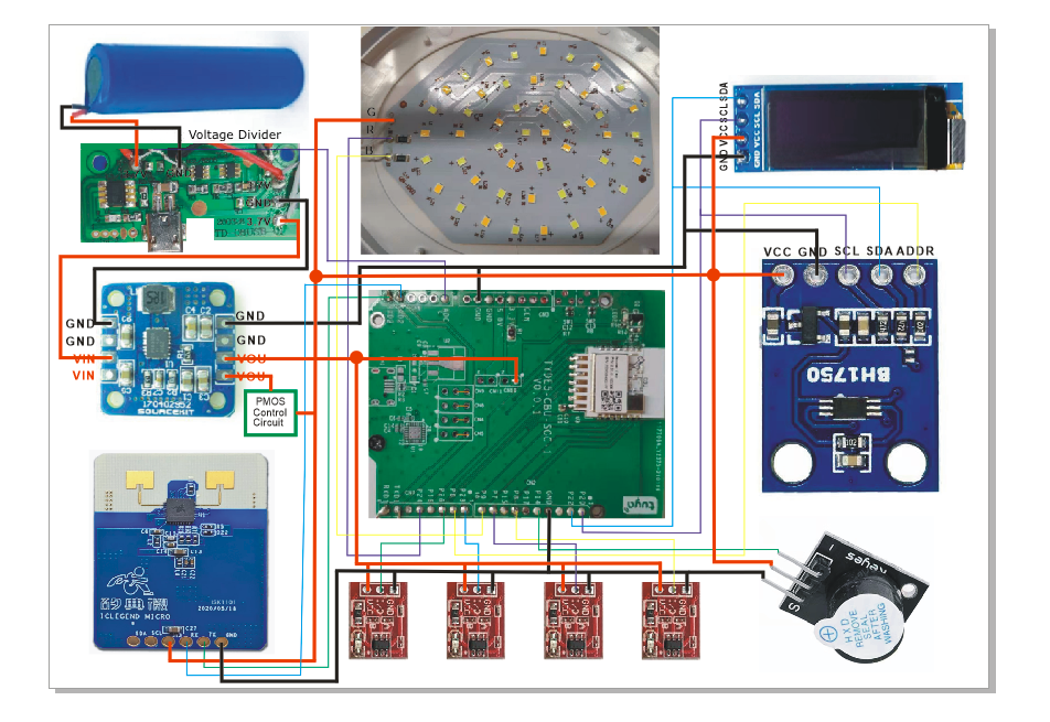
Note:
- The I/O 17 on the MCU controls p-channel MOSFET to supply power to the OLED display, radar sensor, light sensor, and buzzer.
- The R and B pins on the light board are connected to the signal pins on the MCU through the n-channel MOSFET.
Step 3: Operation on Tuya IoT Platform
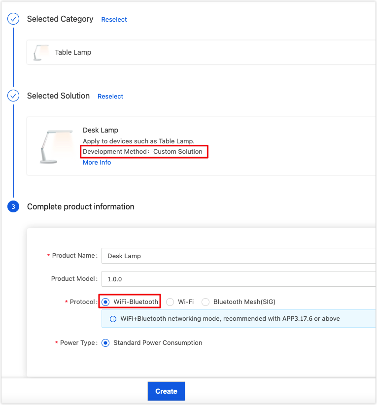
This section describes how to create a desk lamp on the Tuya IoT Platform. For more information, see Create Products.
-
Log in to the Tuya IoT Platform.

-
Click Lighting > Table Lamp.
-
Click the Custom Solution tab. Enter a product name, select WiFi+Bluetooth as the protocol type, and click Create at the bottom of this page.
-
-
Select the required standard functions and create three custom functions, as shown below.

-
When you complete the function definition, click Device Panel to select a favorite app control panel. It is recommended to select the Debugging Panel to suit your debugging needs.
You have finished creating a product on the Tuya IoT Platform. It is ready to proceed with embedded system development.
Step 4: Embedded programming
The embedded code is based on the BK7231n chipset and developed with Tuya’s general Wi-Fi SDK. You can download the routine and find the sample code.
Application layer
Extract the downloaded routine zip file. There are two folders include and src. The structure of the application code is as follows:
├── src
| ├── app_driver
| | ├── lamp_pwm.c           // Lamp PWM driver.
| | ├── sh1106.c             // OLED driver.
| | ├── bh1750.c             // Light sensor driver.
| | └── app_key.c            // Code of touch keys.
| ├── app_soc                // Interfaces of SoC layer.
| ├── tuya_device.c          // Entry file of the application layer.
| ├── app_lamp.c             // Main application layer.
| └── lamp_control.c         // Logic of key control.
|
├── include                  // Header files.
| ├── app_driver
| | ├── lamp_pwm.h
| | ├── sh1106.h
| | ├── bh1750.h
| | └── app_key.h
| ├── app_soc
| ├── tuya_device.h
| ├── app_lamp.h
| └── lamp_control.h
|
└── output                  // Production
Open tuya_device.c and find the function device_init.
OPERATE_RET device_init(VOID_T)
{
	OPERATE_RET op_ret = OPRT_OK;

	TY_IOT_CBS_S wf_cbs = {
		status_changed_cb,\
		gw_ug_inform_cb,\
		gw_reset_cb,\
		dev_obj_dp_cb,\
		dev_raw_dp_cb,\
		dev_dp_query_cb,\
		NULL,
	};

	op_ret = tuya_iot_wf_soc_dev_init_param(WIFI_WORK_MODE_SEL, WF_START_SMART_FIRST, &wf_cbs, NULL, PRODECT_ID, DEV_SW_VERSION);
	if(OPRT_OK != op_ret) {
		PR_ERR("tuya_iot_wf_soc_dev_init_param error,err_num:%d",op_ret);
		return op_ret;
	}

	op_ret = tuya_iot_reg_get_wf_nw_stat_cb(wf_nw_status_cb);
	if(OPRT_OK != op_ret) {
		PR_ERR("tuya_iot_reg_get_wf_nw_stat_cb is error,err_num:%d",op_ret);
		return op_ret;
	}

	op_ret = app_lamp_init(APP_LAMP_NORMAL);
	if(OPRT_OK != op_ret) {
		PR_ERR("app init err!");
		return op_ret;
	}

	return op_ret;
}
In the development environment for the BK7231 chipset, the device_init function is the entry to the application code. When the device is powered on, the adaptation layer runs the initialization code and then calls this function to initialize the application layer.
This function can initiate three types of requests.
-
Call
tuya_iot_wf_soc_dev_init_param()to initialize the SDK.- Specify the working mode and device pairing mode.
- Register callbacks and store the product ID (PID). The macro for the PID is
PRODECT_KEY.
TY_IOT_CBS_S wf_cbs = { status_changed_cb,\ gw_ug_inform_cb,\ gw_reset_cb,\ dev_obj_dp_cb,\ dev_raw_dp_cb,\ dev_dp_query_cb,\ NULL, }; op_ret = tuya_iot_wf_soc_dev_init_param(WIFI_WORK_MODE_SEL, WF_START_SMART_FIRST, &wf_cbs, NULL, PRODECT_ID, DEV_SW_VERSION); if(OPRT_OK != op_ret) { PR_ERR("tuya_iot_wf_soc_dev_init_param error,err_num:%d",op_ret); return op_ret; } -
Call
tuya_iot_reg_get_wf_nw_stat_cb()to register callback of device network status.op_ret = tuya_iot_reg_get_wf_nw_stat_cb(wf_nw_status_cb); if(OPRT_OK != op_ret) { PR_ERR("tuya_iot_reg_get_wf_nw_stat_cb is error,err_num:%d",op_ret); return op_ret; } -
Call the initialization function in the application layer.
	op_ret = app_lamp_init(APP_LAMP_NORMAL);
	if(OPRT_OK != op_ret) {
		PR_ERR("app init err!");
		return op_ret;
	}
Application structure
The application code is implemented in three layers.
-
The underlying layer contains the driver code for peripherals and sensors.
For example, encapsulated interfaces for the light sensor, OLED, microwave radar, touch keys, and light board.
-
The second layer contains the control logic code.
Calls interfaces in the underlying layer to implement the control logic of each component. This layer encapsulates interfaces for data polling.
-
The first layer is the main application layer.
It creates application tasks to call interfaces in the second layer, processes DP data transmission, and accepts parsing.
app_lamp.cimplements the first layer.app_lamp_init()calls device initialization interface encapsulated in the second layer and creates an application task.
OPERATE_RET app_lamp_init(IN APP_LAMP_MODE mode) { OPERATE_RET op_ret = OPRT_OK; if(APP_LAMP_NORMAL == mode) { lamp_device_init(); // Create ADC sensor data collection thread tuya_hal_thread_create(NULL, "thread_data_get", 512*4, TRD_PRIO_4, sensor_data_get_thread, NULL); tuya_hal_thread_create(NULL, "thread_data_deal", 512*4, TRD_PRIO_4, sensor_data_deal_thread, NULL); tuya_hal_thread_create(NULL, "key_scan_thread", 512*4, TRD_PRIO_4, key_scan_thread, NULL); tuya_hal_thread_create(NULL, "thread_data_report", 512*4, TRD_PRIO_4, sensor_data_report_thread, NULL); }else { // Not in the factory test mode } return op_ret; }app_report_all_dp_status()reports all DP data:
VOID app_report_all_dp_status(VOID) { OPERATE_RET op_ret = OPRT_OK; INT_T dp_cnt = 0; dp_cnt = 5; TY_OBJ_DP_S *dp_arr = (TY_OBJ_DP_S *)Malloc(dp_cnt*SIZEOF(TY_OBJ_DP_S)); if(NULL == dp_arr) { PR_ERR("malloc failed"); return; } memset(dp_arr, 0, dp_cnt*SIZEOF(TY_OBJ_DP_S)); dp_arr[0].dpid = DPID_DELAY_OFF; dp_arr[0].type = PROP_BOOL; dp_arr[0].time_stamp = 0; dp_arr[0].value.dp_value = lamp_ctrl_data.Lamp_delay_off; dp_arr[1].dpid = DPID_LIGHT_MODE; dp_arr[1].type = PROP_ENUM; dp_arr[1].time_stamp = 0; dp_arr[1].value.dp_value = lamp_ctrl_data.Light_mode; dp_arr[2].dpid = DPID_SIT_REMIND; dp_arr[2].type = PROP_BOOL; dp_arr[2].time_stamp = 0; dp_arr[2].value.dp_value = lamp_ctrl_data.Sit_remind; dp_arr[3].dpid = DPID_AUTO_LIGHT; dp_arr[3].type = PROP_BOOL; dp_arr[3].time_stamp = 0; dp_arr[3].value.dp_value = lamp_ctrl_data.Auto_light; dp_arr[4].dpid = DPID_LOW_POW_ALARM; dp_arr[4].type = PROP_BOOL; dp_arr[4].time_stamp = 0; dp_arr[4].value.dp_value = lamp_ctrl_data.Low_pow_alarm; op_ret = dev_report_dp_json_async(NULL,dp_arr,dp_cnt); Free(dp_arr); if(OPRT_OK != op_ret) { PR_ERR("dev_report_dp_json_async relay_config data error,err_num",op_ret); } PR_DEBUG("dp_query report_all_dp_data"); return; }- In the second layer,
lamp_get_sensor_data(),lamp_key_poll(), andlamp_ctrl_handle()loop in a task and work to collect data from sensors, poll touching events, and control devices. They are implemented in thelamp_control.cfile.
STATIC VOID sensor_data_get_thread(PVOID_T pArg) { while(1) { PR_DEBUG("sensor_data_get_thread"); lamp_get_sensor_data(); tuya_hal_system_sleep(TASKDELAY_SEC/2); } } STATIC VOID key_scan_thread(PVOID_T pArg) { while(1) { lamp_key_poll(); tuya_hal_system_sleep(25); } } STATIC VOID sensor_data_deal_thread(PVOID_T pArg) { while(1) { lamp_ctrl_handle(); tuya_hal_system_sleep(TASKDELAY_SEC); } } STATIC VOID sensor_data_report_thread(PVOID_T pArg) { while(1) { tuya_hal_system_sleep(TASKDELAY_SEC*10); app_report_all_dp_status(); } }deal_dp_proc()processes the received DP data according to the DP ID.
VOID deal_dp_proc(IN CONST TY_OBJ_DP_S *root)
{
	UCHAR_T dpid;

	dpid = root->dpid;
	PR_DEBUG("dpid:%d",dpid);

	switch (dpid) {

	case DPID_DELAY_OFF:
		PR_DEBUG("set led switch:%d",root->value.dp_bool);
		lamp_ctrl_data.Lamp_delay_off = root->value.dp_bool;
		break;

	case DPID_LIGHT_MODE:
		PR_DEBUG("set light mode:%d",root->value.dp_enum);
		lamp_ctrl_data.Light_mode = root->value.dp_enum;
		break;

	case DPID_SIT_REMIND:
		PR_DEBUG("set sit remind switch:%d",root->value.dp_bool);
		lamp_ctrl_data.Sit_remind = root->value.dp_bool;
		break;

	case DPID_AUTO_LIGHT:
		PR_DEBUG("set auto switch:%d",root->value.dp_bool);
		lamp_ctrl_data.Auto_light = root->value.dp_bool;
		break;

	case DPID_LOW_POW_ALARM:
		PR_DEBUG("set low power alarm switch:%d",root->value.dp_bool);
		lamp_ctrl_data.Low_pow_alarm = root->value.dp_bool;
		break;

	default:
		break;
	}

	app_report_all_dp_status();

	return;

}
We have built the application structure. And next, we need to implement interfaces in the second layer, which is placed in lamp_control.c.
Touch keys
We use four touch keys to implement the following features:
- Power switch
- Change of light colors
- Step and stepless dimming
- Mute mode
- Power-off delay
To trigger different features, we set three types of keypress events, namely press and hold, press, and key combination.
app_key.c has two functions: app_key_init() and app_key_scan(). app_key_init() is used to initialize I/O pins of key input. app_key_scan() is used to scan keypress and get the key value.
void app_key_scan(unsigned char *trg,unsigned char *cont)
{
	unsigned char read_data = 0x00;
	read_data = (tuya_gpio_read(KEY_SWITCH_PIN)<<3)|(tuya_gpio_read(KEY_SET_PIN)<<2)|(tuya_gpio_read(KEY_UP_PIN)<<1)|(tuya_gpio_read(KEY_DOWN_PIN));
	*trg = (read_data & (read_data ^ (*cont)));
	*cont = read_data;
}
This function detects keypress events and passes in the key value to two parameters. trg represents the key value when a key is triggered. cont represents the key value when a key is released. This way, we can implement three types of keypress events.
lamp_control.c implements specified actions triggered by keypress. Two functions are used.
STATIC VOID lamp_key_event(UINT8_T key_event)
{
	if(key_event == KEY_CODE_SWITCH) {
		PR_NOTICE("----POWER ON!!!!!!!----");
		if(lamp_ctrl_data.Lamp_switch == FALSE) {
			lamp_ctrl_data.Lamp_switch = TRUE;
			lamp_pwm_set(lamp_ctrl_data.Light_mode,user_pwm_duty);
		}else{
			lamp_ctrl_data.Lamp_switch = FALSE;
			lamp_pwm_off();
		}
	}else if(key_event == KEY_CODE_SET_LIGHT_COLOR) {
		lamp_ctrl_data.Light_mode++;
		if(lamp_ctrl_data.Light_mode > 2){
			lamp_ctrl_data.Light_mode = 0;
		}
		lamp_pwm_set(lamp_ctrl_data.Light_mode,user_pwm_duty);
		PR_NOTICE("----change light mode to %d----",lamp_ctrl_data.Light_mode);
	}
	else if(key_event == KEY_CODE_UP) {
		if(user_pwm_duty != 600) {
			if(user_pwm_duty > 400){
				user_pwm_duty = 600;
			}else{
				user_pwm_duty += 200;
			}
			lamp_pwm_set(lamp_ctrl_data.Light_mode,user_pwm_duty);
			PR_NOTICE("----PWM_VALUE UP ONCE----");
		}
	}
	else if(key_event == KEY_CODE_DOWN) {
		if(user_pwm_duty != 0) {
			if(user_pwm_duty < 200){
				user_pwm_duty = 0;
			}else{
				user_pwm_duty -= 200;
			}
			lamp_pwm_set(lamp_ctrl_data.Light_mode,user_pwm_duty);
			PR_NOTICE("----PWM_VALUE DOWN ONCE----");
		}
	}
	else if(key_event == KEY_CODE_SET_BEEP) {
		lamp_ctrl_data.Silent_mode = !lamp_ctrl_data.Silent_mode;
		PR_NOTICE("----SET BEEP----");
	}
		__ctrl_beep(100);
}

VOID lamp_key_poll(VOID)
{
	app_key_scan(&key_trg,&key_cont);

	switch (key_cont)
	{
	case KEY_CODE_RELEASE:
		if(key_buf != 0) {
			lamp_key_event(key_buf);
		}
		key_buf = 0;
		key_old = KEY_CODE_RELEASE;
		break;
	case KEY_CODE_SWITCH:
		vTaskDelay(10);
		app_key_scan(&key_trg,&key_cont);
		if(key_cont == KEY_CODE_SWITCH) {
			key_buf = KEY_CODE_SWITCH;
		}
		key_old = KEY_CODE_SWITCH;
		break;
	case KEY_CODE_SET_LIGHT_COLOR:
		if(lamp_ctrl_data.Lamp_switch == FALSE) {
			key_buf = 0;
			return ;
		}
		vTaskDelay(10);
		app_key_scan(&key_trg,&key_cont);
		if(key_cont == KEY_CODE_SET_LIGHT_COLOR) {
			key_buf = KEY_CODE_SET_LIGHT_COLOR;
		}
		key_old = KEY_CODE_SET_LIGHT_COLOR;
		break;
	case KEY_CODE_UP:
		if(lamp_ctrl_data.Lamp_switch == FALSE) {
			key_buf = 0;
			return ;
		}
		if(key_old == KEY_CODE_UP) {
			key_delay_cont++;
		}else{
			key_delay_cont = 0;
		}

		if(key_delay_cont >= 2) {
			key_buf = KEY_CODE_UP;
		}

		if(key_delay_cont >= 40) {
			key_buf = 0;
			if(user_pwm_duty <= 590) {
				user_pwm_duty += 10;
				lamp_pwm_set(lamp_ctrl_data.Light_mode,user_pwm_duty);
			}
		}

		key_old = KEY_CODE_UP;
		break;
	case KEY_CODE_DOWN:
		if(lamp_ctrl_data.Lamp_switch == FALSE) {
			key_buf = 0;
			return ;
		}
		if(key_old == KEY_CODE_DOWN) {
			key_delay_cont++;
		}else{
			key_delay_cont = 0;
		}

		if(key_delay_cont >= 2) {
			key_buf = KEY_CODE_DOWN;
		}

		if(key_delay_cont >= 40) {
			key_buf = 0;
			if(user_pwm_duty>=10) {
				user_pwm_duty -= 10;
				lamp_pwm_set(lamp_ctrl_data.Light_mode,user_pwm_duty);
			}
		}

		key_old = KEY_CODE_DOWN;
		break;
	case KEY_CODE_SET_BEEP:
		vTaskDelay(10);
		app_key_scan(&key_trg,&key_cont);
		if(key_cont == KEY_CODE_SET_BEEP) {
			key_buf = KEY_CODE_SET_BEEP;
		}
		break;
	case KEY_CODE_DELAY_OFF:

		break;
	default:
		break;
	}
}
Display time
Once the lamp is connected to the cloud, it can get the local time through the SDK and display it on the OLED.
sh1106.c contains the OLED driver and interfaces. We use the software implementation of I2C to drive the OLED. The following interfaces are used:
-
tuya_sh1106_init()initializes the OLED driver and sets the two parameters to SDA pin and SCL pin respectively.UCHAR_T tuya_sh1106_init(sh1106_init_t* param) { UCHAR_T error = 0; int opRet = -1; i2c_pin_t i2c_config = { .ucSDA_IO = param ->SDA_PIN, .ucSCL_IO = param ->SCL_PIN, }; opRet = opSocI2CInit(&i2c_config); /* SDA&SCL GPIO INIT */ PR_NOTICE("SocI2CInit = %d",opRet); UCHAR_T i; for(i = 0; i < 25; i++) { sh1106_send_cmd(oled_init_cmd[i]); } } -
tuya_sh1106_full()displays contents in full brightness.tuya_sh1106_clear()clears the displayed content.VOID tuya_sh1106_full(VOID) { UCHAR_T i,j,k; UCHAR_T *p; for(i = 0; i < 4; i++) { for(j = 0; j < 16; j++) { OLED_GRAM[i][j] = full_buff; } } for(i = 0; i < OLED_PAGE_NUMBER; i++) { sh1106_page_set(i); sh1106_column_set(0); for(j = 0; j < (OLED_COLUMN_NUMBER/8); j++) { p = OLED_GRAM[i][j]; for(k = 0; k < 8; k++) { sh1106_send_data(*p); p++; } } } } VOID tuya_sh1106_clear(VOID) { UCHAR_T i,j,k; UCHAR_T *p; for(i = 0; i < 4; i++) { for(j = 0; j < 16; j++) { OLED_GRAM[i][j] = clear_buff; } } for(i = 0; i < OLED_PAGE_NUMBER; i++) { sh1106_page_set(i); sh1106_column_set(0); for(j = 0; j < (OLED_COLUMN_NUMBER/8); j++) { p = OLED_GRAM[i][j]; for(k = 0; k < 8; k++) { sh1106_send_data(*p); p++; } } } } -
tuya_sh1106_gram_point_set()updates data stored in video RAM based on the coordinates to change the displayed content. The parameters include pages, rows, and the first address of the character array cache.VOID tuya_sh1106_gram_point_set(UCHAR_T x, UCHAR_T y, CONST UCHAR_T *ptr_pic) { UCHAR_T i; UCHAR_T *p; if((x < 4)&&(y < 16)) { OLED_GRAM[x][y] = ptr_pic; } p = OLED_GRAM[x][y]; sh1106_page_set(x); sh1106_column_set(y*8); for(i = 0; i < 8; i++) { sh1106_send_data(*p); p++; } } -
tuya_sh1106_display()displays images stored in video RAM.VOID tuya_sh1106_gram_point_set(UCHAR_T x, UCHAR_T y, CONST UCHAR_T *ptr_pic) { UCHAR_T i; UCHAR_T *p; if((x < 4)&&(y < 16)) { OLED_GRAM[x][y] = ptr_pic; } p = OLED_GRAM[x][y]; sh1106_page_set(x); sh1106_column_set(y*8); for(i = 0; i < 8; i++) { sh1106_send_data(*p); p++; } } -
tuya_sh1106_on()andtuya_sh1106_off()control screen on and off. It takes some time for the screen to be on or off so there will be at least a 150 ms delay.VOID tuya_sh1106_on(VOID) { sh1106_send_cmd(0x8D); sh1106_send_cmd(0x14); sh1106_send_cmd(0xAF); } VOID tuya_sh1106_off(VOID) { sh1106_send_cmd(0x8D); sh1106_send_cmd(0x10); sh1106_send_cmd(0xAE); }
After finishing the OLED driver, we proceed with getting local time and convert the time data into a character array for display.
-
To get the local time, the header file
uni_time.hmust be included. -
Define a struct variable of the local time. Pass it as a parameter and call
uni_local_time_get()to get the local time.POSIX_TM_S cur_time; if( uni_local_time_get(&cur_time) != OPRT_OK ) { PR_NOTICE("cant get local time"); } lamp_ctrl_data.time_hour = cur_time.tm_hour; lamp_ctrl_data.time_min = cur_time.tm_min; -
Parse the time by bit, pass the array cache into the video RAM, and enable display.
for(i = 4; i < 8; i++) {
	tuya_sh1106_gram_point_set(0,i,&diplay_buffer_time[(i+14)*OLED_PIX_HEIGHT]);
	tuya_sh1106_gram_point_set(1,i,&diplay_buffer_time[(i+14)*OLED_PIX_HEIGHT+8]);
}

if(lamp_ctrl_data.time_hour < 10) {
	tuya_sh1106_gram_point_set(0,9,&diplay_buffer_time[0]);
	tuya_sh1106_gram_point_set(1,9,&diplay_buffer_time[8]);
}else {
	tuya_sh1106_gram_point_set(0,9,&diplay_buffer_time[(lamp_ctrl_data.time_hour/10)*OLED_PIX_HEIGHT]);
	tuya_sh1106_gram_point_set(1,9,&diplay_buffer_time[(lamp_ctrl_data.time_hour/10)*OLED_PIX_HEIGHT+8]);
}
tuya_sh1106_gram_point_set(0,10,&diplay_buffer_time[(lamp_ctrl_data.time_hour%10)*OLED_PIX_HEIGHT]);
tuya_sh1106_gram_point_set(1,10,&diplay_buffer_time[(lamp_ctrl_data.time_hour%10)*OLED_PIX_HEIGHT+8]);

//flicker effect of ':'
tuya_sh1106_gram_point_set(0,11,&diplay_buffer_time[10*OLED_PIX_HEIGHT]);
tuya_sh1106_gram_point_set(1,11,&diplay_buffer_time[10*OLED_PIX_HEIGHT+8]);

if(lamp_ctrl_data.time_min < 10) {
	tuya_sh1106_gram_point_set(0,12,&diplay_buffer_time[0]);
	tuya_sh1106_gram_point_set(1,12,&diplay_buffer_time[8]);
}else {
	tuya_sh1106_gram_point_set(0,12,&diplay_buffer_time[(lamp_ctrl_data.time_min/10)*OLED_PIX_HEIGHT]);
	tuya_sh1106_gram_point_set(1,12,&diplay_buffer_time[(lamp_ctrl_data.time_min/10)*OLED_PIX_HEIGHT+8]);
}

tuya_sh1106_gram_point_set(0,13,&diplay_buffer_time[(lamp_ctrl_data.time_min%10)*OLED_PIX_HEIGHT]);
tuya_sh1106_gram_point_set(1,13,&diplay_buffer_time[(lamp_ctrl_data.time_min%10)*OLED_PIX_HEIGHT+8]);

tuya_sh1106_display();
Battery level display and low battery alert
We use the ADC to read the half voltage of the battery.
The value read from the ADC is converted into the voltage value that will be displayed on the OLED in percentage. When the voltage value is below a threshold, such as 20%, the buzzer will sound.
-
Call the interface
Tuya HALto initialize the ADC and read from the ADC.USHORT_T adc_value = 0; float adc_voltage = 0.0; tuya_hal_adc_init(&tuya_adc); tuya_hal_adc_value_get(TEMP_ADC_DATA_LEN, &adc_value); PR_NOTICE("----adc_value = %d----",adc_value); adc_voltage = 2.4*((float)adc_value/2048); PR_NOTICE("----adc_voltage = %f----",adc_voltage); tuya_hal_adc_finalize(&tuya_adc); -
Estimate the remaining battery level based on the calculated voltage value and drive the buzzer to make a sound when the battery is running low.
if(adc_voltage > 1.95) { lamp_ctrl_data.Battery_remain = 100; return ; } if(adc_voltage > 1.92) { lamp_ctrl_data.Battery_remain = 80; return ; } if(adc_voltage > 1.89) { lamp_ctrl_data.Battery_remain = 60; return ; } if(adc_voltage > 1.86) { lamp_ctrl_data.Battery_remain = 40; return ; } if(adc_voltage > 1.8) { lamp_ctrl_data.Battery_remain = 20; if(lamp_ctrl_data.Low_pow_alarm) { __ctrl_beep(300); } return ; } -
Parse the remaining battery level into a character array and display it on the OLED.
STATIC VOID lamp_display_power(VOID)
{
	if(lamp_ctrl_data.Lamp_switch != TRUE) {
		return ;
	}

	UCHAR_T i = 0;
	for(i = 4; i < 9; i++) {
		tuya_sh1106_gram_point_set(2,i,&diplay_buffer_time[(i+8)*OLED_PIX_HEIGHT]);
		tuya_sh1106_gram_point_set(3,i,&diplay_buffer_time[(i+8)*OLED_PIX_HEIGHT+8]);
	}

	//flicker effect of ':'
	tuya_sh1106_gram_point_set(2,9,&diplay_buffer_time[17*OLED_PIX_HEIGHT]);
	tuya_sh1106_gram_point_set(3,9,&diplay_buffer_time[17*OLED_PIX_HEIGHT+8]);

	if(lamp_ctrl_data.Battery_remain == 100) {
		tuya_sh1106_gram_point_set(2,10,&diplay_buffer_time[OLED_PIX_HEIGHT]);
		tuya_sh1106_gram_point_set(3,10,&diplay_buffer_time[OLED_PIX_HEIGHT+8]);

		tuya_sh1106_gram_point_set(2,11,&diplay_buffer_time[0]);
		tuya_sh1106_gram_point_set(3,11,&diplay_buffer_time[8]);
		tuya_sh1106_gram_point_set(2,12,&diplay_buffer_time[0]);
		tuya_sh1106_gram_point_set(3,12,&diplay_buffer_time[8]);
	}else {
		tuya_sh1106_gram_point_set(2,10,&diplay_buffer_time[17*OLED_PIX_HEIGHT]);
		tuya_sh1106_gram_point_set(3,10,&diplay_buffer_time[17*OLED_PIX_HEIGHT+8]);

		tuya_sh1106_gram_point_set(2,11,&diplay_buffer_time[(lamp_ctrl_data.Battery_remain/10)*OLED_PIX_HEIGHT]);
		tuya_sh1106_gram_point_set(3,11,&diplay_buffer_time[(lamp_ctrl_data.Battery_remain/10)*OLED_PIX_HEIGHT+8]);
		tuya_sh1106_gram_point_set(2,12,&diplay_buffer_time[(lamp_ctrl_data.Battery_remain%10)*OLED_PIX_HEIGHT]);
		tuya_sh1106_gram_point_set(3,12,&diplay_buffer_time[(lamp_ctrl_data.Battery_remain%10)*OLED_PIX_HEIGHT+8]);
	}

	tuya_sh1106_gram_point_set(2,13,&diplay_buffer_time[11*OLED_PIX_HEIGHT]);
	tuya_sh1106_gram_point_set(3,13,&diplay_buffer_time[11*OLED_PIX_HEIGHT+8]);

}
Light sensor
To achieve automatic light on/off, we use the light sensor to measure ambient light intensity. The MCU can determine whether to turn the lamp on accordingly.
BH1750 light sensor uses I2C to communicate with the SoC. bh1750.c contains the interfaces. The following describes how it works.
-
Call
tuya_bh1750_initto initialize the module.VOID lamp_device_init(VOID) { ...... tuya_bh1750_init(&bh1750_int_param); ...... } -
Call
tuya_bh1750_get_bright_valueto get the light intensity.VOID lamp_light_detect(VOID) { lamp_ctrl_data.Light_intensity = tuya_bh1750_get_bright_value(); PR_NOTICE("light_intensity_value = %d",lamp_ctrl_data.Light_intensity); }
Sitting position detection and auto lamp on/off
The microwave radar keeps sending variable-length strings that include data of motion, distance, and energy to the SoC through serial communication. The SoC determines whether the sitting position is correct accordingly and controls the lamp on/off based on light intensity.
-
Retrieve specific characters to get the required parameters.
VOID lamp_get_sensor_data(VOID) { UCHAR_T data[50]; memset(data, 0, sizeof(data)); CHAR_T opt; opt = get_radar_data(data,50); if(opt == 0){ UCHAR_T i; if((data[0] == 'S')&&(data[6] == ':')) { if(data[8] == '[') { lamp_ctrl_data.Radar_sensor = TRUE; }else { lamp_ctrl_data.Radar_sensor = FALSE; lamp_ctrl_data.Human_distance = 0; PR_NOTICE("----NO MAN AROUND----"); } } if(lamp_ctrl_data.Radar_sensor == FALSE) { return ; } for(i=0;i<50;i++) { if(data[i]=='R') { if((data[i+8] >= '0')&&(data[i+8] <= '9')) { lamp_ctrl_data.Human_distance = ((data[i+7] - '0') * 10) + (data[i+8] - '0'); }else { lamp_ctrl_data.Human_distance = (data[i+7] - '0'); } PR_NOTICE("----Human_distance = %d----",lamp_ctrl_data.Human_distance); return ; } } } } -
If the sitting position reminder is enabled, when the distance between a user and the lamp is below a threshold, a reminder will be triggered.
VOID STATIC lamp_sit_remind(VOID) { if(lamp_ctrl_data.Sit_remind != TRUE) { alert_count = 0; return ; } if((lamp_ctrl_data.Human_distance <= 5)&&(lamp_ctrl_data.Radar_sensor == TRUE)) { PR_NOTICE("----enter sit remind----"); alert_count++; if(alert_count >= 3) { __ctrl_beep(300); } }else{ alert_count = 0; } } -
If the auto lamp on/off is enabled, when the radar detects human presence and the light sensor detects light intensity is low, the lamp will be turned on. When no human presence is detected for a while, the lamp will be turned off automatically.
VOID STATIC lamp_light_control(VOID)
{
	if((light_mode_old != lamp_ctrl_data.Light_mode)&&(lamp_ctrl_data.Lamp_switch == TRUE)) {
		lamp_pwm_set(lamp_ctrl_data.Light_mode,user_pwm_duty);
	}
	light_mode_old = lamp_ctrl_data.Light_mode;


	if(lamp_ctrl_data.Auto_light != TRUE) {
		return ;
	}

	if(lamp_ctrl_data.Radar_sensor == FALSE) {
		lamp_ctrl_data.Lamp_switch = FALSE;
		lamp_pwm_off();
	}else if((lamp_ctrl_data.Human_distance <= DISTANCE_THRESHOLD)&&\\
			(lamp_ctrl_data.Light_intensity <= LIGHT_INTENSITY_THRESHOLD)) {
		if(lamp_ctrl_data.Lamp_switch == FALSE) {
			lamp_ctrl_data.Lamp_switch = TRUE;
			lamp_pwm_set(lamp_ctrl_data.Light_mode,user_pwm_duty);
		}
	}
}
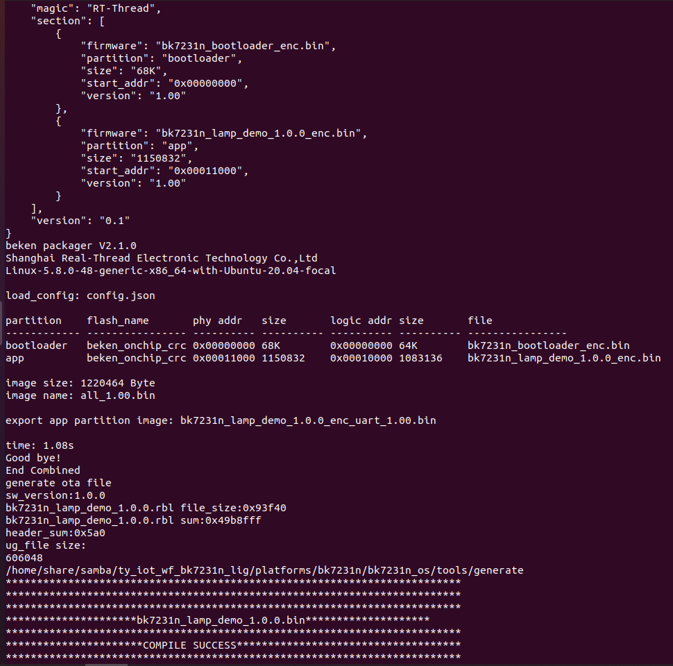
Firmware build and flashing
In Linux terminal, run build_app.sh script to build firmware. The generated firmware is located in apps > APP_PATH > output.
-
Command format:
build_app.sh <APP_PATH> <APP_NAME> <APP_VERSION> -
Sample command:
/home/share/samba/ci/ty_iot_wf_bt_sdk_bk7231t$ sudo sh build_app.sh apps/bk7231t_plant_grow_mach_demo bk7231t_plant_grow_mach_demo 1.0.0 -
The following figures show a successful return.
After flashing firmware to the module, we move to functional debugging. For more information about flashing and authorization, see WB Serial Module Burning and Authorizing.
Step 5: Device control
Install the Tuya Smart app or Smart Life app on your mobile phone. They are available in mobile app markets. Open the app and click the + icon in the top right corner to pair the device. After the device is connected, you can control it with the app.
Summary
Congratulations! You have prototyped a cool desk lamp now. Regarding the sitting position detection, we use the basic approach to achieve it. You can try a radar with a higher frequency or single-input and multiple-output (SIMO) radar to discover more awesome features. Tuya IoT Platform provides convenient IoT development tools and services, which are designed to make your IoT project much easier and efficient. Check it out and discover more awesome ideas.
Is this page helpful?
YesSuggestions


