Prototype a Smart Mirror
Overview
A morning routine can be enhanced with an impressive smart mirror that is ready to feed you whatever information you need at a glance as you get ready to start your day, such as weather, time, local news, and more. Having such a magic mirror is no longer a thing of our imagination. It is from fiction to reality. You can indeed build your own smart mirror rather easily with some tools and know-how. Here is how to make it happen. The mirror is designed to provide three types of light, cool white, natural white, and warm white, which can mimic sunny and overcast lighting conditions. A 4-channel touch key coupled with a PIR sensor ensures a good user experience. We put a wireless charger in the lithium battery-powered smart mirror to enhance its utility value even more. And our ultimate goal is to make it IoT-enabled, so this mirror can be controlled with our mobile phone from anywhere.
Materials
Tuya's Wi-Fi and Bluetooth LE combo module
Count:1A network module enables the mirror to connect to the cloud.more
PCB assembly
Count:1LED driver
Count:1LED bead
Count:8Touchpad
Count:1Screen
Count:1Prepare a screen as you like.
Spring
Count:48 mm × 8 mm × 5 mm × 0.47 mm
XH connector wire
Count:1250 mm 3P and single head tinned.
XH connector wire
Count:2250 mm 4P and dual head with same direction.
XH connector wire
Count:1250 mm 4P with single head tinned.
XH connector wire
Count:1250 mm 7P and dual head with same direction.
Lithium battery
Count:1Wireless charging transmitter and receiver
Count:1Structural channel made by laser engraving
Count:3Structural channel made by 3D printing
Count:6Flat-head self-tapping screw
Count:9M3.5 × 10
Flat-head self-tapping screw
Count:12M2.2 × 8
Jumper wire
Count:1U-shaped and 0.4 to 3 mm
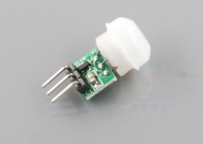
PIR sensor
Count:1Used to detect human motion.
Steps
Step 1: Feature design
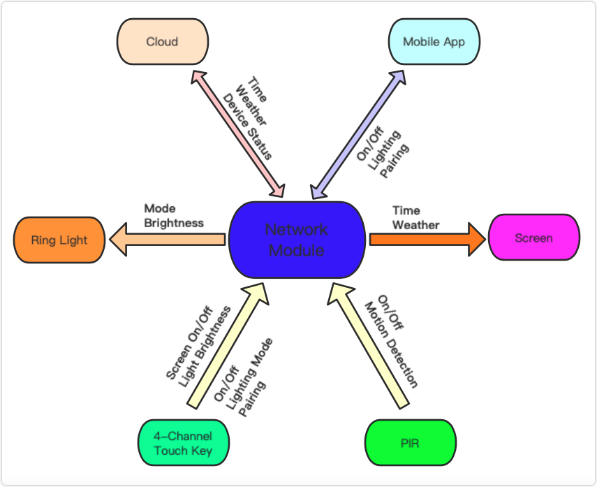
We intend to implement the following features in the smart mirror.
- Information display such as weather and time.
- Three lighting modes: warm white, cool white, and natural white.
- Human motion detection
- 4-channel touch key for on/off, mode switching, brightness up, and brightness down.
- Remote control with the mobile app.
- Powered by lithium battery.
- Wireless charging.
- Self-designed mirror shape.
Then, we figure out how to make these features work, as shown in the following block diagram.
Step 2: Hardware selection
Microcontroller
Use Tuya’s Wi-Fi and Bluetooth LE combo module as the microcontroller. Tuya provides a series of proprietary network modules with various specifications and methods of soldering to address different needs of IoT product development.
Screen
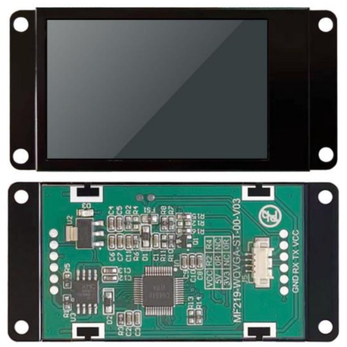
Choose an easy-to-develop screen with a low resource footprint, such as MF219 from Spotpear.
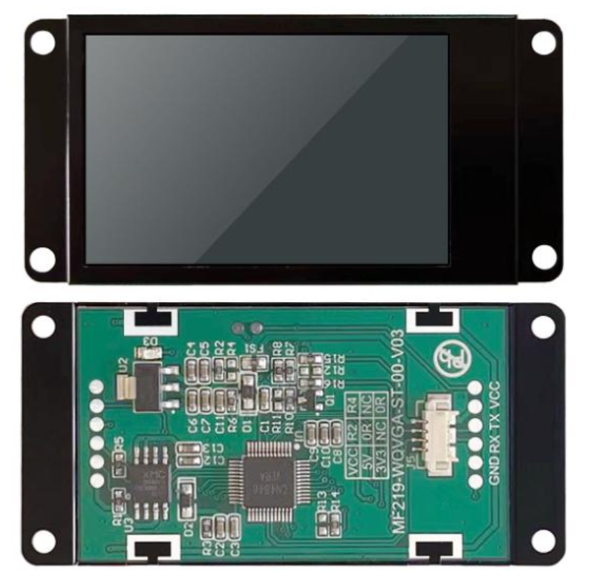
MF219 is a 2.19 inch UART LCD screen with 240 × 376 resolution. It has a built-in ASCII character set and provides access to the dot matrix display data RAM (DDRAM), which allows graphic display at any position on the screen. The UART interface enables serial communication. Developing with the powerful driver, you can design a nice and pretty user interface with a few lines of code. A host of integrated SoC resources and instruction sets make the development much easier.
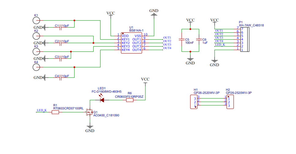
Touch keys
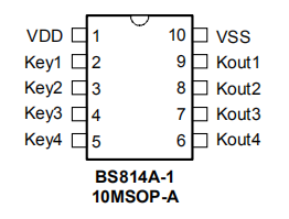
The BS814A-1 touch IC enables touch sensing. The BS81x is a series of ICs with 2 to 16 touch keys. It can detect human body contact using external touchpads. The high level of integration enables applications to be implemented with minimized external components. The BS81x series are equipped with serial or parallel interfaces to allow communication with an external MCU for device setup and for touch pin monitoring purposes. The special internal circuitry is employed to ensure excellent power noise rejection to reduce the possibility of false detections, increasing the application reliability under adverse environmental conditions. With auto-calibration, low standby current, excellent resistance to voltage fluctuation, and other features, this range of touch key ICs can provide a simple and effective approach to touch key operation in a wide variety of applications.
Features
- Operating voltage: 2.2V to 5.5V
- Low standby current
- Auto-calibration
- Reliable touch detections
- Standby and normal operating modes
- Maximum key on duration time detection
- Adaptive voltage drop function
- Level hold: selectable active low or active high
- NMOS output with internal pull-high or CMOS direct output
- Sensitivity adjustment using an external capacitor
- Minimized external components
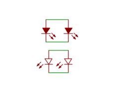
Ring light
A ring light is made with LED drivers and beads, used to create a balanced light distribution and halo shadow on and around its subject.
- HL-AM-2835H489W-S1-08HL-HR3 emits warm white lights.
- HL-AM-2835H421W-S1-08-HR3 emits cool white lights.
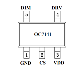
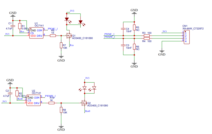
- Use two OC7141 step-down constant current LED drivers to support stepless dimming.
Connect an external resistor and N-channel MOSFET to the OC7141 driver for a constant current circuit so that the output current (10 mA to 3,000 mA) can be controlled by varying the external resistor.
Features
- Power supply voltage: 2.5V to 6V
- Low quiescent current: 60 μA
- Output current: 10 mA to 3,000 mA
- PWM frequency: up to 10 kHz
- Current accuracy: ± 4%
- Over-temperature protection
- The power supply voltage can be extended to more than 400V.
Human motion detection
Use a PIR motion sensor module to detect human activity.
Power supply design
The power supply system in the circuit should support step-down DC/DC regulators, battery, fuel gauging, wireless charging, and cable charging.
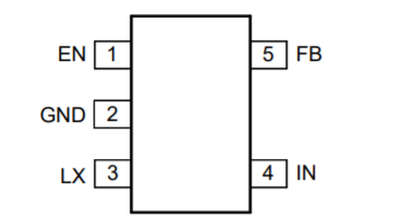
Power supply IC
Use two SY8089A1AAC step-down DC/DC regulators. One regulator steps down the 5V input voltage to 4.35V to charge the lithium battery and the other one steps down the output from the lithium battery to 3.3V to supply the microcontroller, touch keys, ring light, and PIR.
SY8089A1 is a high-efficiency 1.5 MHz synchronous step-down DC/DC regulator capable of delivering up to 2A output current. It can operate over a wide input voltage ranging from 2.5V to 5.5V. Using a battery management IC and buck-boost converter is a better alternative to adopting two regulators.Features
- 2.5V to 5.5V input voltage range
- 50 μA low quiescent current
- Low RDS(on) for internal switches (top/bottom): 130 mΩ/85 mΩ
- High switching frequency of 1.5 MHz and minimized external components
- The inrush current limited by internal soft-start
- Output auto discharge
Battery
Since the ring light consumes a lot of power, we prepare a 2A load network and 6000 mAh (3.8V) lithium-polymer battery.
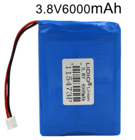
Features
- Rated voltage: 3.8V
- Capacity: 6000 mAH
- Discharge current: 4A
- Cutoff voltage: 2.75V
- Charge current: 0.5C
- Charge limited voltage: 4.35V
- Charge temperature: 0 to 45 °C
- Discharge temperature: -20 to +60°C
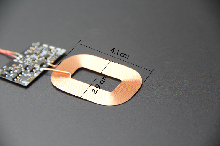
Wireless charging
A wireless charger module consists of a transmitter and a receiver.
Wireless transmitter
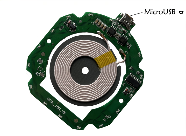
Wireless receiver
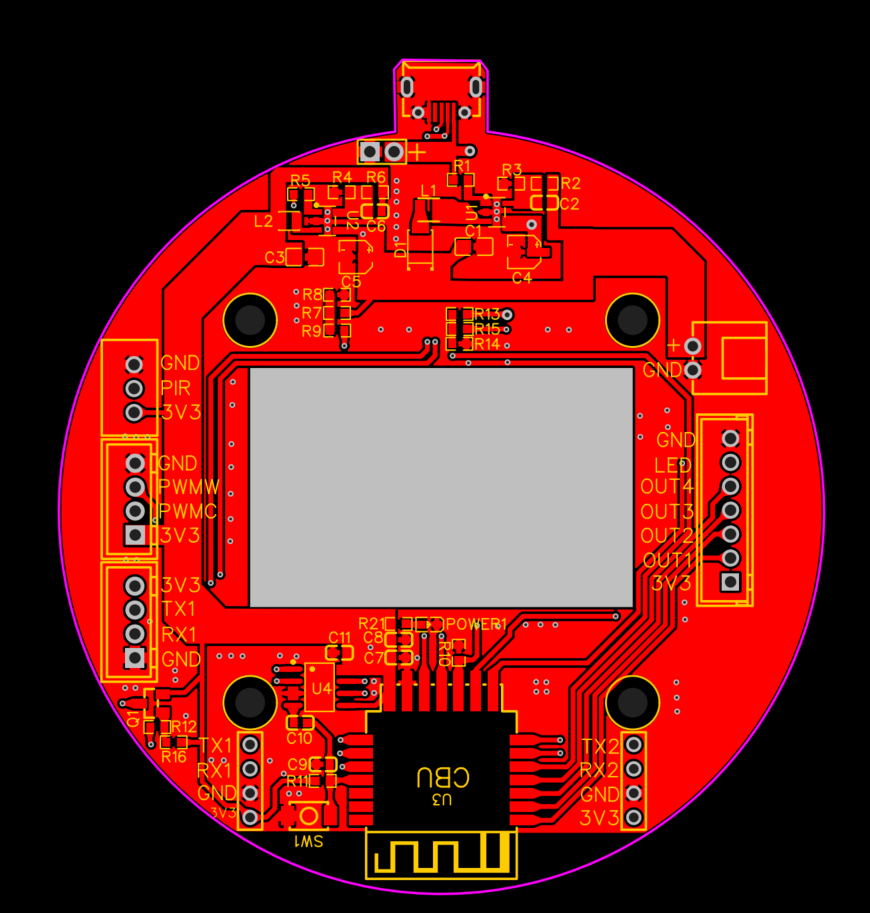
Step 3: Hardware design
We divide the hardware system into three parts: microcontroller and power supply, touch keys and PIR, as well as the ring light, as shown in the following block diagram.

Microcontroller and power supply
This core circuit includes 4.35V DC battery charging, 3.3V DC discharging, microcontroller, USB charger, ADC fuel gauging, screen control, USB bus convert chip, reset circuit, and various interfaces.

Touch keys and PIR
The touch keys and PIR sensor are put in front of the mirror for easy access.
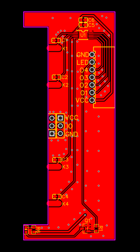
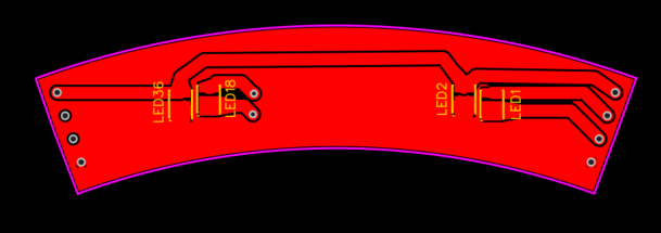
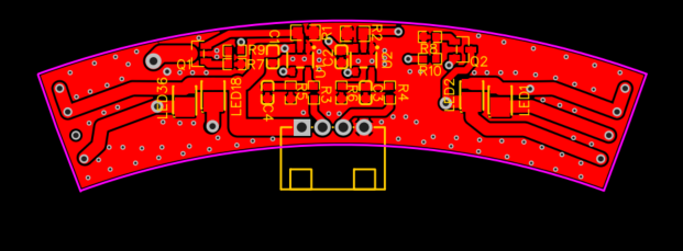
Ring light
The ring light consists of eight LED circuits and one control circuit.
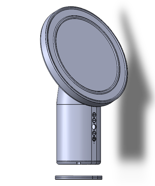
Structural design
The mirror is composed of nine parts: mirror surface, shading board, mirror frame, ring light casing, ring light frame, body, body base, charger cover, and charger base. Download the STL file.
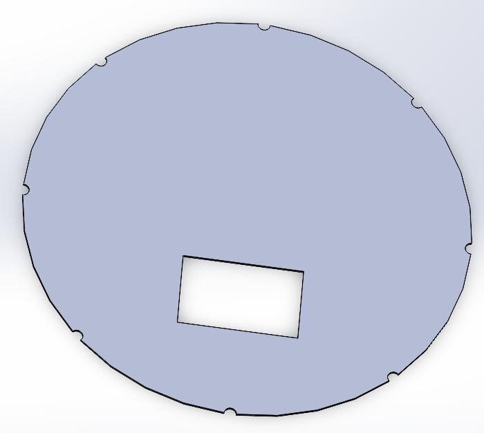
-
Mirror surface

-
Shading board
-
Mirror frame
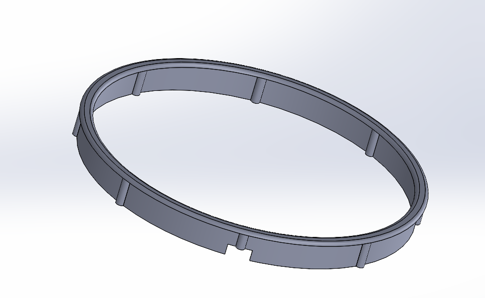
-
Ring light casing
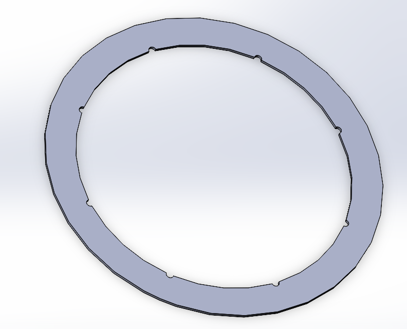
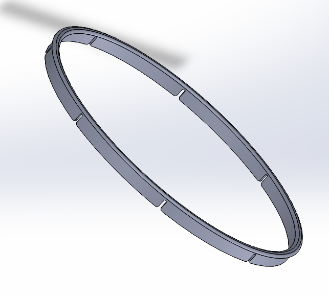
-
Ring light frame
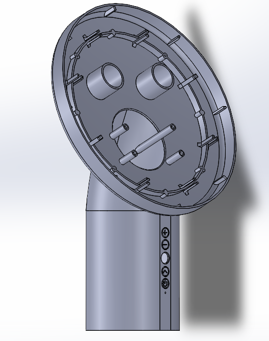
-
Body
-
Body base
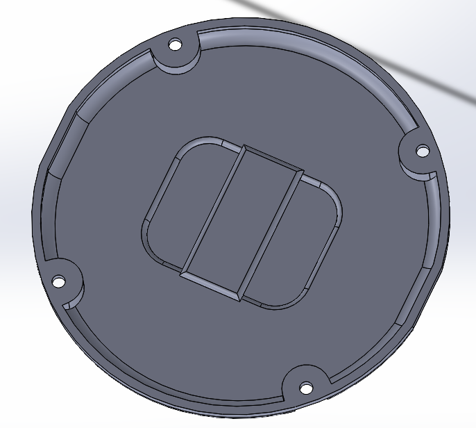
-
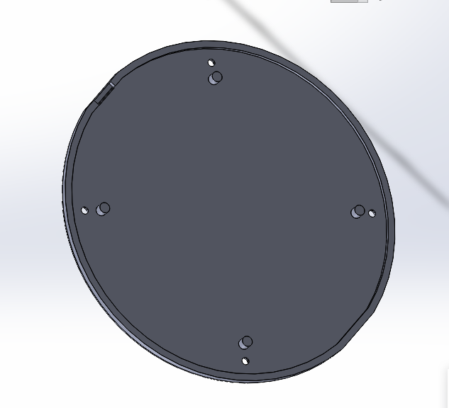
Charger cover
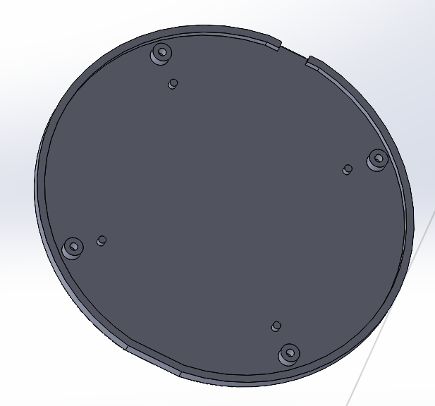
-
Charger base
-
Mirror assembly
-
Exploded-view drawing
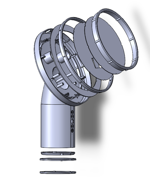
-
Step 4: Product creation
-
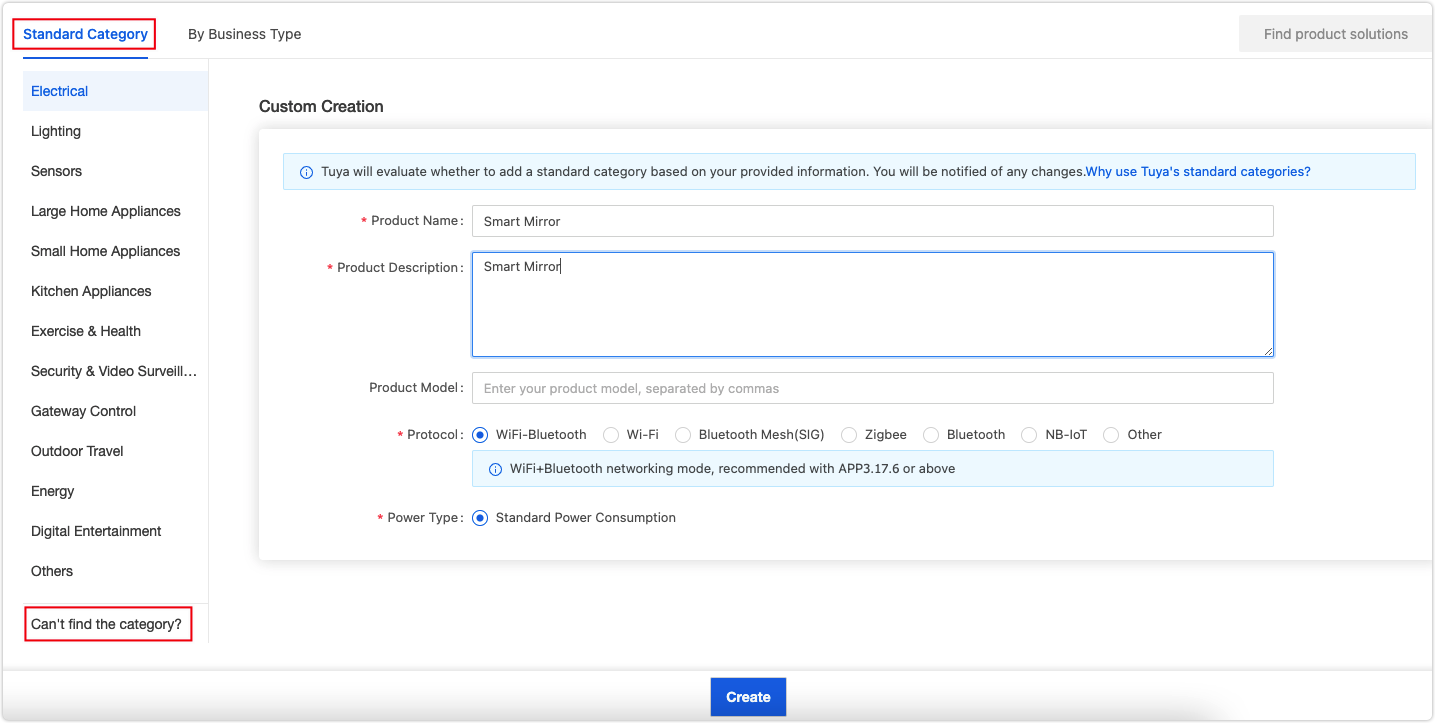
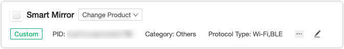
Log in to the Tuya IoT Platform and click the Standard Category tab. Scroll down the page and click Can’t find the category? to create a custom product.
-
Complete the product details, select Wi-Fi-Bluetooth as the protocol, and click Create.
-
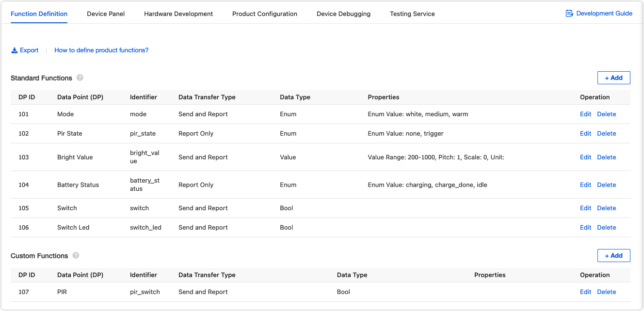
In the step of Function Definition, we add six standard functions, Switch, Switch LED, Mode, Bright Value, Battery Status, and PIR State. We also create a custom function of PIR for PIR on/off control. You can add and create functions as needed, and edit the property for each function.
-
Next, we move to the Device Panel and select a control panel used on the mobile app.
-
In Hardware Development, select an applicable chip platform.
Note: The control panel is available only after you select a chip platform and upload the firmware. The firmware identifier you entered on the Tuya IoT Platform must be consistent with the name of the uploaded firmware. Otherwise, the subsequent firmware flashing will fail.

-
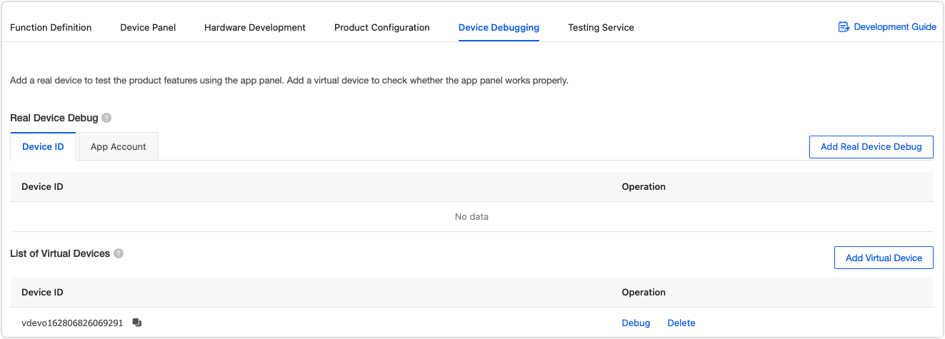
The operation on the platform is completed. You can try the remote control with the virtual device using the Tuya Smart app.
-
Step 5: Embedded development
We proceed with the coding part for these features we want to implement.
Development environment
The microcontroller is built on a BK7231N chip. We run the SDK on Linux. First, set up the Linux development environment and then clone the SDK from GitHub.
-
Download Tuya IoTOS Embedded Wi-Fi & Bluetooth LE SDK.
$ cd "your directory"
$ git clone https://github.com/tuya/tuya-iotos-embeded-sdk-wifi-ble-bk7231n
Download the SDK to your directory and unzip the file. The
appsfolder includes several samples and we usetuya_demo_templateto build an embedded system.
Implement cloud connection
Firstly, we implement the infrastructure for cloud communication. This way, this mirror can communicate with the Tuya IoT Platform.
-
Built on the template
The directory oftuya_demo_templateis as follows.├── src | └── tuya_device.c // Entry file of application layer | ├── include // Header file directory | └── tuya_device.h | └── output // Compiled files -
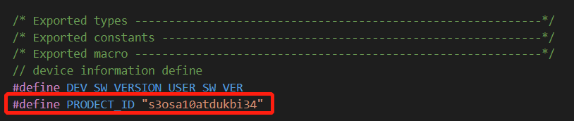
Rename
tuya_demo_templatetobk7231n_mirror_demo. Go toincludeand opentuya_device.h. Change the defined value of macroPRODECT_IDto the product ID (PID) of the product created in Step 4.
-
Create
tuya_app.cas the application code file for this smart mirror project.
The directory we made for this project is as follows.├── src | └── tuya_device.c // Entry file of application layer | └── tuya_app.c // Main application file | ├── include // Header file directory | └── tuya_device.h | └── tuya_app.h | └── output // Compiled files -
tuya_app.hincludes macros for data point (DP) and function declaration for DP data transmission between the mirror and the cloud.#ifndef __TUYA_APP_H__ #define __TUYA_APP_H__ #include "uni_log.h" #include "tuya_cloud_error_code.h" #include "tuya_cloud_com_defs.h" #ifdef __cplusplus extern "C" { #endif /* __cplusplus */ /*********************************************************** *************************variable define******************** ***********************************************************/ typedef enum{ APP_MIRROR_NORMAL, // Normal mode APP_MIRROR_PRODTEST // Product test mode }APP_MIRROR_MODE; #define DPID_SWITCH 1 #define DPID_SWITCH_LED 2 #define DPID_LIGHT_MODE 4 #define DPID_LIGHT_VALUE 5 #define DPID_BATTERY_STATUS 101 #define DPID_PIR_MODE 103 #define DPID_PIR_STATE 105 /******************************************************************************** * FUNCTION: app_mirror_init * DESCRIPTION: application initialization * INPUT: mode:application mode * OUTPUT: none * RETURN: none * OTHERS: none * HISTORY: January 12, 2021 *******************************************************************************/ OPERATE_RET app_mirror_init(IN APP_MIRROR_MODE mode); /******************************************************************************** * FUNCTION: deal_dp_proc * DESCRIPTION: deal the data sented by app * INPUT: root:app issued data structure * OUTPUT: none * RETURN: none * OTHERS: none * HISTORY: January 12, 2021 *******************************************************************************/ VOID deal_dp_proc(IN CONST TY_OBJ_DP_S *root); /********************************************************************************* * FUNCTION: app_report_all_dp_status * DESCRIPTION: report all dp date * INPUT: none * OUTPUT: none * RETURN: none * OTHERS: dp_cnt needs to be modified when adding or deleting the dp function * HISTORY: January 12, 2021 *****************************************************************************/ VOID app_report_all_dp_status(VOID); #ifdef __cplusplus } #endif /* __cplusplus */ #endif /* __TUYA_APP_H__*/ -
In
tuya_app.c, you need to implementdeal_dp_procandapp_report_all_dp_statusto process DP data received from the cloud and DP data sent to the cloud respectively. The SDK can filter the DP data sent to the cloud, so we can implement data sending of all DPs at a time.// Receive DP data from the cloud and parse the DP ID and data content. VOID deal_dp_proc(IN CONST TY_OBJ_DP_S *root) { UCHAR_T dpid; dpid = root->dpid; PR_DEBUG("dpid:%d",dpid); switch (dpid) { case DPID_SWITCH: // Get the DP content. mirror_ctrl_data.Mirror_switch = root->value.dp_bool; break; case DPID_SWITCH_LED: ...... break; case DPID_LIGHT_MODE: ...... break; case DPID_LIGHT_VALUE: ...... break; case DPID_PIR_MODE: ...... break; default: break; } app_report_all_dp_status(); return; } // Report the DP data to the cloud. After the SDK determines the cloud is connected, it reports the data of all DPs. VOID app_report_all_dp_status(VOID) { OPERATE_RET op_ret = OPRT_OK; GW_WIFI_NW_STAT_E wifi_state = 0xFF; op_ret = get_wf_gw_nw_status(&wifi_state); if (OPRT_OK != op_ret) { PR_ERR("get wifi state err"); return; } if (wifi_state <= STAT_AP_STA_DISC || wifi_state == STAT_STA_DISC) { return; } INT_T dp_cnt = 0; dp_cnt = 7; if(!mirror_ctrl_data.Wifi_state) { return; } TY_OBJ_DP_S *dp_arr = (TY_OBJ_DP_S *)Malloc(dp_cnt*SIZEOF(TY_OBJ_DP_S)); if(NULL == dp_arr) { PR_ERR("malloc failed"); return; } memset(dp_arr, 0, dp_cnt*SIZEOF(TY_OBJ_DP_S)); dp_arr[0].dpid = DPID_SWITCH; dp_arr[0].type = PROP_BOOL; dp_arr[0].time_stamp = 0; dp_arr[0].value.dp_value = mirror_ctrl_data.Mirror_switch; dp_arr[1].dpid = DPID_SWITCH_LED; dp_arr[1].type = PROP_BOOL; dp_arr[1].time_stamp = 0; dp_arr[1].value.dp_value = mirror_ctrl_data.Light_switch; dp_arr[2].dpid = DPID_LIGHT_MODE; dp_arr[2].type = PROP_ENUM; dp_arr[2].time_stamp = 0; dp_arr[2].value.dp_value = mirror_ctrl_data.Light_mode; dp_arr[3].dpid = DPID_LIGHT_VALUE; dp_arr[3].type = PROP_VALUE; dp_arr[3].time_stamp = 0; dp_arr[3].value.dp_value = mirror_ctrl_data.Light_value; dp_arr[4].dpid = DPID_BATTERY_STATUS; dp_arr[4].type = PROP_ENUM; dp_arr[4].time_stamp = 0; dp_arr[4].value.dp_value = mirror_ctrl_data.Battery_remain; dp_arr[5].dpid = DPID_PIR_MODE; dp_arr[5].type = PROP_BOOL; dp_arr[5].time_stamp = 0; dp_arr[5].value.dp_value = mirror_ctrl_data.PIR_switch; dp_arr[6].dpid = DPID_PIR_STATE; dp_arr[6].type = PROP_ENUM; dp_arr[6].time_stamp = 0; dp_arr[6].value.dp_value = mirror_ctrl_data.PIR_state; op_ret = dev_report_dp_json_async(NULL,dp_arr,dp_cnt); Free(dp_arr); if(OPRT_OK != op_ret) { PR_ERR("dev_report_dp_json_async relay_config data error,err_num",op_ret); } PR_DEBUG("dp_query report_all_dp_data"); return; } -
Edit callbacks in
tuya_device.cfor the implemented functionsdeal_dp_procandapp_report_all_dp_status.VOID dev_obj_dp_cb(IN CONST TY_RECV_OBJ_DP_S *dp) { PR_DEBUG("dp->cid:%s dp->dps_cnt:%d",dp->cid,dp->dps_cnt); UCHAR_T i = 0; for(i = 0;i < dp->dps_cnt;i++) { deal_dp_proc(&(dp->dps[i])); dev_report_dp_json_async(get_gw_cntl()->gw_if.id, dp->dps, dp->dps_cnt); } } VOID hw_report_all_dp_status(VOID) { app_report_all_dp_status(); } STATIC VOID dev_dp_query_cb(IN CONST TY_DP_QUERY_S *dp_qry) { PR_NOTICE("Recv DP Query Cmd"); hw_report_all_dp_status(); }
The infrastructure for the communication between the mirror and the cloud is completed. You can print logs to test the communication.
Sample code for the smart mirror
Entry to application
Download the demo routine. The
appsfolder contains the application code for the mirror. The directory of the application code is as follows:├── src | ├── mirror_driver | | ├── tuya_mirror_pwm.c // PWM driver | | ├── tuya_mirror_key.c // Code for touch keys | | └── tuya_mirror_screen.c // Code for the display | ├── mirror_soc // Code for interfaces of the SoC | ├── tuya_device.c // Entry file of the application layer | ├── tuya_app.c // Main application | ├── svc_weather_service.c // Weather service components (not public-facing now) | └── tuya_mirror_control.c // Logic for device features | ├── include // Header file directory | ├── mirror_driver | | ├── tuya_mirror_pwm.h | | ├── tuya_mirror_key.h | | └── tuya_mirror_screen.h | ├── mirror_soc | ├── tuya_device.h | ├── tuya_app.h | ├── svc_weather_service.h | └── tuya_mirror_control.h | └── output // Compiled filesOpen
tuya_device.cand find thedevice_initfunction.OPERATE_RET device_init(VOID_T) { OPERATE_RET op_ret = OPRT_OK; TY_IOT_CBS_S wf_cbs = { status_changed_cb,\ gw_ug_inform_cb,\ gw_reset_cb,\ dev_obj_dp_cb,\ dev_raw_dp_cb,\ dev_dp_query_cb,\ NULL, }; op_ret = tuya_iot_wf_soc_dev_init_param(WIFI_WORK_MODE_SEL, WF_START_SMART_ONLY, &wf_cbs, NULL, PRODECT_ID, DEV_SW_VERSION); if(OPRT_OK != op_ret) { PR_ERR("tuya_iot_wf_soc_dev_init_param error,err_num:%d",op_ret); return op_ret; } op_ret = tuya_iot_reg_get_wf_nw_stat_cb(wf_nw_status_cb); if(OPRT_OK != op_ret) { PR_ERR("tuya_iot_reg_get_wf_nw_stat_cb is error,err_num:%d",op_ret); return op_ret; } op_ret = app_mirror_init(APP_MIRROR_NORMAL); if(OPRT_OK != op_ret) { PR_ERR("app init err!"); return op_ret; } return op_ret; }In the development environment for the BK7231N chip, the
device_initfunction is the entry to the application code. When a device is powered on, it calls the application initialization function after the hardware is initialized.This function deals with the following:
-
Calls
tuya_iot_wf_soc_dev_init_param()for SDK initialization to configure working mode and pairing mode of the SoC, register callbacks, and save the PID. The macro for PID isPRODECT_KEYin the code.TY_IOT_CBS_S wf_cbs = { status_changed_cb,\ gw_ug_inform_cb,\ gw_reset_cb,\ dev_obj_dp_cb,\ dev_raw_dp_cb,\ dev_dp_query_cb,\ NULL, }; op_ret = tuya_iot_wf_soc_dev_init_param(WIFI_WORK_MODE_SEL, WF_START_SMART_FIRST, &wf_cbs, NULL, PRODECT_ID, DEV_SW_VERSION); if(OPRT_OK != op_ret) { PR_ERR("tuya_iot_wf_soc_dev_init_param error,err_num:%d",op_ret); return op_ret; } -
Call
tuya_iot_reg_get_wf_nw_stat_cb()to register the callback for device network status.op_ret = tuya_iot_reg_get_wf_nw_stat_cb(wf_nw_status_cb); if(OPRT_OK != op_ret) { PR_ERR("tuya_iot_reg_get_wf_nw_stat_cb is error,err_num:%d",op_ret); return op_ret; } -
Call the application initialization function.
    op_ret = app_mirror_init(APP_MIRROR_NORMAL);
    if(OPRT_OK != op_ret) {
        PR_ERR("app init err!");
        return op_ret;
    }
The application initialization function
app_mirror_initis implemented intuya_app.c. A thread can be created to run the application code upon entry intoapp_mirror_init.Application initialization
When
app_mirror_initintuya_app.cis called, the program reads the device data in the flash memory, then callsmirror_device_initto initialize applications, and finally creates a thread for each feature.OPERATE_RET app_mirror_init(IN APP_MIRROR_MODE mode) { OPERATE_RET op_ret = OPRT_OK; if(APP_MIRROR_NORMAL == mode) { UCHAR_T read_buff[SAVE_DATA_LEN] = {0}; uiSocFlashRead(APP_DATA_SAVE,APP_DATA_SAVE_OFFSET,SAVE_DATA_LEN,read_buff); mirror_data_load(read_buff); UCHAR_T i = 0; for(i = 0;i < SAVE_DATA_LEN;i++){ PR_NOTICE("------- readbuff = %d -----",read_buff[i]); } mirror_device_init(); tuya_hal_thread_create(NULL, "thread_data_get", 512*8, TRD_PRIO_4, sensor_data_get_thread, NULL); tuya_hal_thread_create(NULL, "thread_data_deal", 512*4, TRD_PRIO_4, sensor_data_deal_thread, NULL); tuya_hal_thread_create(NULL, "key_scan_thread", 512*4, TRD_PRIO_3, key_scan_thread, NULL); tuya_hal_thread_create(NULL, "diplay_send_thread", 512*4, TRD_PRIO_3, diplay_send_thread, NULL); }else { //not factory test mode } return op_ret; }Implement the handle for each thread. The function called in the handle is in
mirror.control.c.#define TASKDELAY_SEC 1000 STATIC VOID sensor_data_get_thread(PVOID_T pArg) { while(1) { mirror_data_get_handle(); tuya_hal_system_sleep(TASKDELAY_SEC); } } STATIC VOID diplay_send_thread(PVOID_T pArg) { while(1) { tuya_hal_system_sleep(TASKDELAY_SEC/2); mirror_display_poll(); } } STATIC VOID key_scan_thread(PVOID_T pArg) { while(1) { mirror_key_poll(); tuya_hal_system_sleep(25); } } STATIC VOID sensor_data_deal_thread(PVOID_T pArg) { while(1) { tuya_hal_system_sleep(TASKDELAY_SEC/2); if(mirror_ctrl_data.Wifi_state == connecting) { mirror_wifi_light_handle(); }else { mirror_ctrl_handle(); } } }
Touch keys
app_key_init()andapp_key_scan()are included intuya_mirror_key.c.app_key_init()is used to initialize the I/O of touch keys.app_key_scan()is used to scan keypress events and get the key value.void app_key_scan(unsigned char *trg,unsigned char *cont) { unsigned char read_data; if(KEY_RELEAS_LEVEL) { read_data = 0x0F; }else { read_data = 0x00; } read_data = (tuya_gpio_read(KEY_SWITCH_PIN)<<3)|(tuya_gpio_read(KEY_SET_PIN)<<2)|(tuya_gpio_read(KEY_UP_PIN)<<1)|(tuya_gpio_read(KEY_DOWN_PIN)); *trg = (read_data & (read_data ^ (*cont))); *cont = read_data; }This function detects keypress events and passes the key value to two parameters.
trgrepresents the key value when a key is triggered.contrepresents the key value when a key is released. This way, we can implement keypress events including press, press and hold, and composite key.key_scan_threadis one of the application thread handles.app_key_scanintuya_mirror_control.cis called in this handle to scan a keypress event. The thread sleep time is the scanning interval.VOID mirror_key_poll(VOID) { MIRROR_CTRL_DATA_T *p; p = &mirror_ctrl_data; app_key_scan(&key_trg,&key_cont); switch (key_cont) { case KEY_CODE_RELEASE: if(key_buf != 0) { mirror_key_event(key_buf); } key_buf = 0; key_old = KEY_CODE_RELEASE; break; case KEY_CODE_SWITCH: vTaskDelay(10); app_key_scan(&key_trg,&key_cont); if(key_cont == KEY_CODE_SWITCH) { key_buf = KEY_CODE_SWITCH; } key_old = KEY_CODE_SWITCH; break; case KEY_CODE_SET_LIGHT_COLOR: if(key_old == KEY_CODE_SET_LIGHT_COLOR) { key_delay_cont++; }else{ key_delay_cont = 0; } if(key_delay_cont >= 2) { key_buf = KEY_CODE_SET_LIGHT_COLOR; } if(key_delay_cont >= 200) { key_buf = 0; key_delay_cont = 0; tuya_iot_wf_gw_unactive(); // start connect; } key_old = KEY_CODE_SET_LIGHT_COLOR; break; case KEY_CODE_UP: if(p->Mirror_switch == FALSE) { key_buf = 0; return ; } if(p->Light_switch == FALSE) { key_buf = 0; return ; } if(key_old == KEY_CODE_UP) { key_delay_cont++; }else{ key_delay_cont = 0; } if(key_delay_cont >= 2) { key_buf = KEY_CODE_UP; } if(key_delay_cont >= 40) { key_buf = 0; if(p->Light_value <= 995) { p->Light_value += 10; mirror_pwm_set(p->Light_mode,p->Light_value); } } key_old = KEY_CODE_UP; break; case KEY_CODE_DOWN: if(p->Mirror_switch == FALSE) { key_buf = 0; return ; } if(p->Light_switch == FALSE) { key_buf = 0; return ; } if(key_old == KEY_CODE_DOWN) { key_delay_cont++; }else{ key_delay_cont = 0; } if(key_delay_cont >= 2) { key_buf = KEY_CODE_DOWN; } if(key_delay_cont >= 40) { key_buf = 0; if(p->Light_value>=205) { p->Light_value -= 10; mirror_pwm_set(p->Light_mode,p->Light_value); } } key_old = KEY_CODE_DOWN; break; default: break; } }When
app_key_scan()scans an event and gets the key value, the specified command is executed accordingly. This way, the touch key feature is implemented.Screen display
We use a 2.19 inch UART LCD screen with 240 × 376 resolution, which is easy to develop with the communication protocol. We collect some image icons as per the screen resolution to have a nice display of weather, date, battery level, and more.
These collected icons are compressed into a
.binfile and written into the screen chip.tuya_mirror_screen.cincludes screen initialization functionscreen_init()and functions for information display, namelyscreen_display_time(),screen_display_week(),screen_display_year(), andscreen_display_day. When these functions are called in the application thread, the fetched local time and date is passed in for display.VOID screen_init(VOID); VOID screen_display_time(INT_T hours, INT_T mins); VOID screen_display_week(INT_T weeks); VOID screen_display_year(INT_T year); VOID screen_display_battery(BATTERY_STATE state); VOID screen_display_day(INT_T month, INT_T day);Icons are stored in the flash memory. To display an icon, a string containing the icon address, icon dimension, and display position is sent to the screen chip. You can save strings of all addresses to an array to save retrieval time.
UINT8_T *icon_buff[] = {
   /* 0 ~ 9 and ':' */
   "2289100","2290660","2292220","2293780","2295340","2296900","2298460","2300020","2301580","2303140","2305600",

     /* character: 'Month', 'Day', 'Year' (11 to 13) */
   "2312464","2314264","2316064",

     /* character: 'Sunday' to 'Saturday' (14 to 20) */
   "2349832","2317864","2323192","2328520","2333848","2339176","2344504",

   /* '℃' and white block (21~22)*/
   "2386480","2387560",

     /* Icon of condition: sun, rain, and cloud (23 to 25)*/

   "2241228","2249420","2258520",

     /* Character of condition: sun, rain, and cloud (26 to 28)*/
   "2267620","2272380","2277140",

     /* Icon of battery: high, medium, low, and charging (29 to 32)*/
   "2355160","2362990","2370820","2378650",
};
Take the date display as an example. Retrieve the array based on the parameter, get the icon address, make a complete string, and send this string to the screen chip for display.
VOID screen_display_week(INT_T weeks)
{
 if((weeks < 0)||(weeks > 6)) {
     return;
 }

 uint8_t data_buff[40] = {0};

 snprintf(data_buff,sizeof(data_buff),"FSIMG(%s,280,95,72,37,0);\r\n",icon_buff[weeks+14]);

 tuya_uart_write(uart0, data_buff, strlen(data_buff));
}
The implement of displaying other elements works the same way.
Get time and date
Make an API request through the SDK to get the local time after the mirror is connected to the cloud.
To get the local time, you must include the header file
uni_time.h. Define a struct variable of the local time. Pass it as a parameter and calluni_local_time_get()to get the local time.STATIC VOID mirror_date_get(VOID) { if(mirror_ctrl_data.Wifi_state == connecting) { return; } POSIX_TM_S cur_time; if( uni_local_time_get(&cur_time) != OPRT_OK ) { PR_NOTICE("cant get local time"); } mirror_ctrl_data.Mirror_time.sec = (UCHAR_T)cur_time.tm_sec; mirror_ctrl_data.Mirror_time.min = (UCHAR_T)cur_time.tm_min; mirror_ctrl_data.Mirror_time.hour = (UCHAR_T)cur_time.tm_hour; if(mirror_ctrl_data.Mirror_time.year != cur_time.tm_year) { mirror_ctrl_data.Mirror_time.year = (1900 + cur_time.tm_year); } if((mirror_ctrl_data.Mirror_time.mon != cur_time.tm_mon)||(mirror_ctrl_data.Mirror_time.mday != cur_time.tm_mday)) { mirror_ctrl_data.Mirror_time.mon= (UCHAR_T)cur_time.tm_mon; mirror_ctrl_data.Mirror_time.mday = (UCHAR_T)cur_time.tm_mday; } if(mirror_ctrl_data.Mirror_time.wday != cur_time.tm_wday) { mirror_ctrl_data.Mirror_time.wday = (UCHAR_T)cur_time.tm_wday; } }Note that the year starts with 1900. For example, if you get
cur_time.tm_year == 121, it indicates the year 2021. Then, feed the fetched time and date to the display function. You will see the expected information display on the screen.PWM driver
The 2-channel PWM driver enables brightness adjustment and light color changing for the cool white and warm white LED beads.
tuya_mirror_pwm.cincludes code for PWM initialization and startup and duty cycle configuration.OPERATE_RET mirror_pwm_init(VOID); OPERATE_RET mirror_pwm_set(UCHAR_T color, USHORT_T duty); OPERATE_RET mirror_pwm_off(VOID);mirror_pwm_set()can enable and disable the 2-channel PWM output and set the duty cycle. You can input the light color parameter and duty cycle to switch between cool white and warm white and adjust brightness.OPERATE_RET mirror_pwm_set(UCHAR_T color, USHORT_T duty) { FLOAT_T percent = 0.0; if(user_pwm_init_flag != TRUE){ PR_ERR("user pwm not init!"); return OPRT_INVALID_PARM; } percent = (FLOAT_T)(duty/1000.0); bk_pwm_stop(pChannelList[0]); bk_pwm_stop(pChannelList[1]); switch (color) { case 0: PR_NOTICE("set light cold"); bk_pwm_update_param(pChannelList[0], pwm_period, (UINT32)(percent * pwm_period), 0, 0); bk_pwm_start(pChannelList[0]); break; case 1: PR_NOTICE("set light medium"); bk_pwm_update_param(pChannelList[0], pwm_period, (UINT32)((percent * pwm_period)/2), 0, 0); bk_pwm_update_param(pChannelList[1], pwm_period, (UINT32)((percent * pwm_period)/2), 0, 0); bk_pwm_start(pChannelList[0]); bk_pwm_start(pChannelList[1]); break; case 2: PR_NOTICE("set light warm"); bk_pwm_update_param(pChannelList[1], pwm_period, (UINT32)(percent * pwm_period), 0, 0); //bk_pwm_update_param(pChannelList[0], pwm_period, 0, 0, 0); bk_pwm_start(pChannelList[1]); break; default: break; } return OPRT_OK; }The implemented functions are called in the application code to achieve light control.
Human motion detection
We implement motion-activated light and screen on/off with a PIR sensor. This sensor outputs high when motion is detected.
Write a function to read the PIR I/O level, which is scheduled to run in the thread. When a high level is read, the PIR status will be saved to the device data struct.
STATIC VOID mirror_pir_detect(VOID)
{
    if(tuya_gpio_read(PIR_IN_PORT)) {
        PR_NOTICE("-----------SOMEONE HERE-------------");
        mirror_ctrl_data.PIR_state = trigger;
    }
}

VOID mirror_data_get_handle(VOID)
{
 	......
 	 // Detect PIR I/O port
 	mirror_pir_detect();
}
STATIC VOID sensor_data_get_thread(PVOID_T pArg) { while(1) { mirror_data_get_handle(); tuya_hal_system_sleep(TASKDELAY_SEC); } }The other thread determines the PIR status. If motion sensing is enabled and the mirror is turned on, a detected motion will trigger turning on the ring light and the timer. As the timer interrupt is triggered, the light will be turned off.
VOID pir_data_handle(VOID)
{
 MIRROR_CTRL_DATA_T *p;

 p = &mirror_ctrl_data;

 if(p->PIR_state == trigger) {
     p->PIR_state = none;

     if((p->PIR_switch != TRUE)||(p->Mirror_switch != TRUE)) {

         return;
     }

     if(IsThisSysTimerRun(off_timer) == TRUE) {
         sys_stop_timer(off_timer);
         sys_start_timer(off_timer, 1000*600, TIMER_ONCE);
     }else {
         sys_start_timer(off_timer, 1000*600, TIMER_ONCE);
     }

     p->Light_switch = TRUE;

 }
}
This way, motion-activated light on and delay light off is made.
Battery level
We use an ADC to read the battery voltage and get the estimated battery level. Based on this, you can display the matched battery level icon on the screen.
After all the required features and cloud communication are implemented, the code for an IoT-enabled mirror is done. Next, download the code to the board.Compile and flash
Run the script
build_app.shincluded in the SDK on the Linux terminal to compile the code. The command takes the format: sh build_app.sh APP_PATH APP_NAME APP_VERSION:
The following figures show a successful compilation.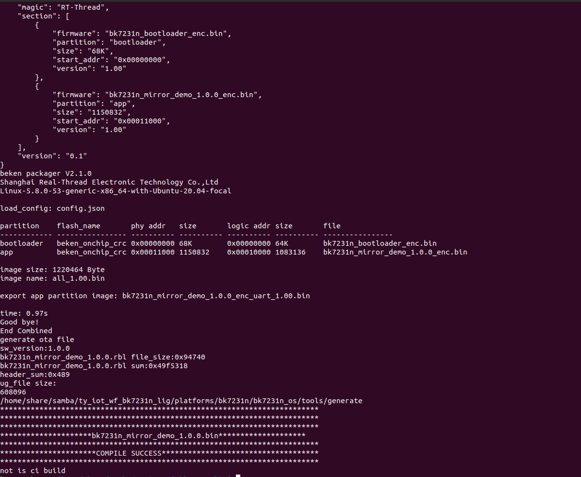
The compiled file is located in
apps>APP_PATH>output.For more information about firmware flashing and authorization, see Flash Firmware to and Authorize WB Series Modules.
-
Summary
Congratulations! A magic mirror is made perfectly. Tuya IoT Platform provides convenient IoT development tools and services, which are designed to make your IoT projects much easier and more efficient. Check it out and discover more awesome ideas.
Is this page helpful?
YesSuggestions


