Prototype a Smart Neck Massager

Overview
Whether it’s from sleeping weirdly, playing too much with your mobile phone, or sitting hunched over for hours staring at your computer, most of us have dealt with kinks in our necks from time to time. One of the best ways to soothe aches and pains in your neck is through massage therapy. Therefore, we retrofit a traditional neck massager and make it smart to melt stress away with ease.
Combining a variety of massage techniques in traditional Chinese physical therapy, the neck relax massager adopts the low-frequency electrical pulse technology to simulate real human massage. It can promote local blood circulation and effectively relieve neck fatigue and muscle tension. Since we have made this massager IoT-enabled, we can control it with just a mobile phone.
Features
-
Five modes: smart, relax, active, tapping, and scraping. Different modes allow you to experience different massage pleasures.
-
15-level intensity from weak to strong: You can freely adjust the intensity suitable for you.
-
3-level temperature adjustment: High, low, and off. Constant heat massage can relax the blood vessels and neck muscles.
Hardware
Materials
BTU network module
Count:1A Bluetooth Low Energy module for connecting a device to the cloud.more
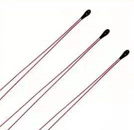
NTC thermistor (MF52B)
Count:1NTC thermistor is epoxy resin-coated in small size, used for temperature measurement. It features a wide range of resistance, high precision stability and sensitivity, as well as fast response.
Heating wire
Count:1Used to conduct heat to support thermostat heating feature.
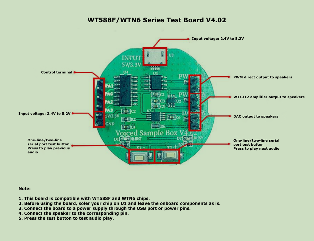
WTN6 voice chip
Count:1In one-line serial port mode, the BTU module can control and send data to the voice chip through the DATA line to have voice play, stop, loop, and more.
Electrode pad
Count:1Two stainless steel electrode pads on the massager.
Rechargeable battery
Count:1We bought a 700 mAh lithium polymer battery with a 3.7V rated voltage and 4.2V charging voltage. It has built-in protection circuit to prevents overcharge, over-discharge, over-current, and short circuit.
Steps
Step 1: Hardware design
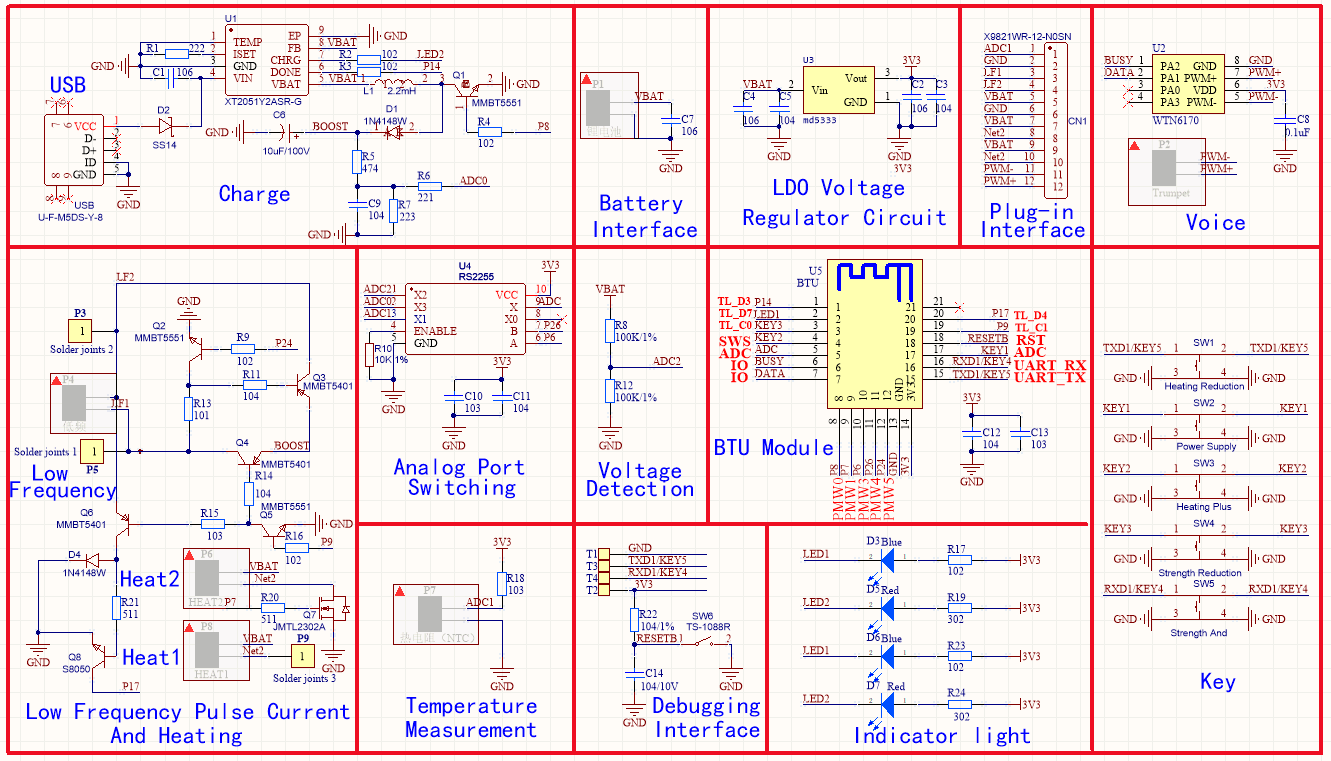
To achieve remote control with the Tuya Smart or Smart Life app, we use Tuya’s BTU network module as the microcontroller.
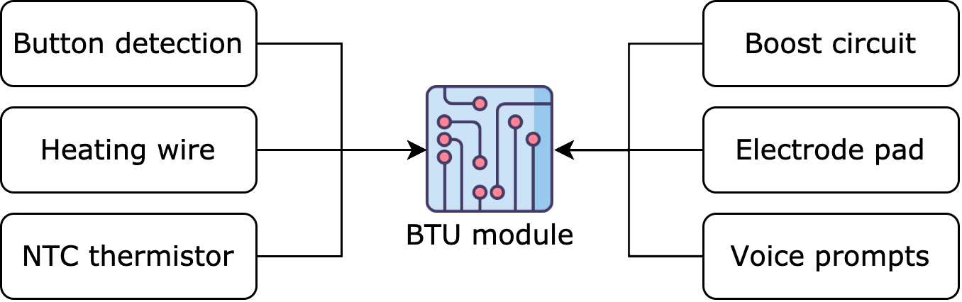
The circuit consists of a BTU module, battery charging, voice play, button detection, low-frequency pulse current output, heating, and temperature detection.
1. Microcontroller
2. Feature modules
-
NTC thermistor (MF52B)
NTC thermistor is epoxy resin-coated in small size, used for temperature measurement. It features a wide range of resistance, high precision stability and sensitivity, as well as fast response. For the parameters of the thermistor, we use: B=3950, R=10k.
The relation between temperature and resistance
Temperature detection circuit
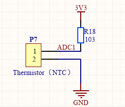
The module’s ADC collects voltage and converts it to a temperature value. Then, the module adjusts the temperature accordingly.
-
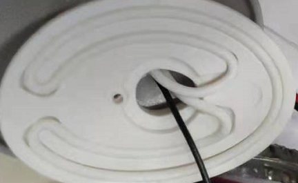
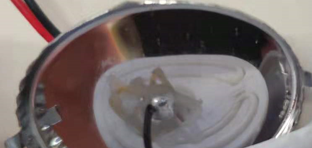
Heating wire
The white wire is the heating wire.
Heating circuit
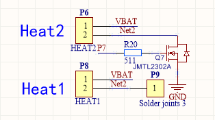
P7 on the module outputs PWM waves to adjust the temperature of the heating wire. When P7 outputs low, heating is off. When P7 outputs square waves at some frequency, heating is at a low level. When P7 outputs high, heating is at a high level.
-
Speaker
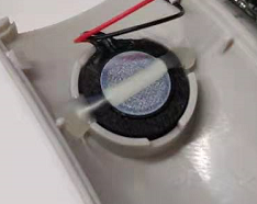
Voice control circuit
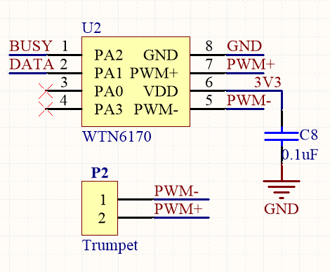
In one-line serial port mode, the BTU module can control and send data to the voice chip through the DATA line to have voice play, stop, loop, and more.
-
Electrode pad
Two stainless steel electrode pads on the massager.
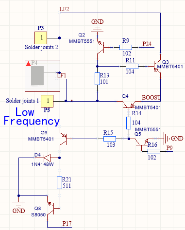
Low-frequency pulse current output
-
The pulses output from P24 and P9 are symmetric. These two pins must not output high at the same time.
-
When P24 outputs high and P9 outputs low, Q2 is on-state and Q5 is cut-off. Q4, Q6, and Q8 are cut-off and Q3 is in saturation (on-state) due to the impedance of the human body.
P17 outputs high. It outputs two low-frequency symmetric pulses.
-
When P24 outputs low and P9 outputs high, Q2 is cut-off and Q5 is on-state. Q4, Q6, and Q8 are on-state and Q3 is cut-off.
P17 outputs low. It outputs two low-frequency symmetric pulses.
-
-
The pulses output from P24 and P9 are asymmetric. PB5 and PCO both output high.
-
When Q5, Q2, and Q6 are on-state, Q4 and Q3 are on-state. This way, the triode might be burned out.
-
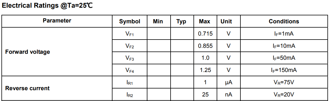
S8050 transistor on/off depends on the voltage on the positive end of the diode D4 that is determined by the current through the diode. Therefore, we can provide overcurrent protection. Once the current through the diode D4 exceeds 10 mA, the voltage drop of D4 will exceed 0.7V and the triode Q2 will be on-state.
-
P24 and P9 on the module can output pulse signals of different frequencies (the pulses output from P24 and P9 are symmetric) and produce different waveforms for various modes.
-
Parameters of diode D4
-
-
Battery
We bought a 700 mAh lithium polymer battery with a 3.7V rated voltage and 4.2V charging voltage. It has a built-in protection circuit to prevents overcharge, over-discharge, over-current, and short circuit.
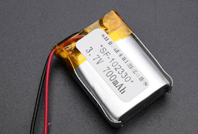
Dimension: 10 mm (thickness) x 23 mm (width) x 30 mm (length)
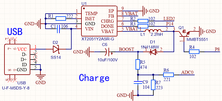
Battery charger circuit and boost circuit
-
Battery charger circuit: The XT2051 is a constant-current and constant-voltage charger circuit for single-cell lithium-ion batteries. The component includes an internal power transistor and does not need an external current sense resistor and blocking diode. XT2051 requires minimal external components and meets the USB bus specification. It is very suitable for portable applications in the field.
-
The principle of boost circuit: When the transistor MMBT5551 is switched on, the Schottky diode D1 is in reverse bias. The current through the inductor L1 to transistor Q1 completes an electrical circuit. The input voltage applied to the boost inductor is converted into magnetic energy for storage. When the transistor Q1 is switched off, the Schottky diode D1 is in forward bias, the magnetic energy in the inductor is transformed into electrical energy. This voltage together with the input voltage supplies power to the load and charges the output capacitor C6. Several pulses are required for enough energy supply to increase the output voltage.
-
Step 2: Create a product
This section describes how to create a smart neck massager on the Tuya IoT Platform. For more information, see Create Products.
-
Log in to the Tuya IoT Platform.
-
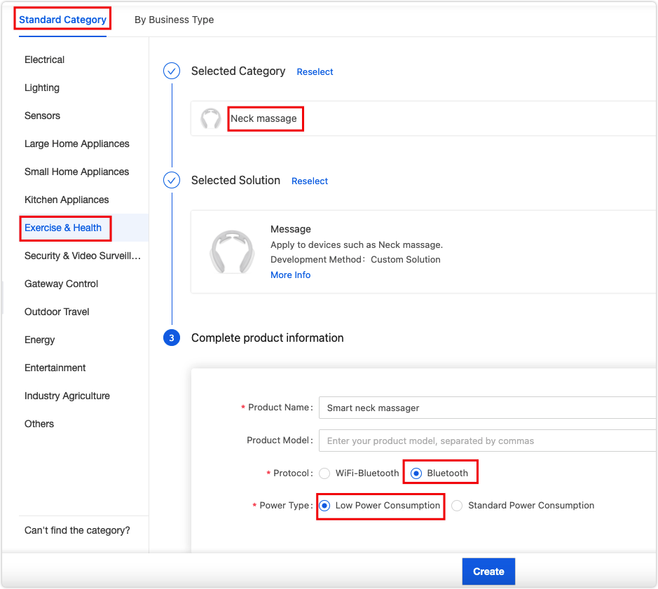
On the Standard Category tab, click Exercise & Health > Exercise & Health. Complete the product information and select Bluetooth as the protocol.
-
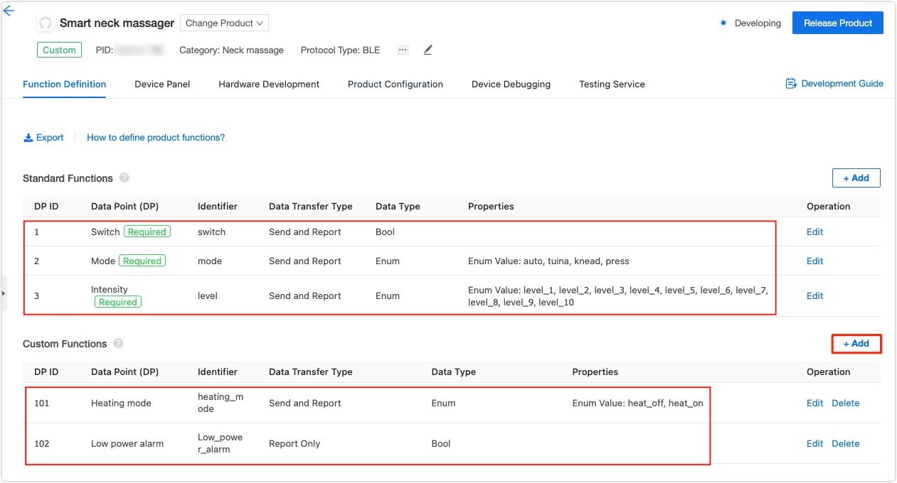
After you click Create, a Add Standard Function dialog box appears. Leave the three selected required functions as is. In the Custom Functions section, click Add and create two functions. For the items to be set, see the screenshot below.
-
In the step of Device Panel, select the DIY Style Panel. Then, go to Hardware Development and select Tuya Standard Module SDK and the BT3L Bluetooth Module. Click Get 10 Free Licenses on the right side of the screen. You will get the UUID, key, and MAC address in coding.

Step 3: Get the SDK and set up IDE
-
GitHub repo
Clone this repo tuya_ble_sdk_Demo_Project_tlsr8253 to your local computer and check out the
README.md. -
Set up IDE
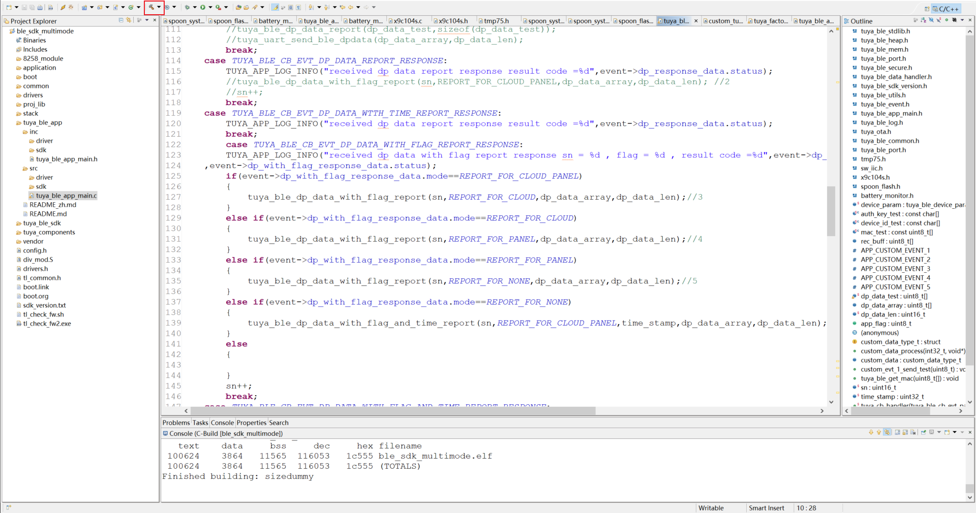
The chip on the module is TLSR825x so we use Telink IDE for development. Go IDE for TLSR8 Chips and download the IDE and check out the project import guide.
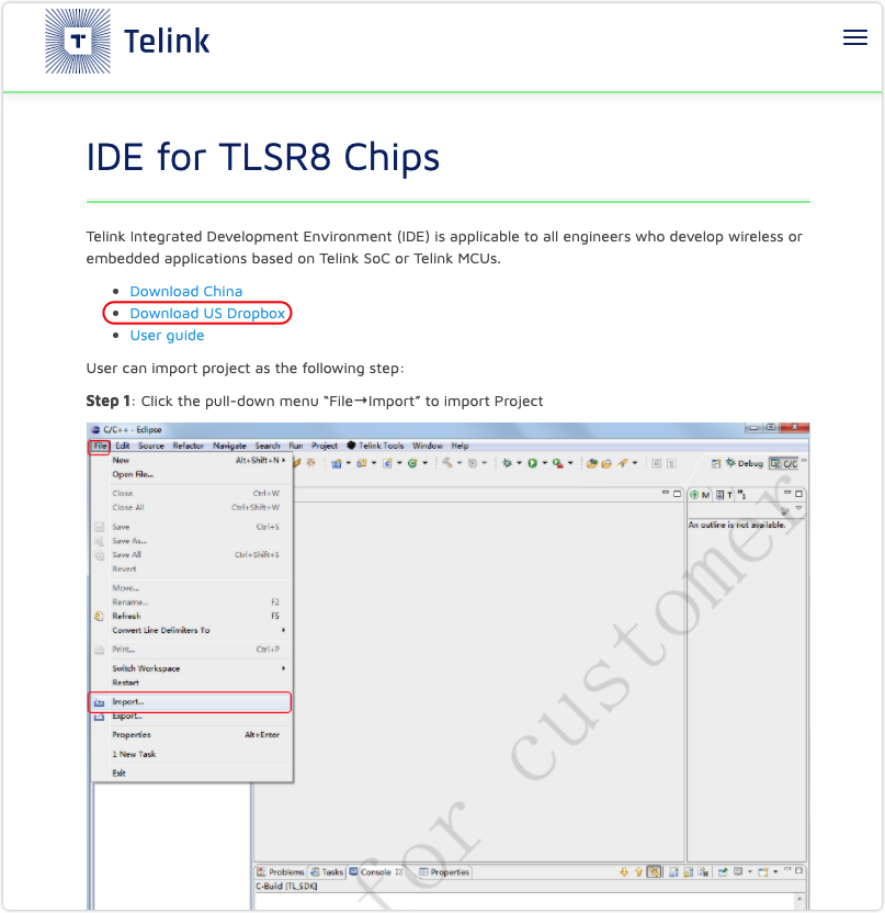
After you have the IDE installed, import your project.
-
Develop with project
-
Edit the product ID.
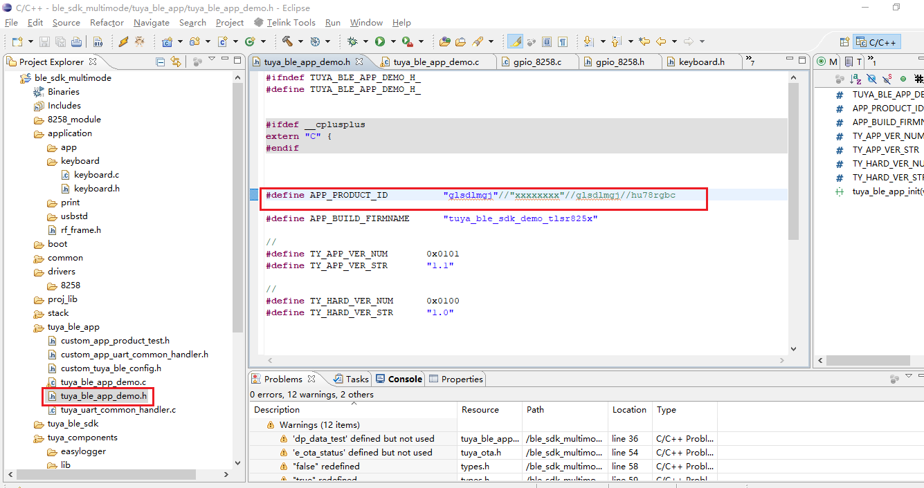
-
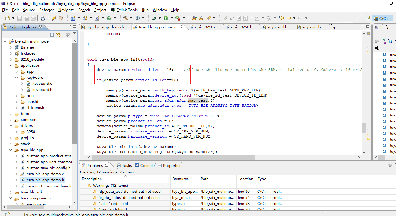
Edit the
auth_key,device_id, andmac.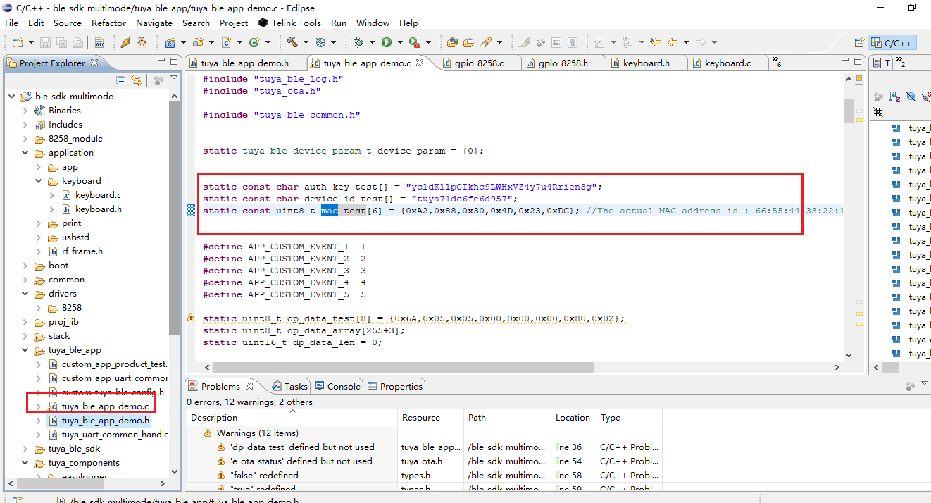
-
Compile code.
-
-
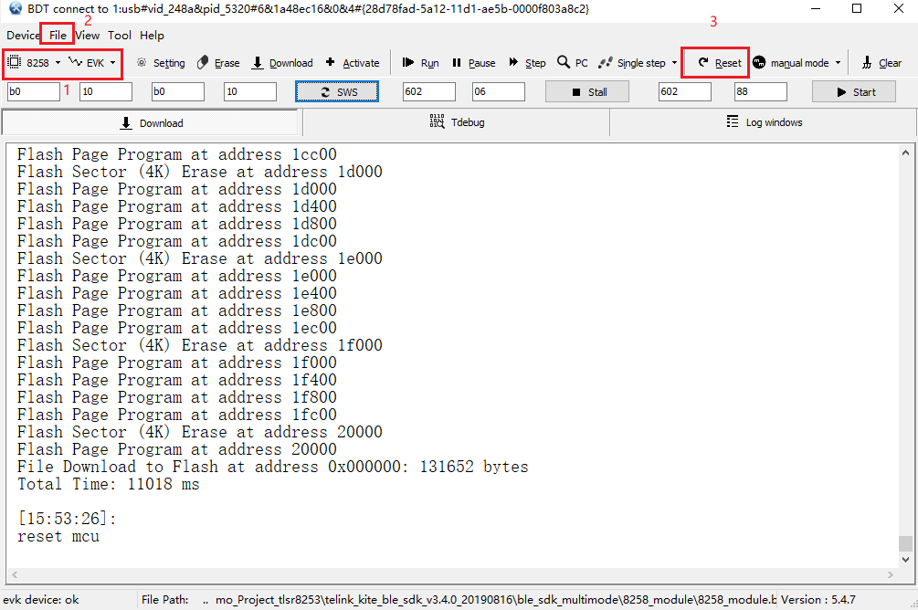
Flashing tool (Download)
-
Select
8258as the chip type andEVKas the download mode. Click File and select thebinfile to be downloaded into the board, which is located intuya_ble_sdk_Demo_Project_tlsr8253\telink_kite_ble_sdk_v3.4.0_20190816\ble_sdk_multimode\8258_module\8258_module.bin. -
After downloading, click Reset to run it.
-
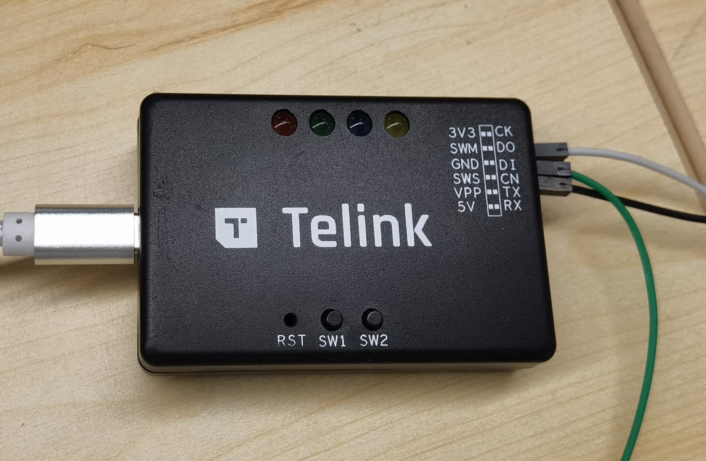
We use Telink’s writer. Connect the SWM header on the board to the SWM header on the writer.
Note:
- When the GPIO reads high, it returns a value greater than 1, which might be 1, 2, or 128.
- The pin of log printing defaults to
TL_C2, with a baud rate of 230400. Since we do not have enough I/Os, we change the pin of log printing toTL_D3. You can compile code after the editing. The configuration file is located intuya_ble_sdk_Demo_Project_tlsr8253\telink_kite_ble_sdk_v3.4.0_20190816\ble_sdk_multimode\vendor\8258_module\app_config.h.
In line 47:
Changed to:
-
Step 4: Software design
For the electric pulse massagers, the electric pulse simulation of traditional Chinese physical therapy can promote blood circulation and relax the local muscles with the electrode pads designed to achieve a double massage effect.
We implement five pulse modes: smart, relax, active, tapping, and scraping.
Pulse modes
-
Schematic diagram
P9 and P24 control the triode on/off to produce electric pulses and enable different pulse modes.
-
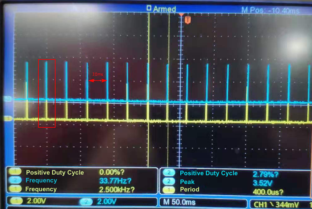
Oscillogram
P9 and P24 output PWM signals with a positive duty cycle of 26.5% and a period of 1 ms. Note that these two pins must not output high at the same time. Otherwise, the triode will be burned out.
Four PWM waves are output at a time with an interval of 30 ms to implement the relax mode.
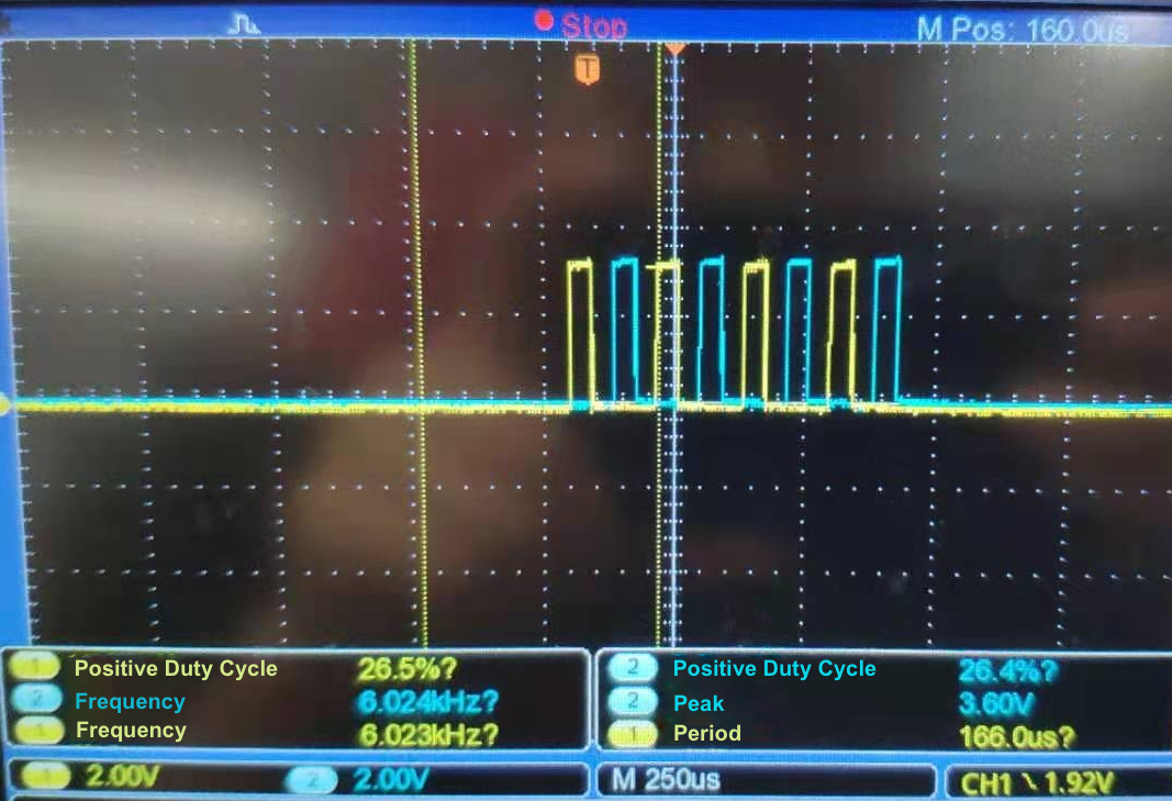
One pulse has four PWM waves, as shown above. Pulses are produced with an interval of 30 ms.
-
Mode implementation
The five pulse modes are implemented by changing pulse intervals, as shown in the following table.
Mode Time interval Relax mode 30 ms Active mode 20 ms Tapping mode 40 ms Scraping mode 50 ms Smart mode 20 ms, 30 ms, 40 ms, or 50 ms is generated randomly.
Implementation code
Pin initialization
void pattern_pin_init(void)
{
gpio_set_func(PATTERN_PIN_A, AS_PWM1_N);
gpio_set_func(PATTERN_PIN_B, AS_PWM5);
gpio_set_func(HEAT_PIN, AS_GPIO);
gpio_set_output_en(PATTERN_PIN_A, 1);
gpio_set_output_en(PATTERN_PIN_B, 1);
gpio_set_output_en(HEAT_PIN, 1);
gpio_write(PATTERN_PIN_A, 0);
gpio_write(PATTERN_PIN_B, 0);
// gpio_write(HEAT_PIN, 1);
//PWM0 1ms cycle 26.5% duty 1,000 Hz
pwm_set_mode(PWM1_ID, PWM_NORMAL_MODE);
pwm_set_clk(CLOCK_SYS_CLOCK_HZ, CLOCK_SYS_CLOCK_HZ);
pwm_set_phase(PWM1_ID, 0); // No phase at PWM beginning
pwm_set_cycle_and_duty(PWM1_ID, (u16) (1000 * CLOCK_SYS_CLOCK_1US), (u16) (0 * CLOCK_SYS_CLOCK_1US) );
pwm_polo_enable(PWM1_ID, 1); // Enable the PWM polarity
pwm_start(PWM1_ID);
// PWM5 1 ms cycle, 26.5% duty 1,000 Hz
pwm_set_mode(PWM5_ID, PWM_NORMAL_MODE);
pwm_set_clk(CLOCK_SYS_CLOCK_HZ, CLOCK_SYS_CLOCK_HZ);
pwm_set_phase(PWM5_ID, 0); // No phase at PWM beginning
pwm_set_cycle_and_duty(PWM5_ID, (u16) (1000 * CLOCK_SYS_CLOCK_1US), (u16) (265 * CLOCK_SYS_CLOCK_1US) );
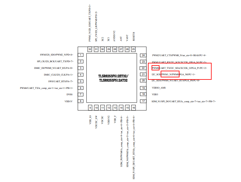
}
Both GPIO_PC1 (PATTERN_PIN_A) and level adjustment pin GPIO_PC2 (BOOST_PIN) use the PWM feature. The pin GPIO_PC1 (PATTERN_PIN_A) only supports the PWM_0 channel, so GPIO_PC2 (BOOST_PIN) uses the PWM_0 channel. GPIO_PC1 (PATTERN_PIN_A) uses the AS_PWM1_N channel so you only need to edit pwm_polo_enable(PWM1_ID, 1) to change the PWM polarity.
Since the number of PWM waves and pulse intervals are implemented by time delay, errors can be produced. The program runs on the bare metal, not the RTOS, so this function must run in a while(1) loop.
void switching_pattern(unsigned char pat)
{
	if (pat > 4) {
		TUYA_APP_LOG_ERROR("*********No such model!!!**********");
	}

	switch (pat) {
	case relieve:
		pwm_start(PWM5_ID);
			sleep_us(450);	 	// Delay 480 μs to prevent the triode from being burned out.
		pwm_set_cycle_and_duty(PWM1_ID, (u16) (1000 * CLOCK_SYS_CLOCK_1US),  (u16) (265 * CLOCK_SYS_CLOCK_1US) );
		sleep_us(5 * TIME_MS);
		pwm_stop(PWM5_ID);
		pwm_set_cycle_and_duty(PWM1_ID, (u16) (1000 * CLOCK_SYS_CLOCK_1US),  (u16) (0 * CLOCK_SYS_CLOCK_1US) );
		sleep_us(30 * TIME_MS);
		break;

	case vitality:
		pwm_start(PWM5_ID);
		sleep_us(450);
		pwm_set_cycle_and_duty(PWM1_ID, (u16) (1000 * CLOCK_SYS_CLOCK_1US),  (u16) (265 * CLOCK_SYS_CLOCK_1US) );
		sleep_us(5 * TIME_MS);
		pwm_stop(PWM5_ID);
		pwm_set_cycle_and_duty(PWM1_ID, (u16) (1000 * CLOCK_SYS_CLOCK_1US),  (u16) (0 * CLOCK_SYS_CLOCK_1US) );
		sleep_us(20 * TIME_MS);
		break;

	case hammering:
		pwm_start(PWM5_ID);
		sleep_us(450);
		pwm_set_cycle_and_duty(PWM1_ID, (u16) (1000 * CLOCK_SYS_CLOCK_1US),  (u16) (265 * CLOCK_SYS_CLOCK_1US) );
		sleep_us(5 * TIME_MS);
		pwm_stop(PWM5_ID);
		pwm_set_cycle_and_duty(PWM1_ID, (u16) (1000 * CLOCK_SYS_CLOCK_1US),  (u16) (0 * CLOCK_SYS_CLOCK_1US) );
		sleep_us(40 * TIME_MS);
		break;

	case scraping_therapy:
		pwm_start(PWM5_ID);
		sleep_us(450);
		pwm_set_cycle_and_duty(PWM1_ID, (u16) (1000 * CLOCK_SYS_CLOCK_1US),  (u16) (265 * CLOCK_SYS_CLOCK_1US) );
		sleep_us(5 * TIME_MS);
		pwm_stop(PWM5_ID);
		pwm_set_cycle_and_duty(PWM1_ID, (u16) (1000 * CLOCK_SYS_CLOCK_1US),  (u16) (0 * CLOCK_SYS_CLOCK_1US) );
		sleep_us(50 * TIME_MS);
		break;

	case intelligent:
		pwm_start(PWM5_ID);
		sleep_us(450);
		pwm_set_cycle_and_duty(PWM1_ID, (u16) (1000 * CLOCK_SYS_CLOCK_1US),  (u16) (265 * CLOCK_SYS_CLOCK_1US) );
		sleep_us(5 * TIME_MS);
		pwm_stop(PWM5_ID);
		pwm_set_cycle_and_duty(PWM1_ID, (u16) (1000 * CLOCK_SYS_CLOCK_1US),  (u16) (0 * CLOCK_SYS_CLOCK_1US) );
			sleep_us(((rand() % 4 + 2) * 10) * TIME_MS);	 // 20 ms, 30 ms, 40 ms, or 50 ms is generated randomly.
		break;
	default:
		break;
	}
	return;
}
We have implemented the five pulse modes, next we move to voice prompts, heating, and level adjustment.
1. Voice prompts
WTN6 is a multi-functional single voice chip, a speech synthesis 4-bit MCU.
- Working voltage: 2.8V to 5.2V
- In standby mode, the quiescent current is less than 5 μA.
- Precisely embedded oscillator with a build-in resistor (+/- 1%). Low voltage reset (LVR=1.8V) and watch-dog reset are all supported.
- High-quality 12-bit PWM directly drives 8Ω 0.5W speaker or buzzer. DAC converter audio output can amplify the volume by an external audio amplifier.
- Built-in watchdog.
- Serial port control mode: one-line serial port and two-line serial port. 224 pieces of voice can be loaded at most.
- Support output function in the busy state.
| Pin name | No. | Attribute | Description |
|---|---|---|---|
| PA2 | 1 | I/O | Outputs the busy signal. |
| PA1 | 2 | I/O | Two-line serial port clock signal input terminal, one-line serial port data signal input terminal, and pulse data signal input terminal. |
| PA0 | 3 | I/O | Two-line serial port data signal input terminal and reset pin. |
| PA3 | 4 | I/O | Not connected (NC). |
| PWM- | 5 | out | PWM output pin. |
| VDD | 6 | Power | Positive electrode. |
| PWM+/DAC | 7 | I/O | PWM and DAC output pin. |
| GND | 8 | Power | Negative electrode. |
One-line serial communication
In one-line serial port mode, the BTU module can control and send data to the voice chip through the DATA line to have voice play, stop, loop, and more.
-
Pin configuration
Pin Description PA1 DATA PA2 BUSY -
One-line audio address correlation
Data (hexadecimal) Function 00H No audio play. 01H The 1st audio play. 02H The 2nd audio play. …… …… DFH The 222nd audio play.
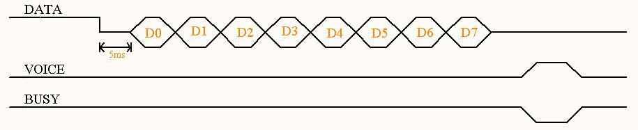
One-line serial port sequence diagram
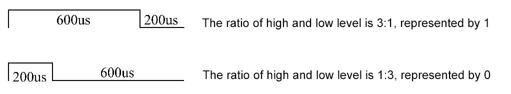
Pull data line low to 5 ms, and then send 8-bit data, low bit first, then high bit. Use the ratio of high level to low level to represent the value of each data bit.
Implementation code
-
Pin initialization
void voice_prompt_init(void) { gpio_set_func(WTN6_DATA_PIN | WTN6_BUSY_PIN, AS_GPIO); gpio_set_input_en(WTN6_BUSY_PIN, 1); gpio_set_output_en(WTN6_DATA_PIN, 1); gpio_write(WTN6_BUSY_PIN, 0); } -
Audio play
void voice_playing(uint8_t sb_data)
{
	uint8_t s_data, j;
	bool b_data;
	s_data = sb_data;
	gpio_write(WTN6_DATA_PIN, 0);
		sleep_us(5000);	 	// Delay 5 ms
	b_data = s_data & 0X01;

	for (j=0; j<8; j++) {
		if (b_data == 1) {
			gpio_write(WTN6_DATA_PIN, 1);
			   sleep_us(600); // Delay 600 μs
			gpio_write(WTN6_DATA_PIN, 0);
			   sleep_us(200); // Delay 200 μs
		} else {
			gpio_write(WTN6_DATA_PIN, 1);
			   sleep_us(200); // Delay 200 μs
			gpio_write(WTN6_DATA_PIN, 0);
			   sleep_us(600); // Delay 600 μs
		}
			s_data = s_data >> 1;
			b_data = s_data & 0X01;
	}
	gpio_write(WTN6_DATA_PIN, 1);
}
Specify parameters in voice_playing(0x01) to play offline audio.
2: Heating
We pull P7 up or down to control heating on/off. The neck massager has a built-in sensor to detect the temperature. When the temperature exceeds 40°C, heating will be turned off to avoid excessive heat.
int switching_heat(unsigned char warm)
{
	if (warm > 1) {
		TUYA_APP_LOG_ERROR("*********No such model!!!**********");
	}
//	printf("wram%d massage_state.heat%d\r\n", warm, massage_state.heat);

	switch (warm) {
	case strong_heat:
		TUYA_APP_LOG_INFO("**********strong_heat************");
		gpio_write(HEAT_PIN, 1);
		temperature_detection();
		break;
	case off_heat:
		TUYA_APP_LOG_INFO("**********off_heat************");
		gpio_write(HEAT_PIN, 0);
		break;

	default:
		break;
	}

	return 0;
}
/*Temperature detection, which is called when heating feature is in high or low level.*/
int temperature_detection(void)
{
	int Rntc = 0, Vcc = 0;
	adc_channel_checkout(channel_x1);
	Vcc = adc_sample_and_get_result();	 // Unit: mV
	Rntc = Vcc*R25 / (3300-Vcc);
	TUYA_APP_LOG_INFO("Rntc_val=%dΩ", Rntc);
	if (Rntc >= 5311) {  	// NTC resistance value is 5311Ω at 40°C.
		TUYA_APP_LOG_WARNING("********High Temperature Warning!!!********");
		 gpio_write(HEAT_PIN, 0);  // When the temperature exceeds 40°C, heating will be turned off.
	}

	return 0;
}
For more information about how the NTC temperature correlates with the resistance, see The relation between temperature and resistance.
3: Intensity adjustment
The massager provides 15-level intensity from weak to strong. We implement this feature with a boost circuit.
We can change the positive duty cycle of the PWM waves output from P8 to step up the voltage. The following table lists the specific values.
| Level | 1 | 2 | 3 | 4 | 5 | 6 | 7 | 8 | 9 | 10 | 11 | 12 | 13 | 14 | 15 | Max |
|---|---|---|---|---|---|---|---|---|---|---|---|---|---|---|---|---|
| Step-up voltage (V) | 12 | 15 | 19 | 22 | 26 | 29 | 33 | 36 | 40 | 43 | 47 | 50 | 54 | 57 | 60 | 60 |
| Duty cycle (%) | 1 | 2 | 4 | 6 | 7 | 9 | 12 | 16 | 18 | 22 | 24 | 26 | 30 | 34 | 36 | 36 |
The intensity is adjusted by a button press. Single-press can increase the level and double-press can decrease the level. Due to the SDK configuration, P8 has been pulled up on module reset after firmware flashing. Therefore, we need to pull down P8.
void boost_init(void)
{
	gpio_set_func(BOOST_PIN, AS_PWM0);
	gpio_set_output_en(BOOST_PIN, 1);
	// PWM0 1ms cycle
	pwm_set_mode(PWM0_ID, PWM_NORMAL_MODE);
	pwm_set_clk(CLOCK_SYS_CLOCK_HZ, BOOST_PWM_CLOCK_HZ); // When voltage is stepped up, the frequency of PWM is 16M / (968-1) ≈ 16.55 kHz.
	pwm_set_phase(PWM0_ID, 0);   // No phase at PWM beginning
	pwm_set_cycle_and_duty(PWM0_ID, (u16) (1000 * CLOCK_SYS_CLOCK_1US),  (u16) (0 * CLOCK_SYS_CLOCK_1US) );
	pwm_start(PWM0_ID);
}
After the initialization, you can specify the value of the duty cycle to step up the voltage.
void switching_gear(unsigned char gears)
{
	if (gears > 15) {
		TUYA_APP_LOG_ERROR("*********There is no such gear!!!**********");
	}

	switch (gears) {
	case first_gear:
		pwm_set_cycle_and_duty(PWM0_ID, (u16) (1000 * CLOCK_SYS_CLOCK_1US),  (u16) (10 * CLOCK_SYS_CLOCK_1US) );

		break;
	case second_gear:
		pwm_set_cycle_and_duty(PWM0_ID, (u16) (1000 * CLOCK_SYS_CLOCK_1US),  (u16) (20 * CLOCK_SYS_CLOCK_1US) );

		break;
	case third_gear:
		pwm_set_cycle_and_duty(PWM0_ID, (u16) (1000 * CLOCK_SYS_CLOCK_1US),  (u16) (40 * CLOCK_SYS_CLOCK_1US) );

		break;
	case fourth_gear:
		pwm_set_cycle_and_duty(PWM0_ID, (u16) (1000 * CLOCK_SYS_CLOCK_1US),  (u16) (60 * CLOCK_SYS_CLOCK_1US) );

		break;
	case fifth_gear:
		pwm_set_cycle_and_duty(PWM0_ID, (u16) (1000 * CLOCK_SYS_CLOCK_1US),  (u16) (70 * CLOCK_SYS_CLOCK_1US) );

		break;
	case sixth_gear:
		pwm_set_cycle_and_duty(PWM0_ID, (u16) (1000 * CLOCK_SYS_CLOCK_1US),  (u16) (90 * CLOCK_SYS_CLOCK_1US) );

		break;
	case seventh_gear:
		pwm_set_cycle_and_duty(PWM0_ID, (u16) (1000 * CLOCK_SYS_CLOCK_1US),  (u16) (120 * CLOCK_SYS_CLOCK_1US) );

		break;
	case eighth_gear:
		pwm_set_cycle_and_duty(PWM0_ID, (u16) (1000 * CLOCK_SYS_CLOCK_1US),  (u16) (160 * CLOCK_SYS_CLOCK_1US) );

		break;
	case ninth_gear:
		pwm_set_cycle_and_duty(PWM0_ID, (u16) (1000 * CLOCK_SYS_CLOCK_1US),  (u16) (180 * CLOCK_SYS_CLOCK_1US) );

		break;
	case tenth_gear:
		pwm_set_cycle_and_duty(PWM0_ID, (u16) (1000 * CLOCK_SYS_CLOCK_1US),  (u16) (220 * CLOCK_SYS_CLOCK_1US) );

		break;
	case eleventh_gear:
		pwm_set_cycle_and_duty(PWM0_ID, (u16) (1000 * CLOCK_SYS_CLOCK_1US),  (u16) (240 * CLOCK_SYS_CLOCK_1US) );

		break;
	case twelfth_gear:
		pwm_set_cycle_and_duty(PWM0_ID, (u16) (1000 * CLOCK_SYS_CLOCK_1US),  (u16) (260 * CLOCK_SYS_CLOCK_1US) );

		break;
	case thirteenth_gear:
		pwm_set_cycle_and_duty(PWM0_ID, (u16) (1000 * CLOCK_SYS_CLOCK_1US),  (u16) (300 * CLOCK_SYS_CLOCK_1US) );

		break;
	case fourteenth_gear:
		pwm_set_cycle_and_duty(PWM0_ID, (u16) (1000 * CLOCK_SYS_CLOCK_1US),  (u16) (340 * CLOCK_SYS_CLOCK_1US) );

		break;
	case fifteenth_gear:
		pwm_set_cycle_and_duty(PWM0_ID, (u16) (1000 * CLOCK_SYS_CLOCK_1US),  (u16) (360 * CLOCK_SYS_CLOCK_1US) );

		break;
	case max_gear:
		pwm_set_cycle_and_duty(PWM0_ID, (u16) (1000 * CLOCK_SYS_CLOCK_1US),  (u16) (360 * CLOCK_SYS_CLOCK_1US) );

		break;
	default:
		break;
	}
}
4: Power-off memory
Write the status data of the device before power-off to the available flash memory. Read data from the flash when the device is powered on again. This way, the device can resume its previous status after power-on.
The flash of the TLSR8253 chip is shown below.

0x040000 to 0x060000 is the unused space, to which the device can write data.
-
Write status to the flash memory.
/*********************************************************** * Function: write_massage_status_to_flash * Input: none * Output: none * Return: none * Notice: Write massager status to the flash memory. ***********************************************************/ void write_massage_status_to_flash(void) { Flash_Write_Buff[0] = massage_state.on_off; Flash_Write_Buff[1] = massage_state.pattern; Flash_Write_Buff[2] = massage_state.gear; Flash_Write_Buff[3] = massage_state.heat; flash_write_page(FLASH_ADDR, FLASH_BUFF_LEN, (unsigned char *)Flash_Write_Buff); return; } -
Read status from the flash memory.
/********************************************************************** * Function: read_massage_status_to_flash * Input: none * Output: none * Return: none * Notice: Read the massager status data before power-off from the flash memory, and save it to the status struct. **********************************************************************/ void read_massage_status_to_flash(void) { flash_read_page(FLASH_ADDR, FLASH_BUFF_LEN, (unsigned char *)Flash_Read_Buff); // Store the data read from the flash memory into the struct. massage_state.on_off = Flash_Read_Buff[0]; massage_state.pattern = Flash_Read_Buff[1]; massage_state.gear = Flash_Read_Buff[2]; massage_state.heat = Flash_Read_Buff[3]; return; } -
Restore defaults.
/***********************************************************
*   Function:  erase_massage_flash
*   Input:     none
*   Output:    none
*   Return:    none
*   Notice:    Restore defaults
***********************************************************/
void erase_massage_flash(void)
{
	massage_state.on_off = OFF;
	massage_state.pattern = relieve;
	massage_state.gear = first_gear;
	massage_state.heat = off_heat;

	Flash_Write_Buff[0] = OFF;
	Flash_Write_Buff[1] = relieve;
	Flash_Write_Buff[2] = first_gear;
	Flash_Write_Buff[3] = off_heat;

	flash_write_page(FLASH_ADDR, FLASH_BUFF_LEN, (unsigned char *)Flash_Write_Buff);

	return;
}
5: Control from the cloud
For the Bluetooth Low Energy module, all the data of a single data point (DP) is stored in one array. Take DP ID 104 as an example. Its array is as follows.
unsigned char mode_buf[]   = {0x68, 0x04, 0x01, 0x00};  //{DP_ID, DP_type, DP_len, DP_data}
tuya_ble_dp_data_report(mode_buf, 4);  // Data reporting function.
Call tuya_ble_dp_data_report(uint8_t *p_data,uint32_t len) to report the status data of a single DP to the cloud.
The control commands from the mobile app are stored in the array dp_data_array[255+3]. You can write a DP data sending processing function and pass dp_data_array[255+3] as an parameter to the function tuya_cb_handler(tuya_ble_cb_evt_param_t* event) in the tuya_ble_demo.c to implement command sending from the mobile app.
void app_dp_handle(uint8_t *dp_data)
{
	printf("dp_data:%d  %d  %d  %d\r\n", dp_data[0], dp_data[1], dp_data[2], dp_data[3]);
	switch (dp_data[0]) {
	case 0x66:
		if (dp_data[3] == strong_heat) {
			massage_state.heat = strong_heat;
		} else {
			massage_state.heat = off_heat;
		}
		printf("dp_data[3]:%d massage_state.heat:%d\r\n", dp_data[3], massage_state.heat);
		if (!app_flag) {
			switching_heat(massage_state.heat);
		}
		break;
	case 0x67:
		printf("dp_data[3]:%d \r\n", dp_data[3]);

		switch (dp_data[3]) {
		case first_gear:
			massage_state.gear = first_gear;
			if (!app_flag) {
				switching_gear(massage_state.gear);
			}
			break;
		case second_gear:
			massage_state.gear = second_gear;
			if (!app_flag) {
				switching_gear(massage_state.gear);
			}
			break;
		case third_gear:
			massage_state.gear = third_gear;
			if (!app_flag) {
				switching_gear(massage_state.gear);
			}
			break;
		case fourth_gear:
			massage_state.gear = fourth_gear;
			if (!app_flag) {
				switching_gear(massage_state.gear);
			}
			break;
		case fifth_gear:
			massage_state.gear = fifth_gear;
			if (!app_flag) {
				switching_gear(massage_state.gear);
			}
			break;
		case sixth_gear:
			massage_state.gear = sixth_gear;
			if (!app_flag) {
				switching_gear(massage_state.gear);
			}
			break;
		case seventh_gear:
			massage_state.gear = seventh_gear;
			if (!app_flag) {
				switching_gear(massage_state.gear);
			}
			break;
		case eighth_gear:
			massage_state.gear = eighth_gear;
			if (!app_flag) {
				switching_gear(massage_state.gear);
			}
			break;
		case ninth_gear:
			massage_state.gear = ninth_gear;
			if (!app_flag) {
				switching_gear(massage_state.gear);
			}
			break;
		case tenth_gear:
			massage_state.gear = tenth_gear;
			if (!app_flag) {
				switching_gear(massage_state.gear);
			}
			break;
		case eleventh_gear:
			massage_state.gear = eleventh_gear;
			if (!app_flag) {
				switching_gear(massage_state.gear);
			}
			break;
		case twelfth_gear:
			massage_state.gear = twelfth_gear;
			if (!app_flag) {
				switching_gear(massage_state.gear);
			}
			break;
		case thirteenth_gear:
			massage_state.gear = thirteenth_gear;
			if (!app_flag) {
				switching_gear(massage_state.gear);
			}
			break;
		case fourteenth_gear:
			massage_state.gear = fourteenth_gear;
			if (!app_flag) {
				switching_gear(massage_state.gear);
			}
			break;
		case fifteenth_gear:
			massage_state.gear = fifteenth_gear;
			if (!app_flag) {
				switching_gear(massage_state.gear);
			}
			break;
		case max_gear:
			massage_state.gear = max_gear;
			if (!app_flag) {
				switching_gear(massage_state.gear);
			}
			break;
		default:
			break;
		}
		break;
	case 0x68:
		if (dp_data[3] == relieve) {
			massage_state.pattern = relieve;

		} else if (dp_data[3] == vitality) {
			massage_state.pattern = vitality;
		} else if (dp_data[3] == hammering) {
			massage_state.pattern = hammering;
		} else if (dp_data[3] == scraping_therapy) {
			massage_state.pattern = scraping_therapy;
		} else {
			massage_state.pattern = intelligent;
		}

		break;
	case 0x69:
		if (dp_data[3] == ON) {
			massage_state.on_off = ON;
			rs2255_init();
			voice_prompt_init();
			pattern_pin_init();
			app_flag = 0;
		} else {
			massage_state.on_off = OFF;
			power_off_init();
			app_flag = 1;
		}
		break;

	default:
		break;
	}
}
Step 5: Device control
Install the Tuya Smart app or Smart Life app on your mobile phone. They are available in mobile app markets. Open the app and click the + icon in the top right corner to pair the device. After the device is connected, you can control it with the app.
Summary
Congratulations! You have successfully prototyped a smart neck massager.
This multi-functional IoT-enabled massager is coupled with the TENS technology to help relieve neck soreness and pain. The built-in NTC sensor with advanced precise constant-temperature control technique can improve blood circulation and relieve pains, knots, and muscle tension. Based on this project, you can explore more awesome features!
Tuya IoT Platform provides convenient IoT development tools and services, which are designed to make your IoT projects much easier and more efficient. Check it out and discover more awesome ideas.
Is this page helpful?
YesSuggestions


