Prototype a Wi-Fi Smart Fan with Tuya MCU Connection Solution

Overview
A smart fan is a common smart device which the user can easily control with an app. A warm, relaxing, and comfortable room can be created by remote control of the switch, fan speed, and scene linkage. This demo describes how to quickly create a prototype of a safe smart fan with Keil5 coding based on Tuya IoT platform and Sandwich BLDC function board.
Solution overview
Being different from the SoC solution, the driver code of sensors and network modules in the MCU solution is written in the MCU. You can develop the MCU code with more traits.
In the Tuya Sandwich Development Board BLDC kit, the BLDC board receives the PWM from NUCLEO-G071RB through the PWM API, and then drives the motor through the duty cycle of the received PWM. The MCU control board connects to the Wi-Fi communication board through the serial port. After pairing through the Tuya Smart app, the output parameter status of the BLDC is displayed on the phone. The MCU model is STM32G071RB.
Related information
Implement an efficient FOC motor drive with just simple peripheral processing. The sensitive start and non-inductive operation FOC drive of the FU6832 mainly applies to various low-pressure fans such as floor fans, air purifiers, and more.
Note: Though the BLDC function board supports serial port, button, and PWM control, the MCU control board and Wi-Fi communication board communicate through the serial port in the lower right corner. In order to reduce the impact on BLDC control, the function board only supports PWM control by default.
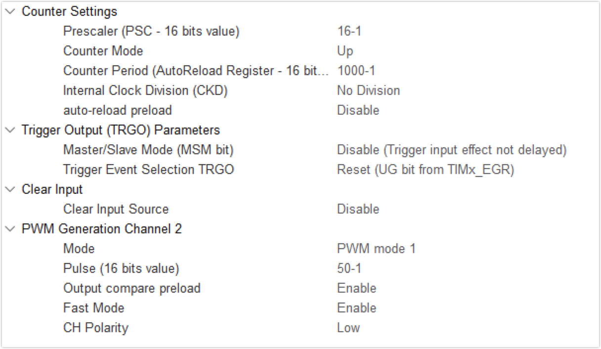
The sampling frequency of the BLDC board is 12M. The motor speed is controlled by the PWM duty cycle. The greater the input PWM duty cycle, the higher the motor speed. The preset output frequency in this demo is 1000 Hz.
- Start-up PWM duty cycle: 0.08. It starts when the duty cycle is over 0.08.
- Shutdown PWM duty cycle: 0.06. It shuts down when the duty cycle is below 0.06. (Shutdown duty cycle is not supposed to be in the value range of the rotation reversal duty cycle)
- Rotation reversal PWM duty cycle: 0.01–0.025. It ceases and reverses the rotation when the duty cycle falls into this range.
- The PWM output polarity is low.
The example of PWM configuration (The basic frequency is 16M) is as follows:
Materials
Tuya Sandwich Wi-Fi MCU communication board (WB3S)
Count:1The onboard Tuya WB3S module is responsible for the smart connection. The module has been programmed with general firmware, and the MCU is connected to the Tuya serial port protocol to enable smart one-stop services of the Tuya module, app, and cloud.more
Tuya Sandwich function board of BLDC motor drive
Count:1Control the motor through the received PWM duty cycle.
Tuya Sandwich DC power supply board
Count:1Adopt the standard physical size of Arduino, so you can directly stack the corresponding development boards on top for power supply. 12V, 5V, and 3.3V power supply are required for the BLDC function board. The power board can reduce cable usage.more
NUCLEO-G071RB
Count:1Use ST official MCU master control board for sensor data receiving and module communication control. The NUCLEO-G071RB development board supports the Arduino interface.
Steps
Step 1: Hardware connection and routine environment
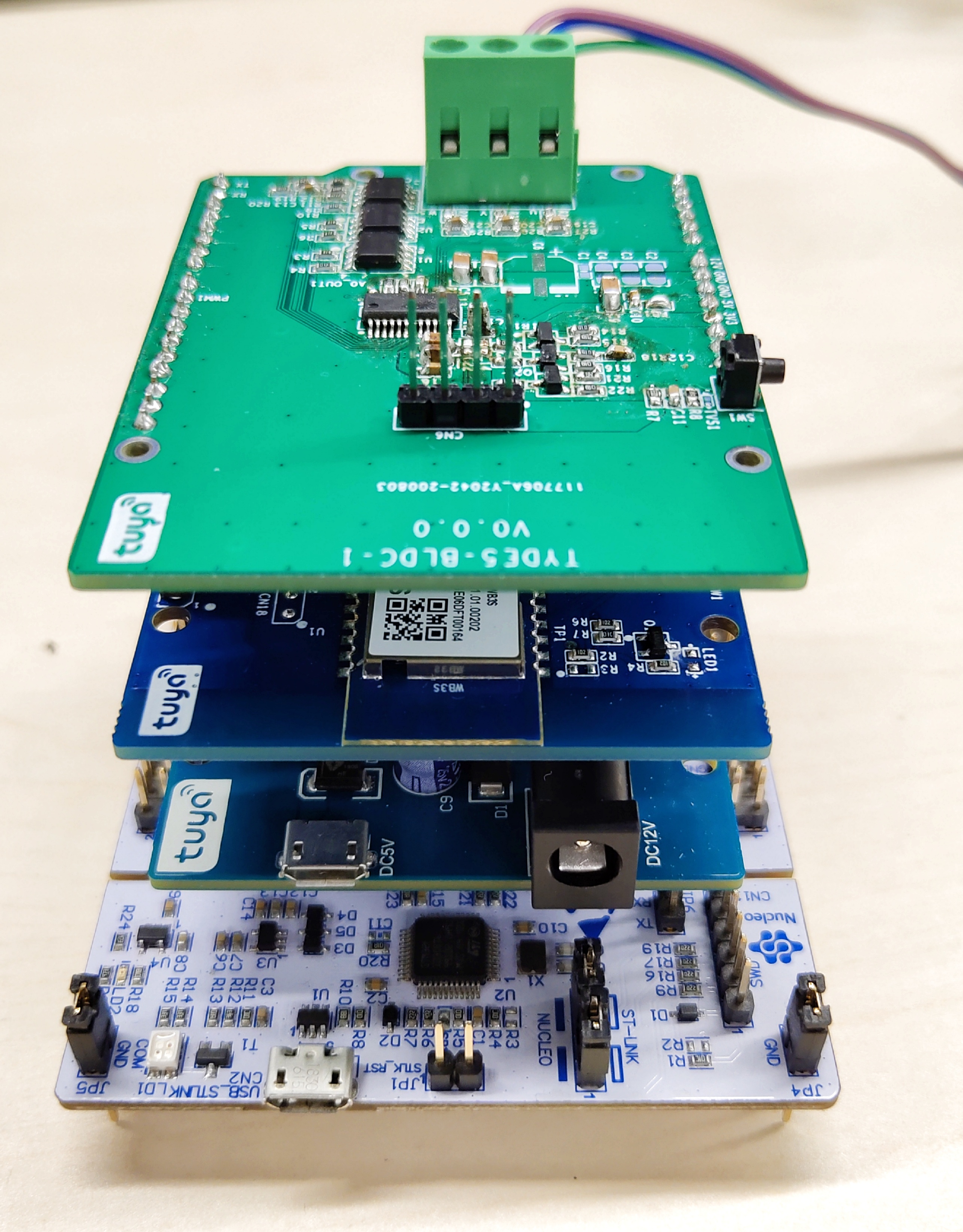
The BLDC kit of the Tuya Sandwich development board consists of the following:
- BLDC function board
- Wi-Fi MCU communication board
- NUCLEO-G071RB
- Tuya DC-DC power board
Assemble the power board, control board, communication board, and function board of the sandwich development board kit, as it is shown below.
The software development is mainly based on the connection of the MCU to the sensor and module protocol by Keil5. Make sure the communication between MCU and the module works properly to pair through the app and transfer MCU data to the app.
Step 2: Create product and project
You can quickly create a smart fan on the Tuya IoT platform by the following steps.-
Log in to the Tuya IoT Platform.
-
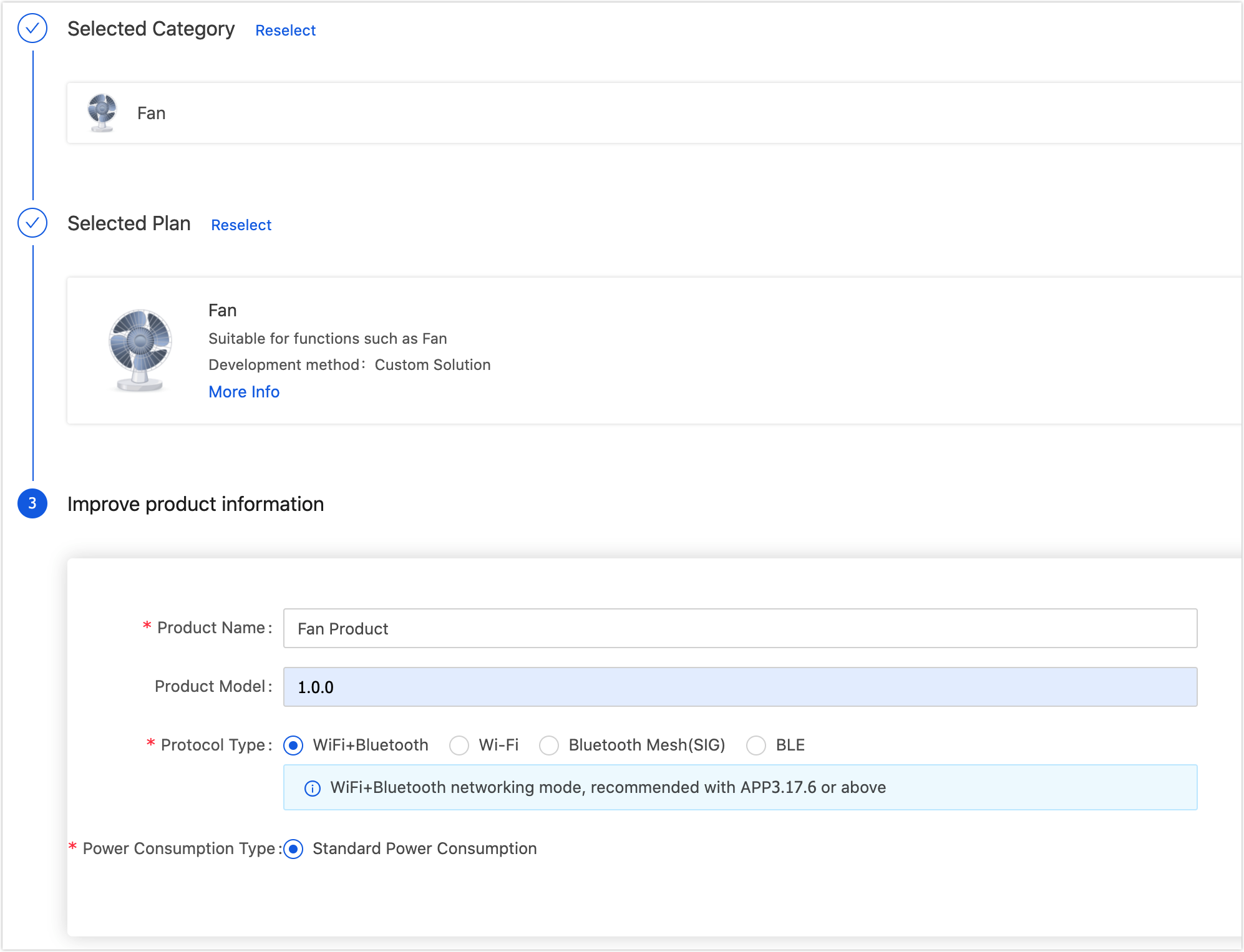
See Create Products to create a fan. The product attributes are as follows:
- Development method: Custom solution
- Net pairing mode: Wi-Fi
- Power type: Standard power consumption
-
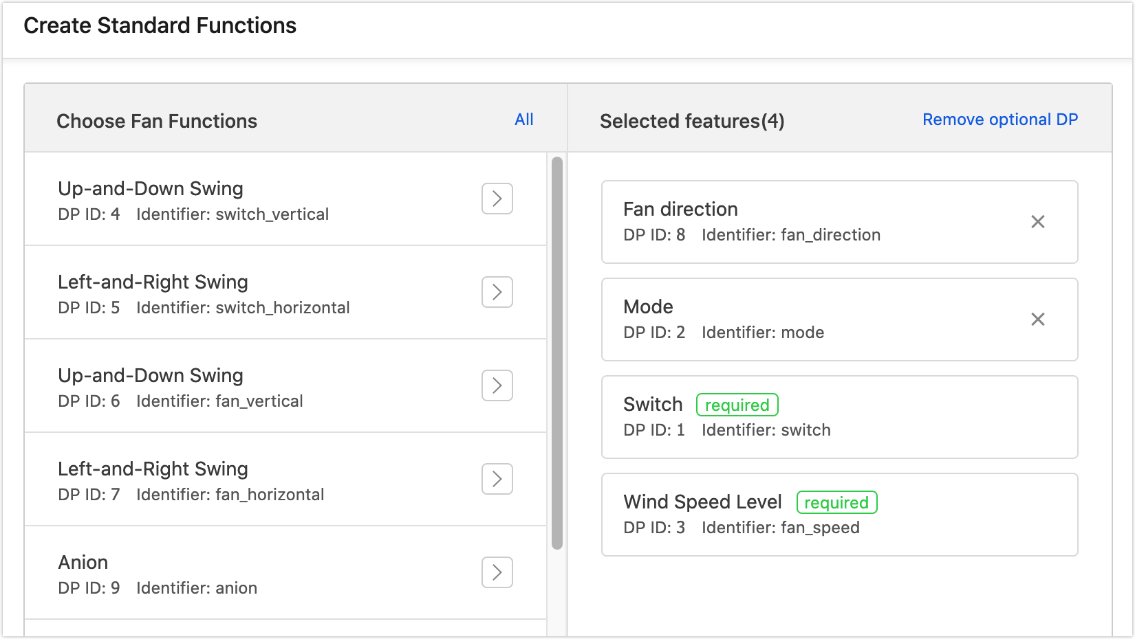
Select standard and custom functions for the product as per the prompts. For example, select the data point (DP) such as fan direction, fan speed, working mode, switch, and more.
You can also edit a certain DP. For example, if you select the working mode, you can proceed to change the mode to the natural wind and sleep wind.
-
Select an ideal panel. For the first time debugging, you can also select a development debugging panel, which can be changed in the following steps.
-
After selecting the panel, enter the Hardware Development stage and download development documents at the bottom of the page.
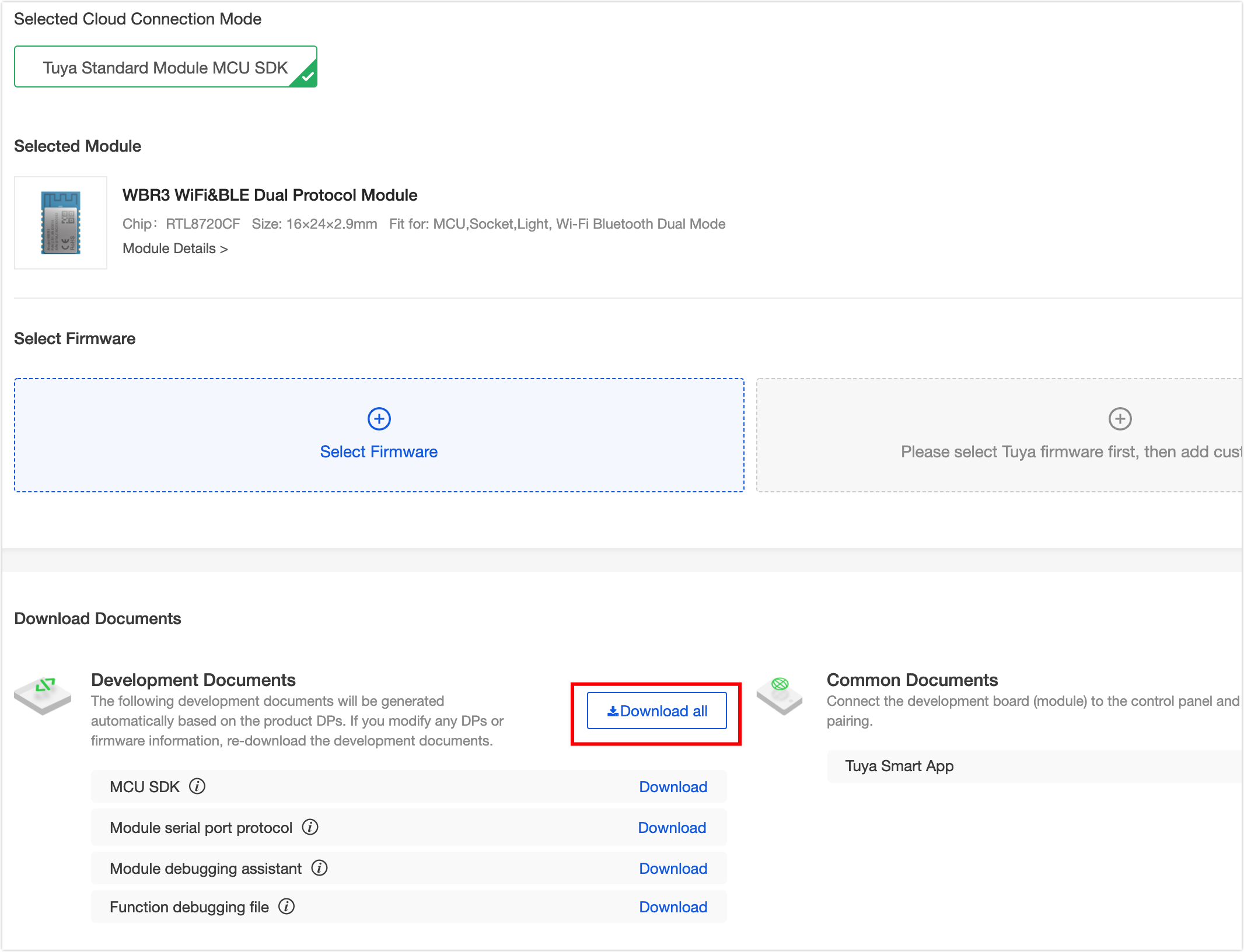
-
Hardware debugging.
After downloading MCU development documents, you can use the MCU simulation mode in the Tuya Module Debugging Assistant to debug the module communication board, verify whether the communication works properly, and get to know the Tuya serial port protocols for higher connection efficiency. If the communication board works properly, you can skip this step. If you have questions about protocol sending and receiving during debugging, you can also use this assistant to check the correct data transmission format. See Module Debugging Assistant for usage steps.
-
Step 3: Migrate MCU SDK
This section briefly describes the migrating procedure and function implementation. Import the documents in
mcu_sdkinto the project, then compile and modify as the error prompts. For more information about the migration debugging demo, see MCU SDK Migration.-
If any error like
#40: expected an identifier DISABLE = 0occurs during compiling, you can solve it with#include "stm32f1xx.h. The corresponding header file is the actual chip model. For example, a G071RB chip can be added as#include "stm32g0xx.h.
The macro ofWIFI_TEST_ENABLEis commented out since the Wi-Fi function test is not included in this demo.// #define WIFI_TEST_ENABLE -
Complete the
uart_transmit_output()function.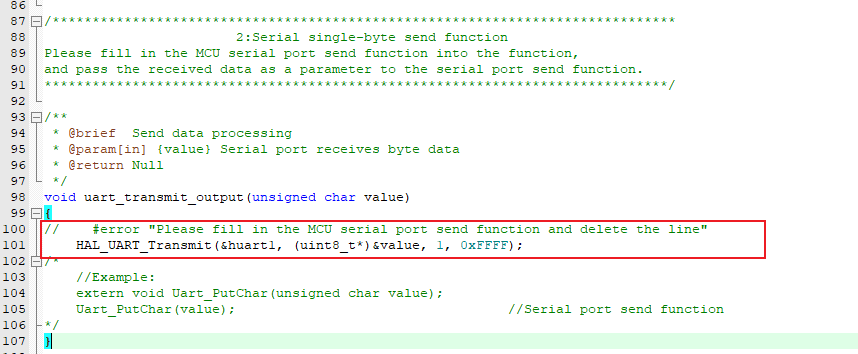
-
Complete the
uart_receive_input()function.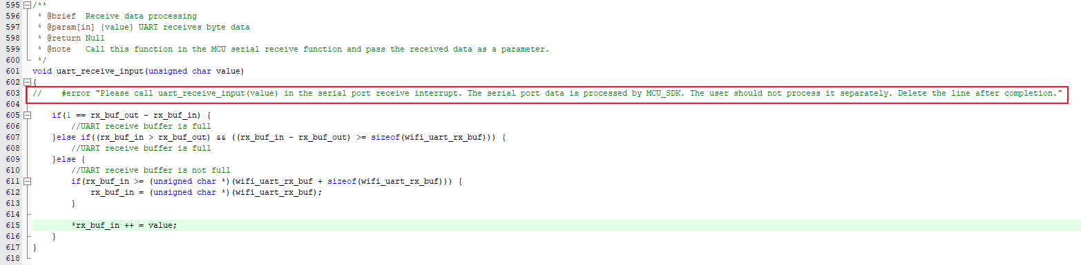
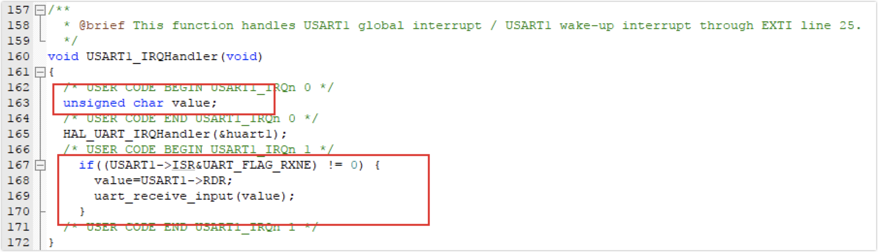
-
Add the following code to the interrupt service function of the serial port for connecting MCU and Wi-Fi communication board. Remember to add a header file or declare the function you call.
-
Process the
wifi_uart_service()function as per the prompts in the#error, and comment it out afterward.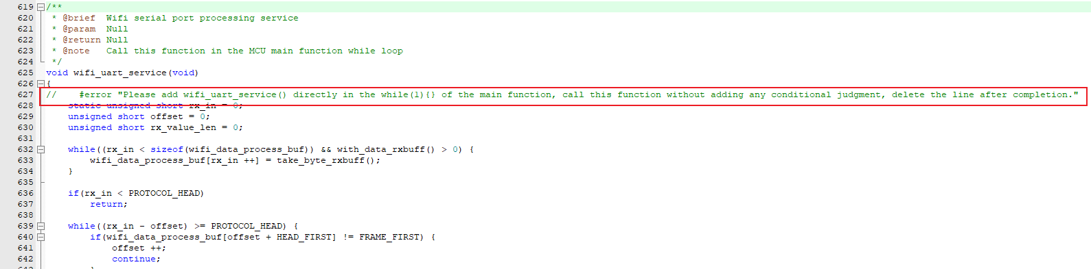
-
Process the
wifi_protocol_init()function as per the prompts in the#error, and comment it out afterward.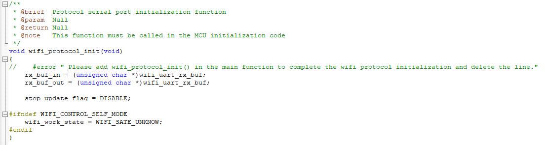
Do not call the
all_data_update()function as it reports all the DP information in the system automatically.-
Step 4: Define struct
Define a struct to record the working status of the fan.
// Working mode
typedef enum
{
nature = 0,
sleep
}
fan_mode_t;

// Clockwise and counter-clockwise rotation
typedef enum
{
forward = 0,
reverse
}
fan_direction_t;

// Fan working status struct
typedef struct
{
_Bool OnOff;
fan_mode_t e_fan_mode;
unsigned long speed;
fan_direction_t e_fan_direction;
}
fan_status_t;

// Fan status struct. Global variables.
fan_status_t gs_fan_status =
{
OnOff = FALSE,

e_fan_mode = nature,

speed = 10,

e_fan_direction = forward
};
Complete the four functions of
dp_download_switch_handle(),dp_download_mode_handle(),dp_download_fan_speed_handle(), anddp_download_fan_direction_handle()in theprotocol.cfile.
In thep_download_switch_handle()function in theprotocol.cfile.static unsigned char dp_download_switch_handle(const unsigned char value[], unsigned short length) { // Example: The current DP type is Bool unsigned char ret; //0: off /1: on unsigned char switch_1; switch_1 = mcu_get_dp_download_bool(value,length); if(switch_1 == 0) { // Switch off gs_fan_status.OnOff = FALSE; } else { // Switch on gs_fan_status.OnOff = TRUE; } //Feedback after processing DP data ret = mcu_dp_bool_update(DPID_SWITCH,switch_1); if(ret == SUCCESS) return SUCCESS; else return ERROR; }In the
dp_download_mode_handle()function in theprotocol.cfile:static unsigned char dp_download_mode_handle(const unsigned char value[], unsigned short length) { // Example: The current DP type is ENUM unsigned char ret; unsigned char mode; mode = mcu_get_dp_download_enum(value,length); switch(mode) { case 0: gs_fan_status.e_fan_mode = nature; // Natural wind mode break; case 1: gs_fan_status.e_fan_mode = sleep; // Sleep wind mode break; default: gs_fan_status.e_fan_mode = nature; break; } // Feedback after processing DP data ret = mcu_dp_enum_update(DPID_MODE, mode); if(ret == SUCCESS) return SUCCESS; else return ERROR; }In the
dp_download_fan_speed_handle()function in theprotocol.cfile:static unsigned char dp_download_fan_speed_handle(const unsigned char value[], unsigned short length) { // Example: The current DP type is VALUE unsigned char ret; unsigned long fan_speed; fan_speed = mcu_get_dp_download_value(value,length); /* // VALUE data processing */ gs_fan_status.speed = fan_speed; // Assign the speed value to the global variable // Feedback after processing DP data ret = mcu_dp_value_update(DPID_FAN_SPEED,fan_speed); if(ret == SUCCESS) return SUCCESS; else return ERROR; }In the
dp_download_fan_direction_handle()function in theprotocol.cfile:static unsigned char dp_download_fan_direction_handle(const unsigned char value[], unsigned short length) { // Example: The current DP type is ENUM unsigned char ret; unsigned char fan_direction; fan_direction = mcu_get_dp_download_enum(value,length); switch(fan_direction) { case 0: // Check whether the current rotation is reversed. If the current rotation is reversed, invert the rotation and assign the current status to the global variable. if(gs_fan_status.e_fan_direction != forward) { change_fan_direction(); gs_fan_status.e_fan_direction = forward; } break; case 1: // Check whether the current rotation is reversed. If the current rotation is not reversed, invert the rotation and assign the current status to the global variable. if(gs_fan_status.e_fan_direction != reverse) { change_fan_direction(); gs_fan_status.e_fan_direction = reverse; } break; default: break; } // Feedback after processing DP data ret = mcu_dp_enum_update(DPID_FAN_DIRECTION, fan_direction); if(ret == SUCCESS) return SUCCESS; else return ERROR; }Step 5: Implement function
Add header files #include “mcu_api.h” and #include “wifi.h” to the
main.cfile, and define the following macros and variables:// The output PWM duty cycle at the minimum speed. // The output PWM duty cycle at the maximum speed. // The output PWM duty cycle at the maximum speed should be 100 (it is recommended to set it as 99 at the maximum). A low value is set for demonstration. // The output PWM duty cycle during the shutdown. The output PWM duty cycle when the rotation is changed. The PWM output from the BLDC development board inverts the motor rotation within 1%–2.5%. The time when fan speed changes in the sleep mode. // The fan speed last time. Global variables. unsigned long last_fan_speed = 0; // Change the count value and flag of the fan speed in the sleep mode. Global variable. unsigned long fen_count = SLEEP_TIME; _Bool sleep_speed_flag = TRUE;After start-up, the following shall be processed before entering
while(1){}loop:void setup(void) // The prioritized output frequency is 1000 Hz and the duty cycle is 5%, so that the motor is in shutdown status. { HAL_TIM_PWM_Start(&htim3,TIM_CHANNEL_2); __HAL_TIM_SET_COMPARE(&htim3, TIM_CHANNEL_2, (OFF_SPEED * 10)); // Enable the UART1 that communicates with Tuya Sandwich Wi-Fi MCU communication board (E3S) to receive break. __HAL_UART_ENABLE_IT(&huart1, UART_IT_RXNE); // Completes the initialization of Wi-Fi protocol wifi_protocol_init(); }In the
while(1){}loop:while (1) { // Processing service of Wi-Fi serial port data wifi_uart_service(); // Enter the network pairing mode and prompt by changing the LED indicator status. connect_tuya(); if (gs_fan_status.OnOff == TRUE) { // Power on // Check the working mode check_mode(); } else { set_fan_speed(0); } } In the
connect_tuya()function:// This function is used to enter the network pairing mode when the PC3 is pulled down. Change the LED indicator status to prompt different network statuses. void connect_tuya(void) { // Determine whether the PC3 is pulled down. if (HAL_GPIO_ReadPin(WIFI_KEY_GPIO_Port, WIFI_KEY_Pin) == GPIO_PIN_RESET) { HAL_Delay(300); if (HAL_GPIO_ReadPin(WIFI_KEY_GPIO_Port, WIFI_KEY_Pin) == GPIO_PIN_RESET) { mcu_set_wifi_mode(0); } } // Get the current connection status and indicate LED prompts. switch(mcu_get_wifi_work_state()) { case SMART_CONFIG_STATE: // SmartConfig pairing mode. Flicker fast. HAL_GPIO_TogglePin(LED_GREEN_GPIO_Port, LED_GREEN_Pin); HAL_Delay(250); break; case AP_STATE: // AP pairing mode. Flicker fast. HAL_GPIO_TogglePin(LED_GREEN_GPIO_Port, LED_GREEN_Pin); HAL_Delay(250); break; case WIFI_NOT_CONNECTED: // Flicker slowly HAL_GPIO_TogglePin(LED_GREEN_GPIO_Port, LED_GREEN_Pin); HAL_Delay(250); break; case WIFI_CONNECTED: // Always on. Connected to Wi-Fi case WIFI_CONN_CLOUD: // Always on. Connected to Wi-Fi and the cloud platform. HAL_GPIO_WritePin(LED_GREEN_GPIO_Port, LED_GREEN_Pin, GPIO_PIN_SET); break; default: HAL_GPIO_WritePin(LED_GREEN_GPIO_Port, LED_GREEN_Pin, GPIO_PIN_RESET); break; } }In the
set_fan_speed()function:// This function is used to output the PWM according to different rotating speeds. The PWM frequency is 1,000 Hz. void set_fan_speed(unsigned long speed) { // When the input is 0, the motor shuts down. if (speed == 0) { __HAL_TIM_SET_COMPARE(&htim3, TIM_CHANNEL_2, (OFF_SPEED * 10)); last_fan_speed = OFF_SPEED; // Record the current rotating speed. return; } // Determine whether the input value falls out of the value range. if (speed < MIN_SPEED) { __HAL_TIM_SET_COMPARE(&htim3, TIM_CHANNEL_2, (MIN_SPEED * 10)); last_fan_speed = MIN_SPEED; } else if (speed > MAX_SPEED) { __HAL_TIM_SET_COMPARE(&htim3, TIM_CHANNEL_2, (MAX_SPEED * 10)); last_fan_speed = MAX_SPEED; } else { __HAL_TIM_SET_COMPARE(&htim3, TIM_CHANNEL_2, (speed * 10)); last_fan_speed = speed; } return; }In the
check_mode()function:void check_mode(void) { if (gs_fan_status.e_fan_mode == sleep) { // Enter the sleep mode if ((sleep_speed_flag == TRUE) && (fen_count >= SLEEP_TIME)) { set_fan_speed(gs_fan_status.speed); // Clear the count and change the fan speed fen_count = 0; sleep_speed_flag = FALSE; } else if ((sleep_speed_flag == FALSE) && (fen_count >= SLEEP_TIME)) { set_fan_speed(MIN_SPEED); // Clear the count and change the fan speed fen_count = 0; sleep_speed_flag = TRUE; } fen_count++; HAL_Delay(10); } else { if (last_fan_speed != gs_fan_status.speed) { // Change the speed if the rotating speed is different from the last one. set_fan_speed(gs_fan_status.speed); } } }On the Tuya IoT Platform, you can quickly make a prototype of a smart fan with a Sandwich development board in the Keil development environment.
Summary
More information
FU6832s is used as the master control chip of the BLDC function board. The FU6832 series is a high-performance dedicated motor drive chip integrated with a motor control engine (ME) and 8051 core. The ME integrates with FOC, MDU, LPF, PI, SVPWM/SPWM, and more hardware modules, to implement motor FOC/BLDC computing control automatically. The 8051 core is used for parameter configuration and routine handling, and the dual-core working achieves various high-performance motor control. The most instruction cycles in the 8051 core are 1T or 2T, and the chip integrates with a high-speed operation amplifier, comparator, Pre-driver, high-speed ADC, high-speed multiplier/divider, CRC, SPI, I2C, UART, LIN, various TIMER, PWM, and more functions, with the built-in high-pressure LDO. It is applicable to the square wave of the BLDC/PMSM motor, SVPWM/SPWM, and FOC drive control.
FU6832 is backed up by comprehensive protection including over-voltage protection, under-voltage protection, over-current protection, FO protection, locked protection, phase loss protection, over-temperature protection, over-power protection, and Op-amp bias abnormal voltage protection. Enable corresponding value as needed and slightly adjust accordingly.
Is this page helpful?
YesSuggestions


