T3AI-V 模组规格书
T3AI-V 是由杭州涂鸦信息技术有限公司开发的一款语音模组。它由一个高集成度无线射频和语音的 SOC 芯片 T3AI 构成,支持 Wi-Fi 和蓝牙低功耗(Bluetooth Low Energy,Bluetooth LE)双模无线协议。
产品概述
T3AI-V 是支持语音控制的 Wi-Fi AI 模组,集成涂鸦 AI 平台,可以通过语音交互,并通过涂鸦 AI Agent 连接各大 AI 平台,支持豆包、DeepSeek、通义千问、OpenAI、Gemini 等大模型。支持按键唤醒、唤醒词唤醒、随意对话等功能,可以为用户提供生动有趣的 AI 语音交互体验,适用于语音交互场景的智能产品。
特性
- 内置低功耗 32 位 CPU,可以兼作应用处理器
- 主频支持 480 MHz
- 工作电压:2.5 V - 3.6 V
- 外设:6×PWM、1×I2S、1×SDIO、2×QSPI、5×ADC 、2×UART 和 2×SPI
- Wi-Fi 连通性
- 802.11 b/g/n/ax
- 通道 1-14@2.4GHz
- 支持 WPA2、WPA2 PSK (AES) 和 WPA3 安全模式
- 802.11 b 模式下最大 +17 dBm 的平均输出功率
- 支持 STA/AP/STA+AP/Direct 工作模式
- 支持 蓝牙 和 AP 两种配网方式(包括 Android 和 iOS 设备)
- 板载 PCB 天线,天线峰值增益 2.56 dBi
- 工作温度:-40℃ 到 85℃
- 蓝牙连通性
- 低功耗蓝牙 V5.4 完整标准
- 蓝牙模式支持 6 dBm 发射功率
- 完整的蓝牙共存接口
- 板载 PCB 天线,天线峰值增益 2.56 dBi
应用领域
- AI 数娱产品
- 智慧家居/家电
- 智能插座、智慧灯
模组接口
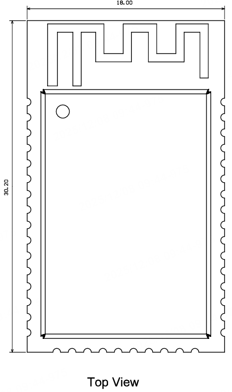
尺寸封装
T3AI-V 尺寸大小:18±0.35 mm (W) × 30.2±0.35 mm (L) × 3.0±0.15 mm (H)。T3AI-V 尺寸如下图所示:
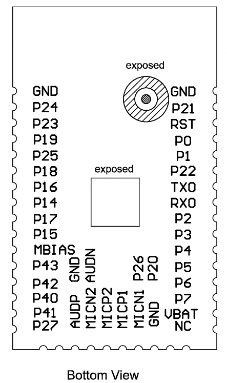
引脚定义
| 引脚序号 | 符号 | IO 类型 | 功能 |
|---|---|---|---|
| 1 | GND | P | 模组电源地 |
| 2 | P21 | I/O |
|
| 3 | RST | I | 模组复位引脚 |
| 4 | P0 | I/O | 日志串口,对应 T3AI 的 Log TX |
| 5 | P1 | I/O | 日志串口,对应 T3AI 的 Log RX |
| 6 | P22 | I/O |
|
| 7 | TX0 | I/O | 烧录口,对应芯片 T3AI 的 P11 |
| 8 | RX0 | I/O | 烧录口,对应芯片 T3AI 的 P10 |
| 9 | P2 | I/O |
|
| 10 | P3 | I/O |
|
| 11 | P4 | I/O |
|
| 12 | P5 | I/O |
|
| 13 | P6 | I/O |
|
| 14 | P7 | I/O |
|
| 15 | VBAT | P | 模组电源引脚 |
| 16 | NC | - | NC |
| 17 | P20 | I/O |
|
| 18 | P26 | I/O |
|
| 19 | GND | P | 模组模拟地 |
| 20 | MICN1 | AI | 麦克风 1 输入 Negative input |
| 21 | MICP1 | AI | 麦克风 1 输入 Positive input |
| 22 | MICP2 | AI | 麦克风 2 输入 Positive input |
| 23 | MICN2 | AI | 麦克风 2 输入 Negative input |
| 24 | AUDP | AO | 音频输出 Positive output |
| 25 | AUDN | AO | 音频输出 Negative output |
| 26 | GND | P | 模组地 |
| 27 | P27 | I/O |
|
| 28 | P41 | I/O |
|
| 29 | P40 | I/O |
|
| 30 | P42 | I/O |
|
| 31 | P43 | I/O |
|
| 32 | MBIAS | AO | 麦克风偏置电压 |
| 33 | P15 | I/O |
|
| 34 | P17 | I/O |
|
| 35 | P14 | I/O |
|
| 36 | P16 | I/O |
|
| 37 | P18 | I/O |
|
| 38 | P25 | I/O |
|
| 39 | P19 | I/O |
|
| 40 | P23 | I/O |
|
| 41 | P24 | I/O |
|
| 42 | GND | P | 模组地 |
- 由于上电毛刺(power-up glitches)的存在:P0,P4,P5,P10,P11,P20,P21,P22,P23 引脚不建议用在灯驱动或者电机驱动等对上电过程电平波动敏感的应用中。
- ADC 口输入电平最大值为 3.25 V,建议靠近 ADC 口放置对地 100 nF 电容滤波。
P表示电源引脚,I/O表示输入输出引脚。- 关于 MCU 对接方案,参考涂鸦设计文档 T3-X 系列模组 MCU 对接设计指南。
电气参数
绝对电气参数
| 参数 | 描述 | 最小值 | 最大值 | 单位 |
|---|---|---|---|---|
| Ts | 存储温度 | -55 | 125 | ℃ |
| VBAT | 供电电压 | -0.3 | 3.9 | V |
| 静电释放电压(人体模型) | TAMB-25℃ | -4 | 4 | kV |
| 静电释放电压(机器模型) | TAMB-25℃ | -200 | 200 | V |
正常工作条件
| 参数 | 描述 | 最小值 | 典型值 | 最大值 | 单位 |
|---|---|---|---|---|---|
| Ta | 工作温度 | -40 | - | 85 | ℃ |
| VBAT | 供电电压 | 2.5 | 3.3 | 3.6 | V |
| VOL | IO 低电平输出 | VSS | - | VSS+0.3 | V |
| VOH | IO 高电平输出 | VBAT-0.3 | - | VBAT | V |
| Imax | IO 驱动电流 | - | 6 | 20 | mA |
射频功耗
| 工作状态 | 模式 | 速率 | 发射功率/接收 | 平均值 | 峰值(典型值) | 单位 |
|---|---|---|---|---|---|---|
| 发射 | 11 b | 11 Mbps | +17 dBm | 230 | 310 | mA |
| 发射 | 11 g | 54 Mbps | +15 dBm | 210 | 280 | mA |
| 发射 | 11 n | HT20 MCS7 | +14 dBm | 210 | 260 | mA |
| 发射 | 11 ax | HE20 MCS7 | +14 dBm | 200 | 255 | mA |
| 接收 | 11 b | 11 Mbps | 连续接收 | 27 | 32 | mA |
| 接收 | 11 g | 54 Mbps | 连续接收 | 27 | 32 | mA |
| 接收 | 11 n | HT20 MCS7 | 连续接收 | 27 | 32 | mA |
| 接收 | 11 ax | HE20 MCS7 | 连续接收 | 27 | 32 | mA |
工作电流
| 工作模式 | 工作状态,Ta=25℃ | 平均值 | 最大值(典型值) | 单位 |
|---|---|---|---|---|
| 配网状态(蓝牙配网) | 模组处于蓝牙配网状态,Wi-Fi 指示灯慢闪 | 75 | 360 | mA |
| 配网状态(热点模式配网) | 模组处在热点配网状态,Wi-Fi 指示灯慢闪 | 105 | 370 | mA |
| 网络连接状态 | 模组处于联网工作状态,Wi-Fi 指示灯常亮 | 45 | 300 | mA |
| 弱网连接状态 | 模组和热点处于弱网连接状态,Wi-Fi 指示灯常亮 | 135 | 360 | mA |
| 网络断连状态 | 模组处于断网工作状态,Wi-Fi 指示灯常灭 | 47 | 320 | mA |
| 模组 Disable 状态 | 模组处于 CEN 拉低状态 | 330 | - | μA |
- 低功耗长保活电流:典型值 150ua @DTIM10。
- 以上数据模组采用稳压源 3.3 V 供电,固件版本 v6.0.6,不同测试环境条件下,测试数据略有差异。
射频参数
基本射频特性
| 参数项 | 详细说明 |
|---|---|
| 工作频率 | 2.412-2.484 GHz |
| Wi-Fi 标准 | IEEE 802.11 b/g/n/ax(通道 1-14) |
| 数据传输速率 |
|
| 天线类型 | PCB 天线 |
Wi-Fi 发射性能
| 参数项 | 最小值 | 典型值 | 最大值 | 单位 |
|---|---|---|---|---|
| RF 平均输出功率,802.11 b CCK Mode,11 Mbps | - | 17 | - | dBm |
| RF 平均输出功率,802.11 g OFDM Mode,54 Mbps | - | 15 | - | dBm |
| RF 平均输出功率,802.11 n OFDM Mode,HT20 MCS7 | - | 14 | - | dBm |
| RF 平均输出功率,802.11 n OFDM Mode,HT40 MCS7 | - | 13 | - | dBm |
| RF 平均输出功率,802.11 ax OFDMA Mode,HE20 MCS7 | - | 14 | - | dBm |
| RF 平均输出功率,802.11 ax OFDMA Mode,HE40 MCS7 | - | 13 | - | dBm |
| 频率误差 | -20 | - | 20 | ppm |
在高低温、高低电压的极限工作条件下,EVM 指标会较常温常压下恶化。
Wi-Fi 接收性能
| 参数项 | 最小值 | 典型值 | 最大值 | 单位 |
|---|---|---|---|---|
| PER<8%,RX 灵敏度,802.11 b DSSS Mode,11 Mbps | - | -89 | - | dBm |
| PER<10%,RX 灵敏度,802.11 g OFDM Mode,54 Mbps | - | -76 | - | dBm |
| PER<10%,RX 灵敏度,802.11 n OFDM Mode,MCS7(HT20) | - | -74 | - | dBm |
| PER<10%,RX 灵敏度,蓝牙 1 Mbps | - | -96 | - | dBm |
蓝牙发射性能
| 参数项 | 最小值 | 典型值 | 最大值 | 单位 |
|---|---|---|---|---|
| 工作频率 | 2402 | - | 2480 | MHz |
| 空中速率 | - | 1 | - | Mbps |
| 发射功率 | -20 | 6 | 20 | dBm |
| 频率误差 | -150 | - | 150 | KHz |
蓝牙接收性能
| 参数项 | 最小值 | 典型值 | 最大值 | 单位 |
|---|---|---|---|---|
| RX 灵敏度 | - | -96 | - | dBm |
| 最大射频信号输入 | -10 | - | - | dBm |
| 互调 | - | - | -23 | dBm |
| 共信道抑制比 | - | 10 | - | dB |
天线信息
天线类型
T3AI-V 天线为板载 PCB 天线。
降低天线干扰
在 Wi-Fi 模组上使用 PCB 板载天线时,为确保 Wi-Fi 性能的最优化,建议模组天线部分和其他金属件距离至少在 15 mm 以上。
用户 PCB 板在天线区域勿走线甚至覆铜,以免影响天线性能。
封装信息及生产指导
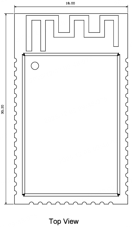
机械尺寸
T3AI-V PCB 尺寸大小:18±0.35 mm (W) × 30.2±0.35 mm (L) × 0.8±0.1 mm (H)。T3AI-V 尺寸如下图所示:
T3AI-V 推荐封装:
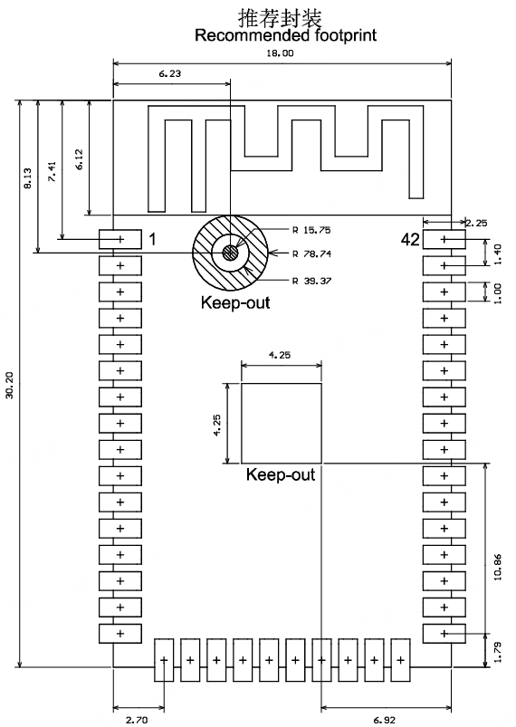
上图中 Keep-out 示意区域,不需要上锡,不要走线。
生产指南
-
涂鸦出厂的可贴可插封装模组根据客户底板设计方案选择组装方式,底板设计为贴片封装时使用 SMT 贴片制程进行生产,如果底板设计为插件封装时使用波峰焊制程进行生产。模组产品拆开包装后建议在 24 小时内完成焊接,否则需放置在湿度不超过 10%RH 的干燥柜内,或重新进行真空包装并记录暴露时间,总暴露时间不超过 168 小时。
- (SMT 制程)SMT 贴片所需仪器或设备:
- 贴片机
- SPI
- 回流焊
- 炉温测试仪
- AOI
- (波峰焊制程)波峰焊所需的仪器或设备:
- 波峰焊设备
- 波峰焊接治具
- 恒温烙铁
- 锡条、锡丝、助焊剂
- 炉温测试仪
- 烘烤所需仪器或设备:
- 柜式烘烤箱
- 防静电耐高温托盘
- 防静电耐高温手套
- (SMT 制程)SMT 贴片所需仪器或设备:
-
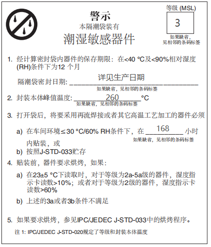
涂鸦出厂的模组存储条件如下:
-
防潮袋必须储存在温度 <40℃、湿度 <90%RH 的环境中。
-
干燥包装的产品,保质期为从包装密封之日起 12 个月的时间。
-
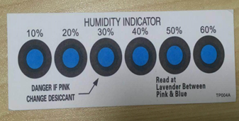
密封包装内装有湿度指示卡:
-
-
涂鸦出厂的模组当出现可能受潮的情况下需要进行烘烤:
- 拆封前发现真空包装袋破损。
- 拆封后发现包装袋内没有湿度指示卡。
- 拆封后如果湿度指示卡读取到 10% 及以上色环变为粉色。
- 拆封后总暴露时间超过 168 小时。
- 从首次密封包装之日起超过 12 个月。
-
烘烤参数如下:
- 烘烤温度:卷盘包装 40℃,湿度小于等于 5%RH。托盘包装 125℃,小于等于 5%RH(耐高温托盘非吸塑盒拖盘)
- 烘烤时间:卷盘包装 168 小时,托盘包装 12 小时。
- 报警温度设定:卷盘包装 50℃,托盘包装 135℃。
- 自然条件下冷却到 36℃ 以下后,即可进行生产。
- 若烘烤后暴露时间大于 168 小时没有使用完,请再次进行烘烤。
- 如果暴露时间超过 168 小时未经过烘烤,不建议使用回流焊或波峰焊接工艺焊接此批次模组。因模组为 3 级湿敏器件超过允许的暴露时间产品可能受潮,进行高温焊接时可能会导致器件失效或焊接不良
-
在整个生产过程中,请对模组进行静电放电(ESD)保护。
-
为了确保产品合格率,建议使用 SPI 和 AOI 测试设备来监控锡膏印刷和贴装品质。
推荐炉温曲线
请根据回流焊接曲线图进行温度设定,峰值温度 245℃,回流焊接温度曲线如下图所示:

- A:温度轴
- B:时间轴
- C:合金液相线温度:217-220℃
- D:升温斜率:1-3℃/S
- E:恒温时间:60-120S,恒温温度:150-200℃
- F:液相线以上时间:50-70S
- G:峰值温度:235-245℃
- H:降温斜率:1-4℃/S
以上推荐曲线以 SAC305 合金焊膏为例。其他合金焊膏请按焊膏规格书推荐炉温曲线设置。
储存条件
模组 MOQ 与包装信息
| 产品型号 | MOQ(pcs) | 出货包装方式 | 每个卷盘存放模组数 | 每箱包装卷盘数 |
|---|---|---|---|---|
| T3AI-V | 3600 | 载带卷盘 | 900 | 4 |
附录:声明
This equipment has been tested and found to comply with the limits for a Class B digital device, pursuant to part 15 of the FCC Rules. These limits are designed to provide reasonable protection against harmful interference in a residential installation. This equipment generates, uses, and can radiate radio frequency energy and, if not installed and used in accordance with the instructions, may cause harmful interference to radio communications. However, there is no guarantee that interference will not occur in a particular installation. If this equipment does cause harmful interference to radio or television reception, which can be determined by turning the equipment off and on, the user is encouraged to try to correct the interference by one or more of the following measures:
- Reorient or relocate the receiving antenna.
- Increase the separation between the equipment and receiver.
- Connect the equipment into an outlet on a circuit different from that to which the receiver is connected.
- Consult the dealer or an experienced radio/TV technician for help.
FCC Caution: Any changes or modifications not expressly approved by the party responsible for compliance could void the user’s authority to operate this device.
This device complies with Part 15 of the FCC Rules. Operation is subject to the following two conditions: (1) This device may not cause harmful interference, and (2) this device must accept any interference received, including interference that may cause undesired operation.
2.2 List of applicable FCC rules
This module has been tested and found to comply with Part 15C, Section 15.247 requirements for Modular Approval.
2.3 Specific Operational Use Conditions- Antenna Placement Within the Host Platform
The module is tested for standalone mobile RF exposure use condition.
- The antenna must be installed such that 20cm is maintained between the antenna and users,
- The transmitter module may not be co-ocated with any other transmitter or antenna.
In the event that these conditions can‘t be met (for example Certain laptop configurations or co-location with another transmitter), then the FCC authorization is no longer considered valid and the FCC ID can't be used on the final product. In these circumstances, the integrator will be responsible for reevaluating the end product (including the transmitter) and obtaining a separate FCC authorization.
2.4 Limited Module Procedures
Not applicable
2.5 Trace Antenna Designs
Not applicable
2.6 RF Exposure Considerations
This device complies with fcc radiation exposure limits set forth for an uncontrolled environment. This equipment should be installed and operated with minimum distance 20cm between the radiator & your body.
2.7 Antenna Type and Gain
The following antennas have been certified for use with this module. Only antennas of the same type with equal or lower gain may also be used with this module. Other types of antennas and/or higher gain antennas may require the additional authorization for operation.
Antenna Specification list below:
| Antenna Type | Antenna Model No. | Maximum Antenna Gain (dBi) | Frequency Range |
|---|---|---|---|
| PCB Antenna | T3AI-V Antenna | 2.56 dBi | 2402~2480 MHz |
2.8 End Product Labeling:
This transmitter module is authorized only for use in device. The final end product must be labeled in a visible area with the following: "Contains Transmitter Module FCC ID: 2ANDL-T3AIV" Or "Contains FCC ID: 2ANDL-T3AIV". The grantee's FCC ID can be used only when all FCC compliance requirements are met. The end product shall bear the following 15.19 statement: This device complies with part 15 of the FCC Rules. Operation is subject to the following two conditions:
(1) This device may not cause harmful interference, and
(2) This device must accept any interference received, including interference that may cause undesired operation.
2.9 Information on Test Modes and Additional Testing Requirements
The module is tested for standalone mobile RF exposure use condition. Any other usage conditions such as co-location with other transmitter(s) or being used in a portable condition will need a separate reassessment through a class Il permissive change application or new certification.
Host manufacturer installed this modular with single modular approval should perform the test of radiated emission and spurious emission according to FCC part 15C, 15.209, 15.207 requirement, only if the test result comply with FCC part 15C 15.209,15.207 requirement, then the host can be sold legally.
2.10 Additional testing, Part 15 Subpart B Disclaimer
This transmitter modular us tested as a subsystem and its certification does not cover the FCC Part 15 Subpart B rules requirement applicable to the final host. The final host will still need to be reassessed for compliance to this portion of rules requirements if applicable.
As long as all conditions above are met, further transmitter test will not be required. However, the OEM integrator is still responsible for testing their end-product for any additional compliance requirements required with this modular installed.
2.11 Manual Information to the End User:
The OEM integrator has to be aware not to provide information to the end user regarding how to install or remove this RF module in the User Manual of the end product which integrates this module. The end user manual shall include all required regulatory information/warning as show in this manual.
The host integrator must follow the integration instructions provided in this document and ensure that the composite-system end product complies with the requirements by a technical assessment or evaluation to the rules and to KDB Publication 996369.
The host integrator installing this module into their product must ensure that the final composite product complies with the requirements by a technical assessment or evaluation to the rules, including the transmitter operation and should refer to guidance in KDB 996369.
OEM/Host Manufacturer Responsibilities:
Manufacturers are ultimately responsible for the compliance of the Host and Module. The final product must be reassessed against all the essential requirements of the FCC rule such as FCC Part 15 Subpart B before it can be placed on the US market. This includes reassessing the transmitter module for compliance with the Radio and EMF essential requirements of the FCC rules. The module must not be incorporated into any other device or system without retesting for compliance as multi-radio and combined equipment.
2.12 How to Mike Changes-Important Note:
In the event that these conditions can‘t be met (for example Certain laptop configurations or co-location with another transmitter), then the FCC authorization is no longer considered valid and the FCC ID can't be used on the final product. In these circumstances, the integrator will be responsible for reevaluating the end product (including the transmitter) and obtaining a separate FCC authorization.
Declaration of Conformity European Notice

Hereby, Hangzhou Tuya Information Technology Co., Ltd declares that this module product is in compliance with essential requirements and other relevant provisions of Directive 2014/53/EU,2011/65/EU. A copy of the Declaration of conformity can be found at https://www.tuya.com.

This product must not be disposed of as normal household waste, in accordance with the EU directive for waste electrical and electronic equipment (WEEE-2012/19/EU). Instead, it should be disposed of by returning it to the point of sale, or to a municipal recycling collection point.
The device could be used with a separation distance of 20cm to the human body.
ISED Statement
This device complies with Innovation, Science and Economic Development Canada's licence-exempt RSSs. Operation is subject to the following two conditions:
(1) This device may not cause interference.
(2) This device must accept any interference, including interference that may cause undesired operation of the device.
Le présent appareil est conforme aux CNR d’Innovation, Sciences et Développement économique Canada applicables aux appareils radio exempts de licence. L’exploitation est autorisée aux deux conditions suivantes:
(1) l’appareil ne doit pas produire de brouillage.
(2) l’utilisateur de l’appareil doit accepter tout brouillage radioélectrique sub i, même si le brouillage est susceptible d’en compromettre le fonctionnement.
Radiation Exposure Statement
This equipment complies with IC radiation exposure limits set forth for an uncontrolled environment. This equipment should be installed and operated with minimum distance 20 cm between the radiator & your body.
Déclaration d’exposition aux radiations:
Cet équipement est conforme aux limites d’exposition aux rayonnements ISED établies pour un environnement non contrôlé. Cet équipement doit être installé et utilisé avec un minimum de 20 cm de distance entre la source de rayonnement et votre corps.
L’appareil peut interrompre automatiquement la transmission en cas d’absence d’informations à transmettre ou de panne opé rationnelle. Notez que ceci n’est pas destiné à interdire la transmission d’informations de contrôle ou de signalisation ou l’utilisation de codes répétitifs lorsque cela est requis par la technologie.
This device is intended only for OEM integrators under the following conditions:
(1) The antenna must be installed such that 20 cm is maintained between the antenna and users.
(2) The transmitter module may not be co-located with any other transmitter or antenna. As long as 2 conditions above are met, further transmitter test will not be required.
However, the OEM integrator is still responsible for testing their end-product for any additional compliance requirements required with this module installed.
Cet appareil est conçu uniquement pour les intégrateurs OEM dans les conditions
suivantes: (Pour utilisation de dispositif module)
(1) L’antenne doit être installée de telle sorte qu’une distance de 20 cm est respectée entre l’antenne et les utilisateurs.
(2) Le module émetteur peut ne pas être coïmplanté avec un autre é metteur ou antenne.
Tant que les 2 conditions ci-dessus sont remplies, des essais supplé mentaires sur l’émetteur neseront pas nécessaires. Toutefois, l’intégrateur OEM est toujours responsable des essais sur son produit final pour toutes exigences de conformité supplémentaires requis pour ce module installé.
IMPORTANT NOTE:
In the event that these conditions can not be met (for example certain laptop configurations or colocation with another transmitter), then the Canada authorization is no longer considered valid and the IC ID can not be used on the final product. In these circumstances, the OEM integrator will be responsible for re-evaluating the end product (including the transmitter) and obtaining a separate Canada authorization.
NOTE IMPORTANTE:
Dans le cas où ces conditions ne peuvent être satisfaites (par exemple pour certaines configurations d’ordinateur mobile ou de certaines co-localisation avec un autre émetteur), l’autorisation du Canada n’est plus considéré comme valide et l’ID IC ne peut pas être utilisé sur le produit final. Dans ces circonstances, l’intégrateur OEM sera chargé de réévaluer le produit final (y compris l’émetteur) et l’obtention d’une autorisation distincte au Canada.
End Product Labeling
This transmitter module is authorized only for use in device where the antenna may be installed such that 20 cm may be maintained between the antenna and users. The final end product must be labeled in a visible area with the following: "Contains IC:23243-T3AIV" .
Plaque signalétique du produit final
Ce module émetteur est autorisé uniquement pour une utilisation dans un dispositif où l’antenne peut être installée de telle sorte qu’une distance de 20cm peut être maintenue entre l’antenne et les utilisateurs. Le produit final doit être étiqueté dans un endroit visible avec l’inscription suivante: "Contient des IC:23243-T3AIV".
Manual Information To the End User
The OEM integrator has to be aware not to provide information to the end user regarding how to install or remove this RF module in the user’s manual of the end product which integrates this module.
The end user manual shall include all required regulatory information/warning as show in this manual.
Manuel d’information à l’utilisateur final
L’intégrateur OEM doit être conscient de ne pas fournir des informations à l’utilisateur final quant à la façon d’installer ou de supprimer ce module RF dans le manuel de l’utilisateur du produit final qui intègre ce module.
Le manuel de l’utilisateur final doit inclure toutes les informations réglementaires requises et avertissements comme indiqué dans ce manuel.
该内容对您有帮助吗?
是意见反馈该内容对您有帮助吗?
是意见反馈