Fully-Functional Smart Indoor Garden
Overview
The peace and refreshing of growing plants come as a welcome relief from the hustle and bustle of city life. However, we sometimes cannot take good care of these beautiful plants due to troubles in life. But don’t worry, the smart indoor garden is a perfect solution for automatic planting. It can take care of our plants even when we are away from home.
In this project, we retrofit an ordinary indoor garden into a fully-functional and IoT-enabled growing system.
Functions
You can empower an indoor garden to have the following functions on a moderate budget.
- Remote control and data monitoring with an app.
- Monitor temperature and humidity, light intensity, soil moisture, and water level.
- Automatic lighting filling, humidifying, heating, ventilating, watering, and water tank filling.
After you have finished the prototype, select an acrylic box to decorate your garden.
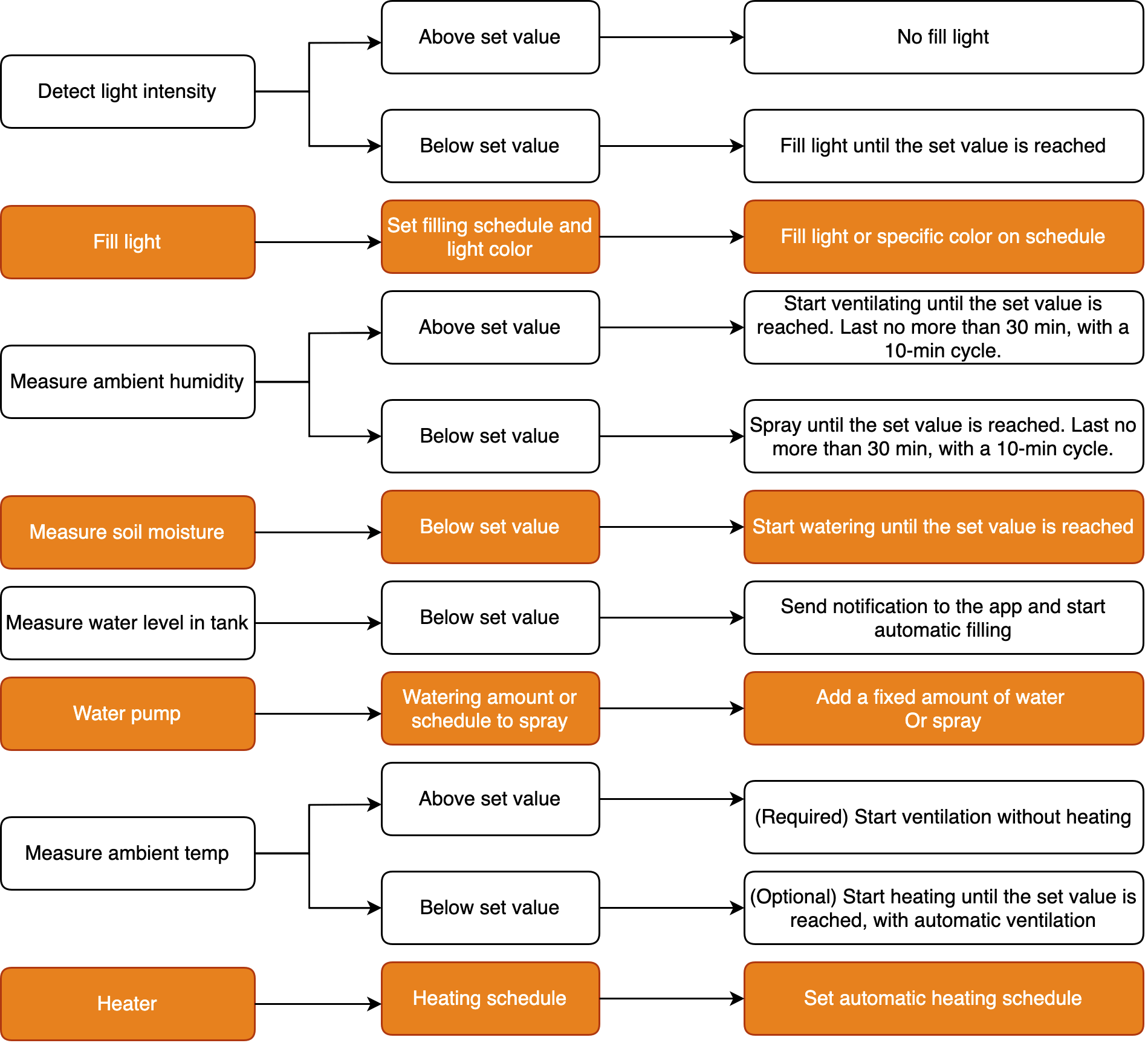
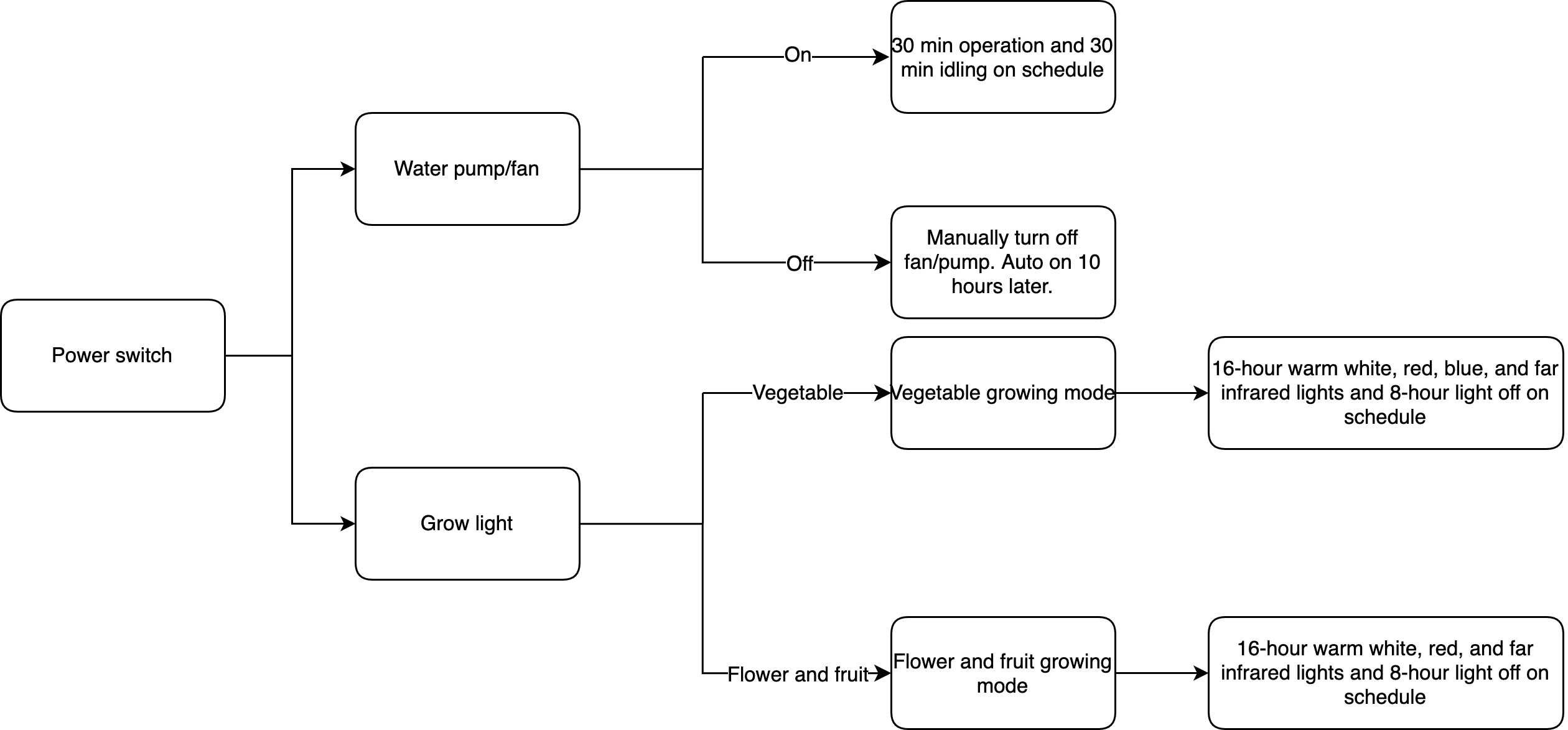
Logic
We divide the functionality into smaller building blocks, as shown in the following figure.
Materials
WB3S network module
Count:1WB3S is a low power Wi-Fi and BLE combo module developed by Tuya Smart. It consists of a highly integrated radio-frequency identification (RFID) chip BK7231T and a few peripheral components, with a built-in Wi-Fi network protocol stack and various library functions.more
Tuya Sandwich DC-DC power supply board
Count:1Provide power supply to other components of the Tuya Sandwich Evaluation Kit.more
Others
Count:1See Step 2: Assemble.more
Steps
Step 1: Prototype
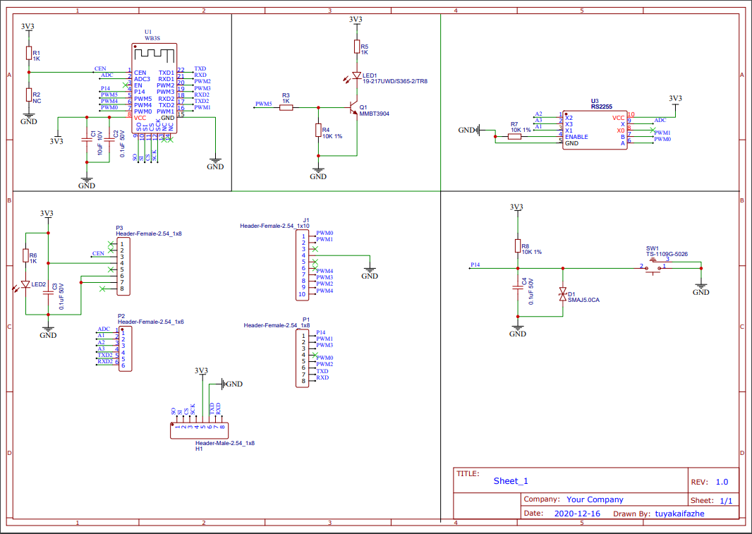
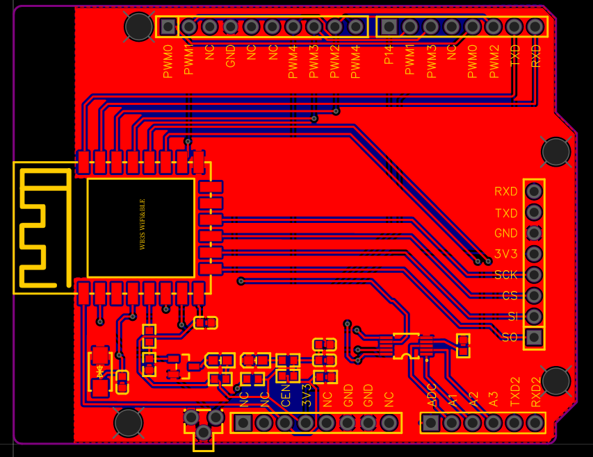
Procedure 1: Modify master control board
To achieve remote control with the Tuya Smart app, we use Tuya’s WB3S network module as the master control. Tuya Sandwich Wi-Fi SoC master control board (WB3S) helps you quickly implement various smart hardware prototypes. This board only has one ADC port so we use a 4-channel analog multiplexer RS2255 to expand more analog channels.
-
Circuit diagram (Download)
-
PCB layout (Download)
RS2255 provides access to three analog channels denoted as A1, A2, and A3.
-
Analog channels
The circuit diagram shows that to read values on A1, A2, and A3, the embedded system must first read the ADC value. PWM0 and PWM1 outputs control RS2255, which correlates with how the ADC is connected to analog channels. See the following table:
Channel PWM0 PWM1 A1 1 0 A2 0 1 A3 1 1
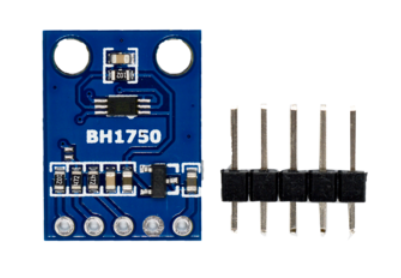
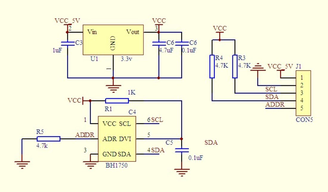
Procedure 2: Detect light intensity
Use a BH1750 light sensor to detect light intensity. BH1750 is a digital ambient light sensor that uses I2C to communicate. BH1750FVI is the digital ambient light sensor IC for the I2C bus interface. It can accurately measure the LUX value of light up to 65535 lx. BH1750 is shown as follows:
-
The circuit diagram of BH1750:
-
Pin configuration:
- VCC: 3–5V power input
- GND: power supply ground
- SCL: I2C clock pin
- SDA: I2C data pin
- ADDR: address pin
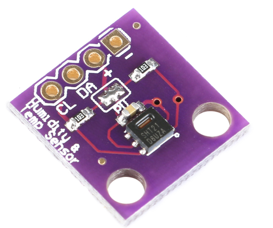
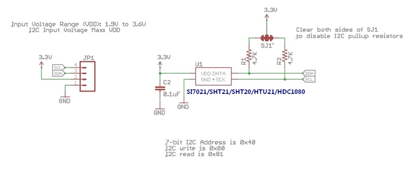
Procedure 3: Measure temperature and humidity
Use an SHT21 humidity and temperature sensor to measure ambient temperature and humidity. SHT21 is fully calibrated and features low power consumption and excellent long-term stability. It communicates with the I2C protocol.
Note: If the SHT21 sensor is not available, you can use the HTU21D sensor alternatively.
-
The circuit diagram of SHT21:
-
Pin configuration:
- VCC: 3.3V power input
- GND: power supply ground
- SCL: I2C clock pin
- SDA: I2C data pin
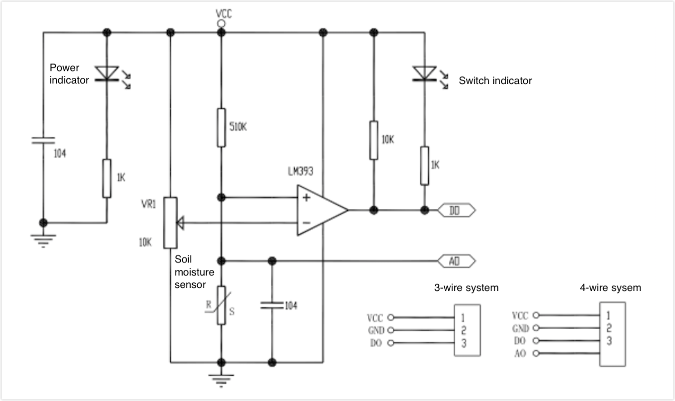
Procedure 4: Measure soil moisture
Use a soil moisture sensor to measure the water content of soil. The surface is nickel-plated and has a wide sensing area, which can improve the conductivity and prevent the problem of rust in contact with the soil. The sensor provides both analog and digital output. The digital output is simple while the analog output is more accurate. You can adjust the sensitivity of the sensor with the help of the potentiometer (blue) on the board of the sensor. The sensor uses an LM393 comparator to compare the soil moisture level with the preset threshold.

-
The circuit diagram of soil moisture sensor:
-
Pin configuration:
- VCC: 3.3–5V power input
- GND: power supply ground
- D0: digital output
- A0: analog output
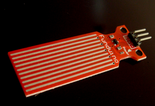
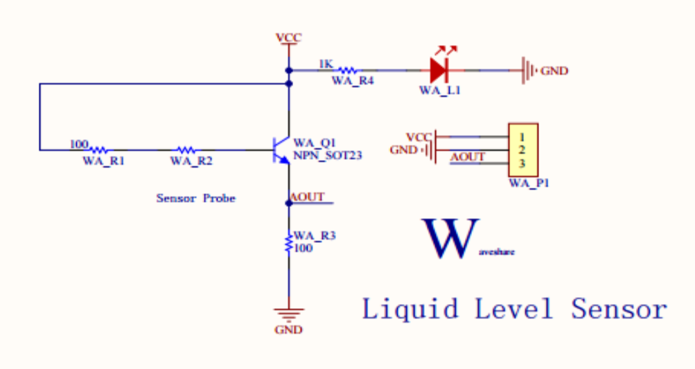
Procedure 5: Measure water tank level
Use a water level sensor to measure the depth of water in the water tank. The water level sensor has high performance and sensitivity with low power consumption. It can easily convert the water volume to an analog signal and the output value can be recognized by microprocessors and thus make the water level alarm happen.
-
The circuit diagram of water level sensor:
-
Pin configuration:
- +: 3–5V power input
- -: power supply ground
- S: analog output
Procedure 6: Fill light
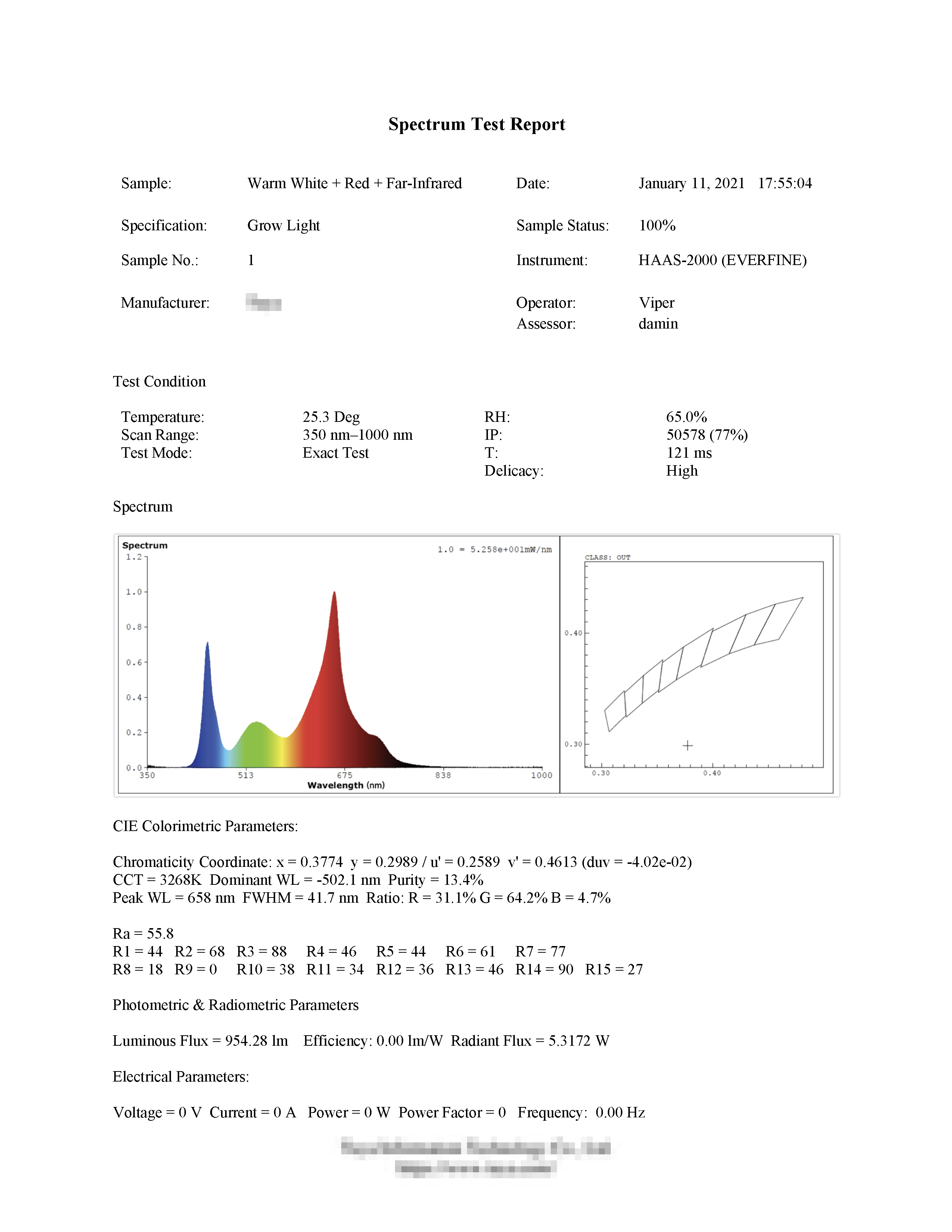
Use the LED grow light on the indoor garden to fill light. The grow light is made of 2835 LED beads. There is a total of 114 beads with four bands of spectrum, namely warm white, red, blue, and far-infrared, and the proportion of each band is 25:9:2:2.
To implement two growing modes for vegetables as well as flowers and fruits, two PWM outputs control the light spectrum. One controls blue light and the other controls warm white, red, and far-infrared lights.

-
Vegetable growing mode:
The grow light board provides warm white, red, blue, and far-infrared lights. The spectrum report is as follows:
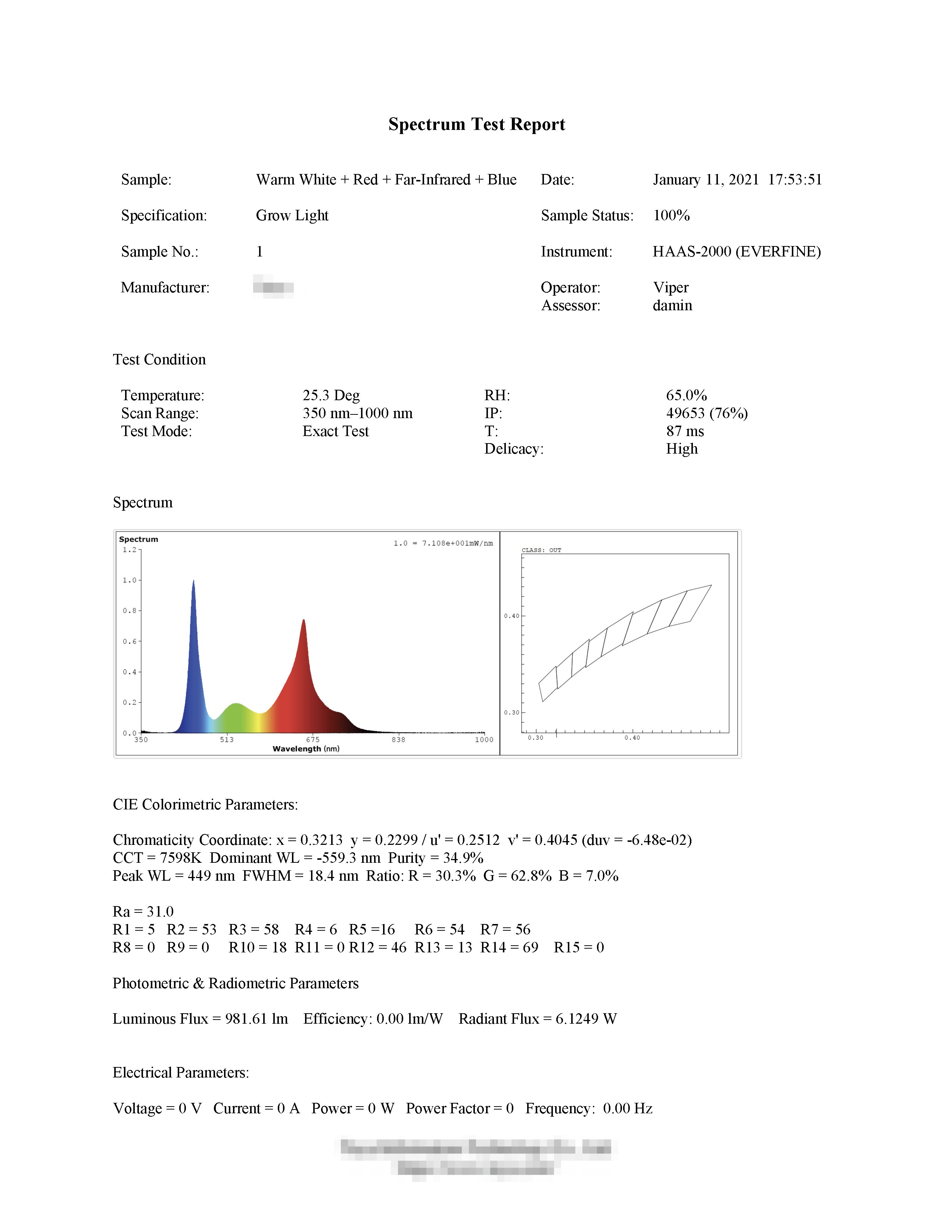

-
Flower and fruit growing mode:
The grow light board provides warm white, red, and far-infrared lights. The spectrum report is as follows:
-
Pin configuration:
- 12V: 12V power input
- PON: PWM input 1
- RON: PWM input 2
- GND: power supply ground
Note that the blue light can only be adjusted when the other PWM signal is outputting. If you do not have a grow light board, you can have two PWM outputs controlling LED strips alternatively.
Procedure 7: Spray
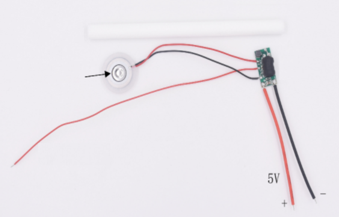
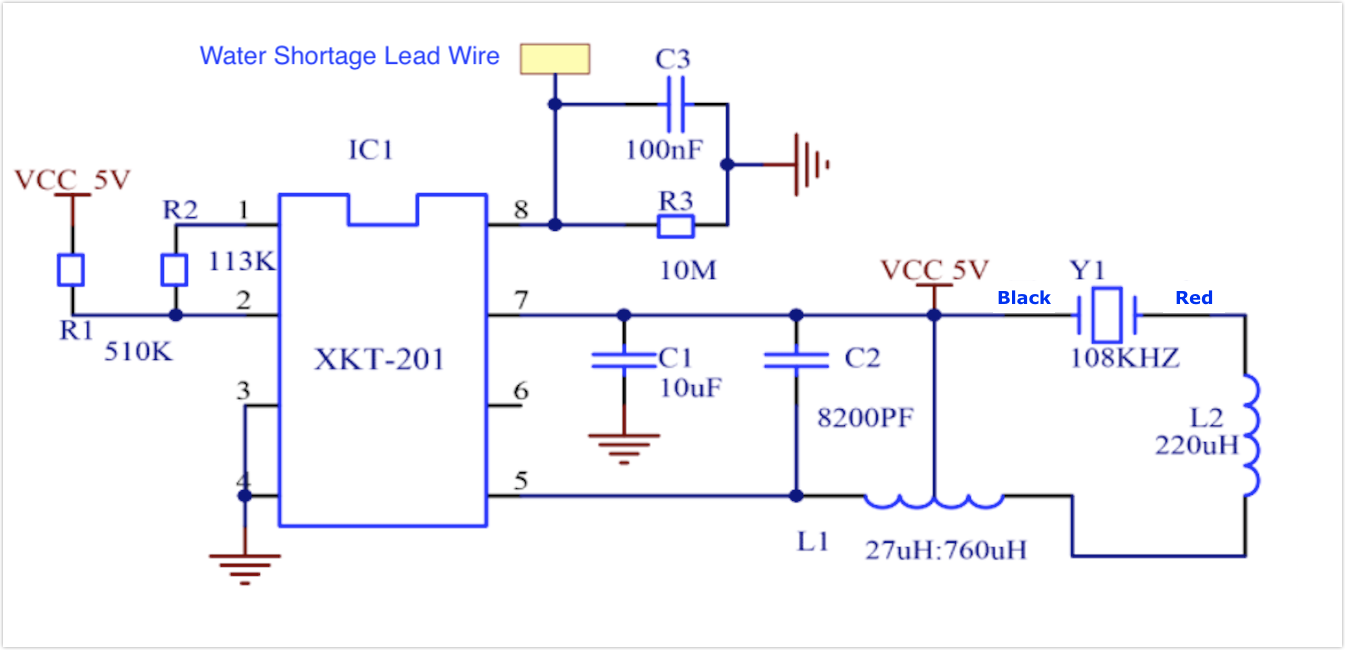
Use a 1-channel relay module to control a 5V mist maker module. The operating frequency of the mist maker chip is 108 kHz. The eighth pin can be used to monitor water level to implement low water cut-off and prevent the atomizer disc from running out of water.
-
The circuit diagram of mist maker module:
-
Pin configuration:
- Red wire: 5V
- Black wire: GND
Procedure 8: Heat
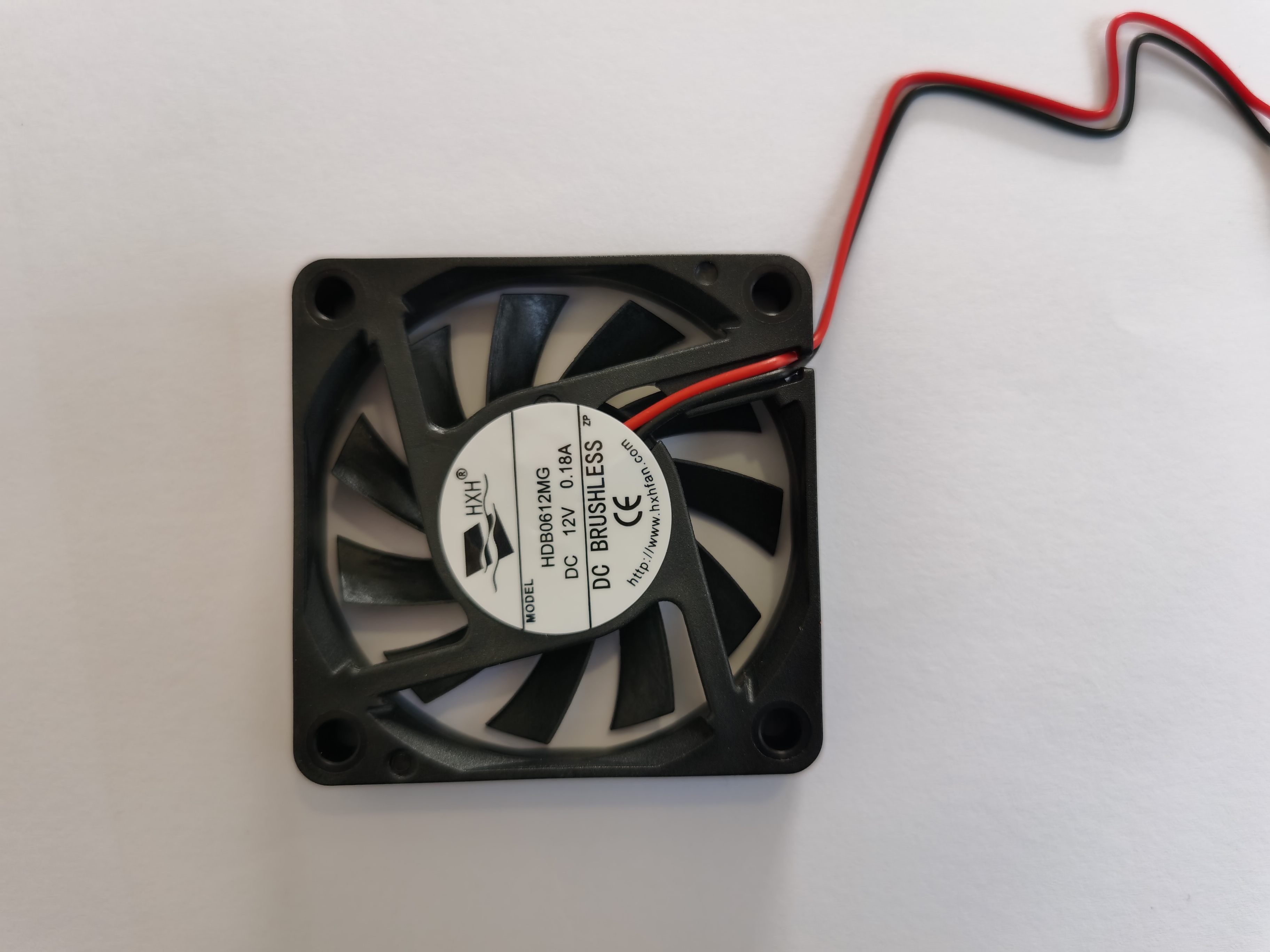
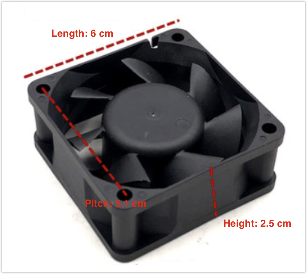
Use a 1-channel relay module to control a 75W far-infrared bulb. Infrared bulbs feature high thermal efficiency, explosion-proof when exposed to water, and quick heat transfer and dissipation. Importantly, it can work effectively in humid environments. You can use a cooling fan as needed.

(Optional) Cooling fan: Use the cooling fan (12V DC 0.18A) installed on the indoor garden. The fan and infrared bulb are connected in parallel through the 220V AC to 12V DC power supply transformer, which is controlled by the relay module.
Procedure 9: Ventilate
Use a 1-channel relay module to control two high-speed cooling fans (12V 0.5A). Ventilation can reduce ambient temperature and humidity to pollinate plants.
Procedure 10: Fill water tank
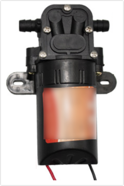
Use a 1-channel relay module to control a 12V water pump. You can choose a water supply as needed or change the water pump to a 12V water solenoid valve.
-
Power: 24W
-
Flow rate: 5 l/min
-
Inlet water pressure: 0.48 MPa
Procedure 3: Water
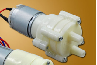
Use a 1-channel relay module to control two 12V DC diaphragm pumps. The water is pumped and applied to the soil.
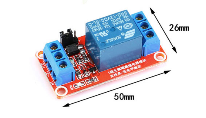
Procedure 12: Why do we use relay modules?
Relay modules are typically used to switch devices that use a higher voltage than what most micro-controllers can handle.
You can use two 1-channel relay modules and one 4-channel relay module to implement automatic spraying, heating, water tank filling, ventilating, and watering.
-
1-channel relay module
-
4-channel relay module

-
Relay pin
Notation Description DC+ Positive power supply (VCC). DC- Negative power supply (GND). IN or INx Input control signal. NO or NOx Normally open high voltage terminal. COM or COMx Common terminal. NC or NCx Normally closed high voltage terminal.
Procedure 13: Select indoor garden
Select a simple traditional indoor garden for retrofitting.
We prepare a traditional indoor garden, with a grow light board and large soil container.
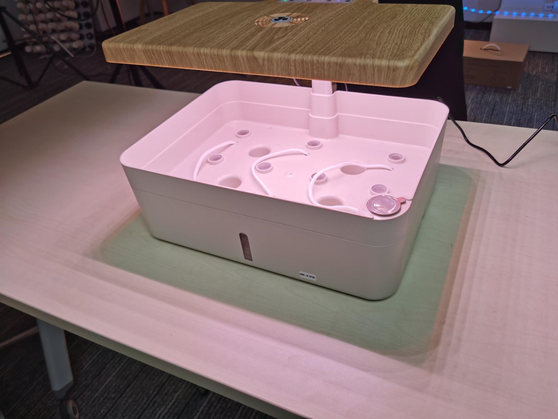
This garden has the following functions:
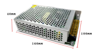
Procedure 14: Garden power supply
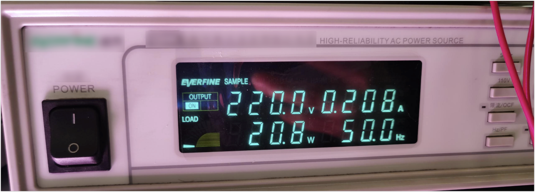
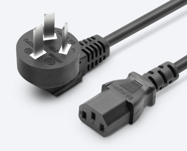
The garden needs four kinds of power supplies, namely 220V AC, 12V DC, 5V DC, and 3.3V DC. To achieve this, we use the following solutions:
-
220V AC: Power supply from 220V/50 Hz power grid.
-
12V DC: Connect an S-120-12 switching power supply to 220V AC power grid.
The 12V cooling fan is linked with the infrared bulb. The infrared bulb is connected to 220V AC power supply. An isolated switching power supply module (12V 400 mA) produces 12V DC for the cooling fan.

-
5V DC: Supply the relay module and ultrasonic mist maker.
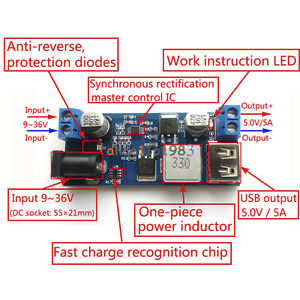
Module specification:
- Input voltage: 9V–36V DC
- Output voltage: 5.2V/5A/25W
- Inputting different voltage will output different power:
- 9–24V DC, output 5.2V/6A/30W.
- 24–32V DC, output 5.2V/5A/25W.
- 32–36V DC, output 5.2V/3.5A/18W.
-
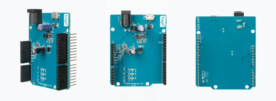
3.3V DC: Supply from Tuya Sandwich DC-DC power board. This power supply board is equipped with dual power jacks, accepting either 12V DC or 5V DC power supply.
-
When 12V DC is input, two SY8012B chips work to provide 12V, 5V, and 3.3V DC supply for other components on the board.
-
When 5V DC is input, one SY8012B chip works to provide 5V and 3.3V DC supply for other components on the board.
-
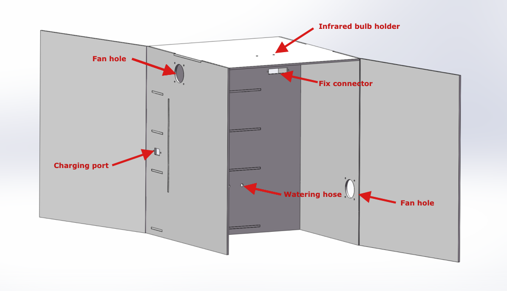
Procedure 15: Design acrylic box
We design an acrylic box with Adobe AutoCAD. Things to note:
- Pot size
- Component size and layout
- Fix hole position
- Screw hole for wiring
The following figures show the component layout for your reference. You can modify and redesign to suit your needs. Download 2D drawings.
-
Front view:
-
Rear view:
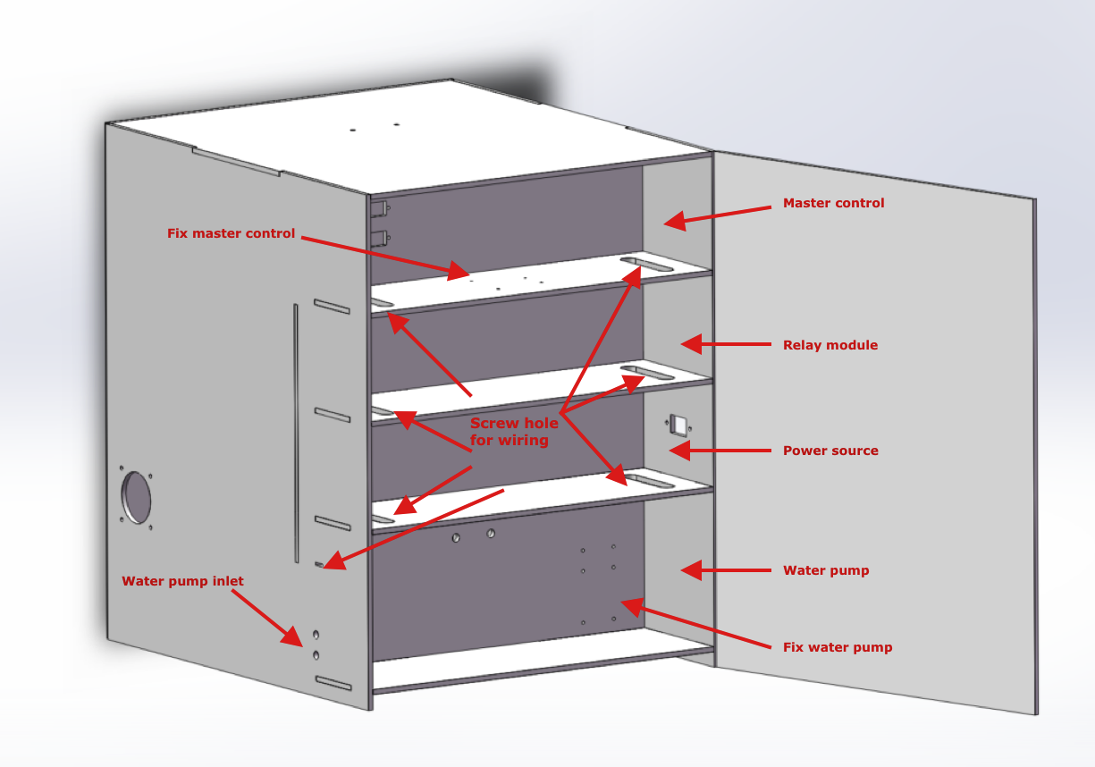
-
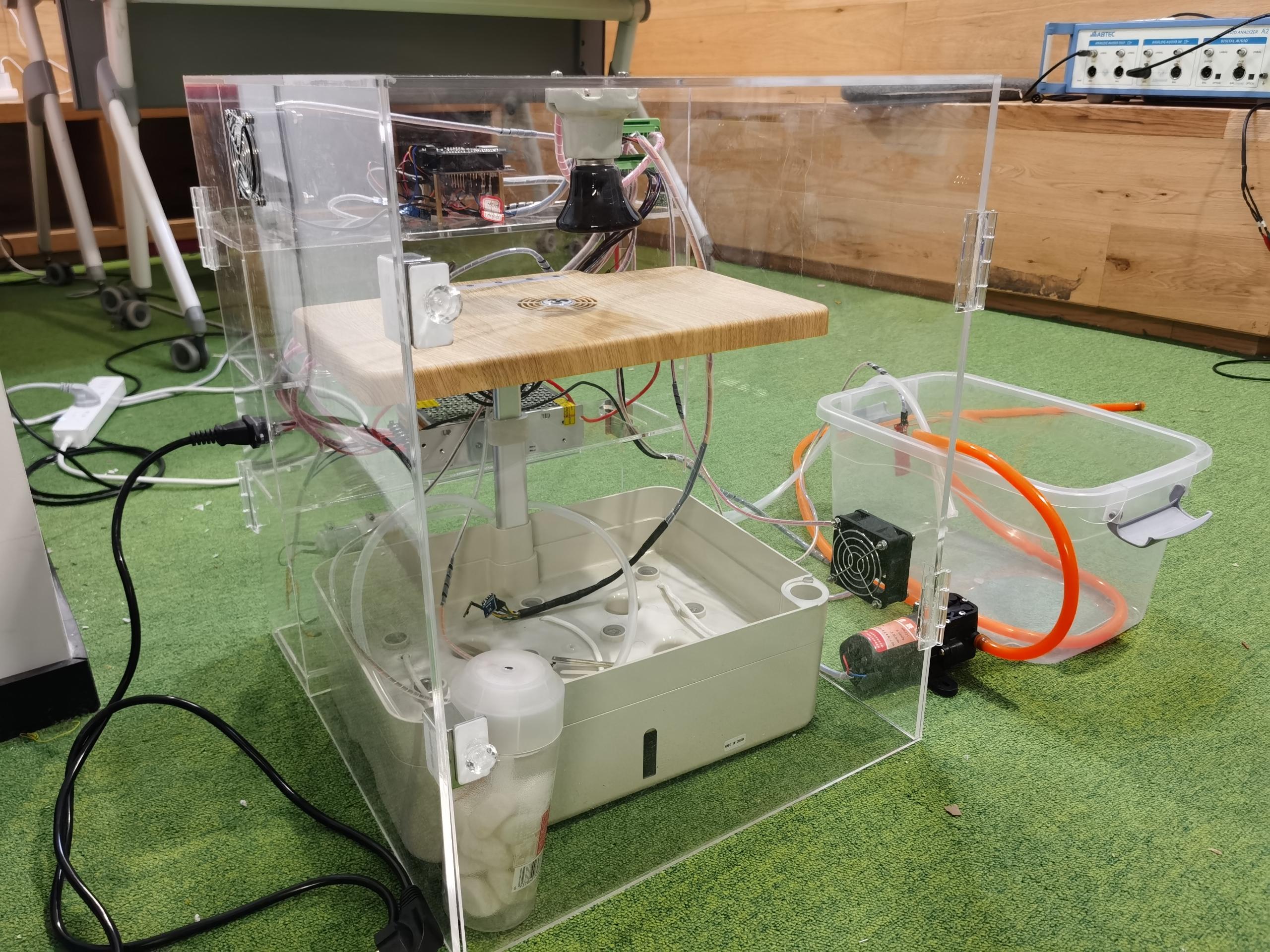
Step 2: Assemble
Procedure 1: Prepare materials
Prepare the following components and supplies.
Item Specification Quantity Tuya Sandwich DC-DC power supply board Default 1 Tuya Sandwich Wi-Fi board Made by Tuya 1 Tuya USB to UART adapter Default 2 1007 26 AWG red hook-up wire 10m 1 1007 26 AWG yellow hook-up wire 10m 1 1007 26 AWG black hook-up wire 10m 1 Heat shrink tubing Φ2/3/4/5/6/8.0 mm 1 40-pin jumper wire Male to male 3 40-pin jumper wire Male to female 3 40-pin jumper wire Female to female 3 Red and black zip cord RVB2 × 0.5 mm² 10 220V to 12V AC-DC buck converter Output 12V 400 mA 1 Computer power cord 3 × 0.5 mm² 1 AC power entry connector 3-pin 1 Relay module 4-channel, 5V 1 Relay module 1-channel, 5V 1 Water level sensor Default 1 Light sensor BH1750 1 Soil moisture sensor Default 1 HTU21 humidity and temperature sensor HTU21D 1 Screwless terminal blocks 12-pin 2 Ceramic lamp holder Default 1 Ceramic infrared heat bulb 75W 1 Spray hose (for filling water tank) 1m 2 Pressure water pump (for filling water tank) DP-521 1 Silicone tubing hose (for watering) Default 2 Small water pump (for watering) Default 2 12V to 5V 5A DC-DC buck converter Default 1 12V DC high-speed cooling fan 60 × 60 × 25 mm 2 220V to 12V 10A switching power supply 12V 10A 1 Mist maker module Default 1 Acrylic adhesive Default 1 Magnetic cabinet door catch 5-pack, no drilling 1 Spiral wrap 10 mm White 1 Spiral wrap 8 mm White 1 Spiral wrap 6 mm White 1 Spiral wrap 4 mm White 1 Nylon spacer (for installing power supply board) M3 × 0.5 × 6 mm 1 M3 nut 304 stainless steel (50 pieces) 1 M3 screw M3 × 16 mm (100 pieces) 1 M4 screw M4 × 40 mm (20 pieces) 1 M3 brass standoff M3 × 40 mm (20 pieces) 1 Countersunk bolts screw nut kit 304 stainless steel (M3, M4, and M5) 1 Transparent acrylic sheet Custom 1 Transparent acrylic hinge 65 × 42 mm (10 pieces) 4 Traditional indoor garden Soil culture 1 Procedure 2: Assemble acrylic box
Cut the acrylic sheet according to drawings. Assemble acrylic components with adhesive.
Procedure 3: Wiring
Procedure 4: Install components
Things to note:
- Component position.
- The upper vent is for the air inlet and the lower vent is for the air outlet.
- Wire usage and length.
- Light sensor position.
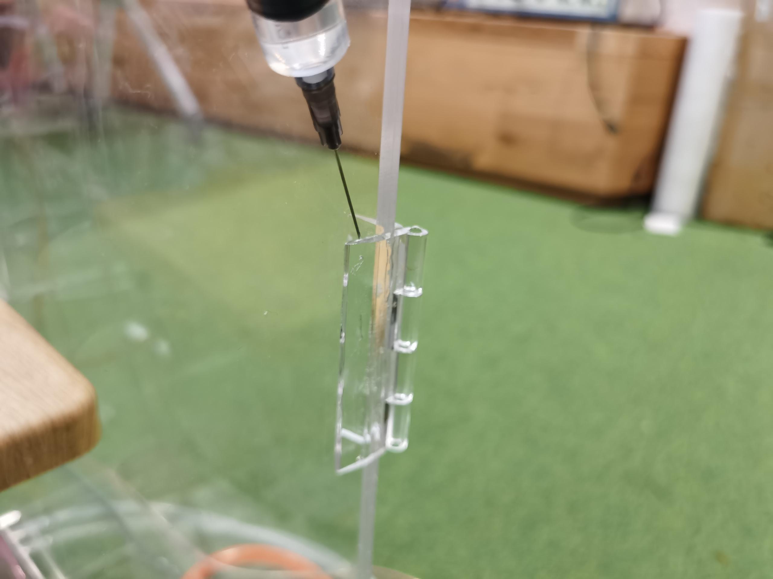
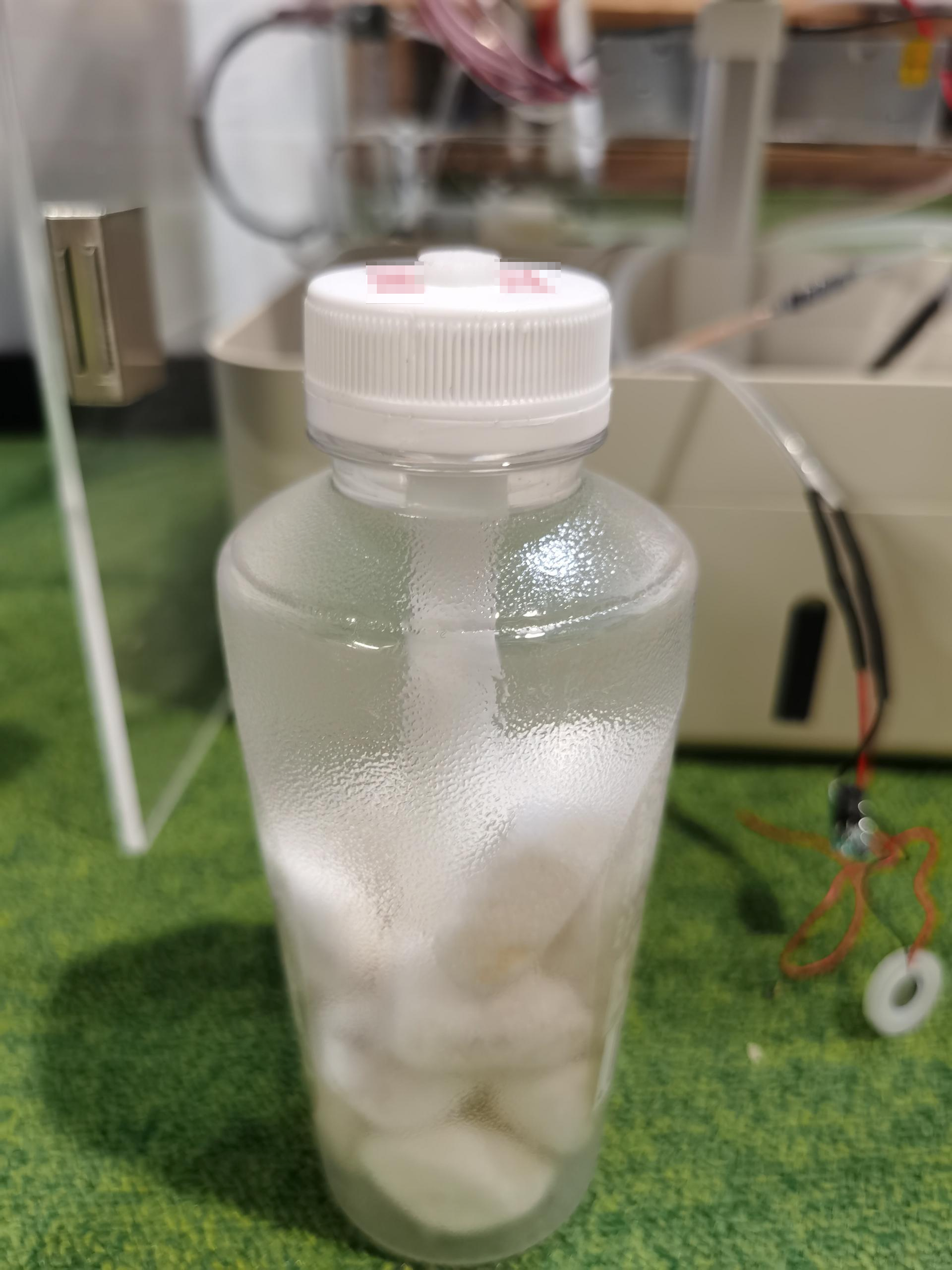
Procedure 5: Make mist maker
-
Find a bottle with a lid.
-
Fix the absorbent cotton.
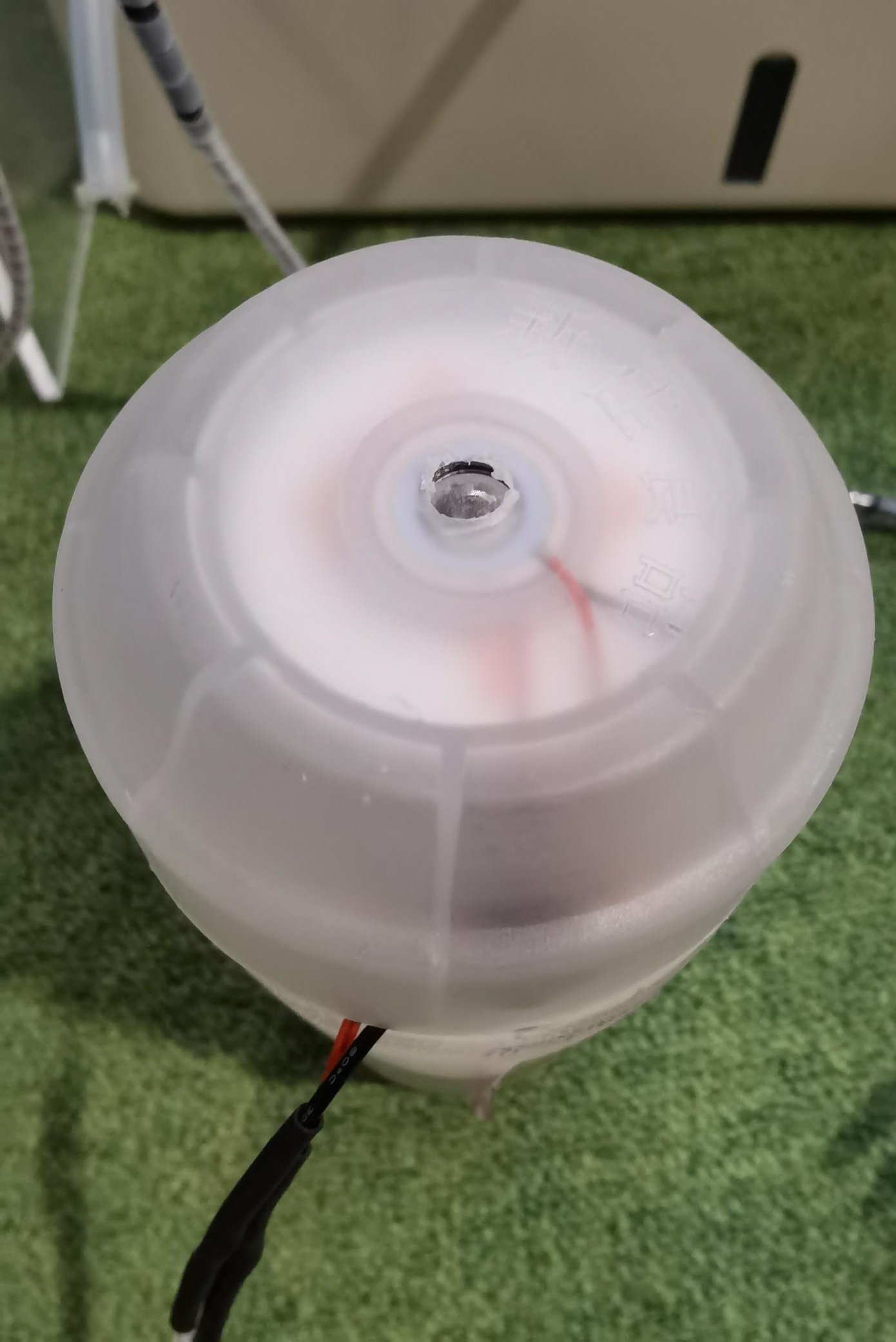
Drill a hole in the lid with an appropriate diameter to fix the absorbent cotton. Put some sand or small stones to fix the bottom of the cotton.
-
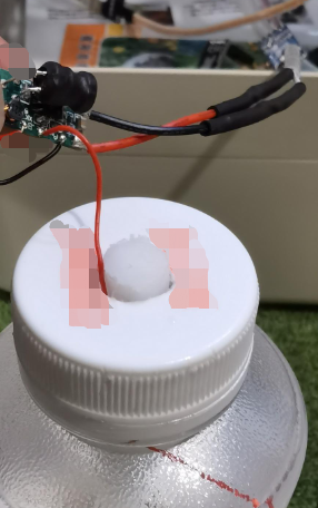
Insert the water level sensing wire into the bottle through the lid hole.
-
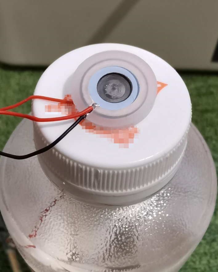
Fix the mist maker.
-
Place the mist maker on the lid as shown in the figure.
-
Screw the lid back on but not too tight. Otherwise, the mist cannot be produced. If a bottle is not available, you can fix the mist maker with hot glue.
-
Procedure 6: Finish assembly
Place components into the box and organize wires.
Step 3: Create
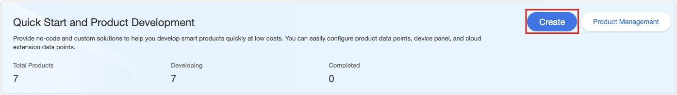
To proceed with TuyaOS development, you need to create an indoor garden product on the Tuya IoT Platform and then get the SDK. This product represents all the IoT functions of a smart garden, including product authorization and configuration, which builds the communication between the garden and the Tuya IoT Platform. This section describes how to create a smart indoor garden on the Tuya IoT Platform. For more information, see Create Products.
-
Log in to the Tuya IoT Platform, and click Create.
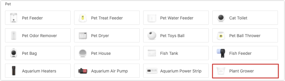
-
Select Small Home Appliances > Plant Grower.
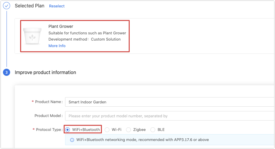
-
Click Custom Solution > Plant Grower. Enter a product name, select WiFi+Bluetooth for protocol type, and click Create Product at the bottom of this page.
-
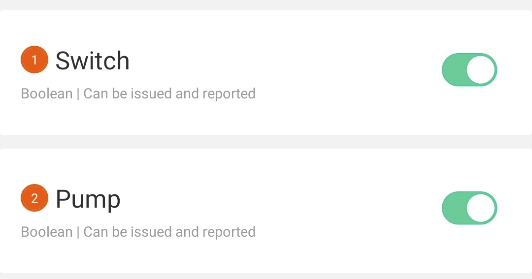
In Create Standard Functions, select Switch, Pump, Current Temperature, Current Humidity, Countdown, Left Time, and Fault.

-
(Optional) To implement the non-standard functions of a smart garden, you need to customize some functions.
-
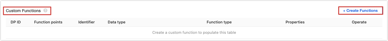
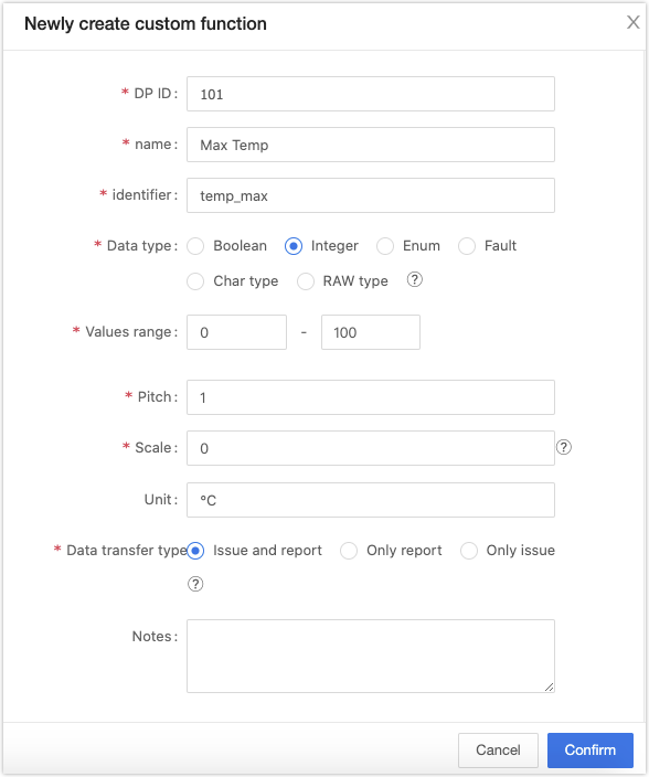
Find Custom Functions and click Create Functions. Set properties for a custom function.
-
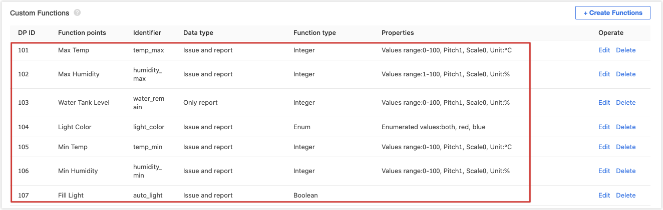
To set the temperature and humidity range, add four integer data points (DPs), namely Max Temp, Min Temp, Max Humidity, and Min Humidity.
-
To transmit the data of water tank level to the cloud, add the integer DP of Water Tank Level.
-
To control grow light color, add the enum DP of Light Color.
-
To switch between scheduled and auto light filling, add the boolean DP of Fill Light.
-
-
When you complete function definition, click Device Panel to select a favorite app control panel. It is recommended to select the Debug Panel to suit your debugging needs.
You have finished creating a product on the Tuya IoT Platform. It is ready to proceed with embedded system development.
-
Step 4: Code
The embedded code is based on the BK7231 chipset and developed with Tuya’s general Wi-Fi SDK. You can get the environment variables from the demo routine pulled from Tuya’s GitHub repository or download the demo routine that includes SDK environment variables. We get the SDK with method 1.
-
Method 1: The BK7231T SDK in GitHub repository
ty_iot_wf_bt_sdk_bk7231t. -
Method 2: The garden demo in GitHub.
Procedure 1: Entry to application
Clone the repository to create a local copy on your computer. Open the
appsfolder that stores demo code. In this folder, create a new folder namedbk7231t_plant_grow_mach_demoto store demo-related source files, header files, and compiled files.If this is your first time to deal with BK7231 development, we recommend that you find
tuya_device.candtuya_device.hin thesrcandincludefolder respectively in thebk7231t_bl0937_1_plug_demoand copy them to this newly created folder.Open
tuya_device.cand find thedevice_initfunction.OPERATE_RET device_init(VOID) { OPERATE_RET op_ret = OPRT_OK; TY_IOT_CBS_S wf_cbs = { status_changed_cb,\ gw_ug_inform_cb,\ gw_reset_cb,\ dev_obj_dp_cb,\ dev_raw_dp_cb,\ dev_dp_query_cb,\ NULL, }; op_ret = tuya_iot_wf_soc_dev_init_param(hw_get_wifi_mode(),WF_START_SMART_FIRST,\ &wf_cbs,NULL,PRODECT_KEY,DEV_SW_VERSION); if(OPRT_OK != op_ret) { PR_ERR("tuya_iot_wf_soc_dev_init_param error,err_num:%d",op_ret); return op_ret; } op_ret = tuya_iot_reg_get_wf_nw_stat_cb(wf_nw_status_cb); if(OPRT_OK != op_ret) { PR_ERR("tuya_iot_reg_get_wf_nw_stat_cb is error,err_num:%d",op_ret); return op_ret; } op_ret= app_dltj_init(APP_DLTJ_NORMAL); if(OPRT_OK != op_ret) { PR_ERR("dltj init err!"); return op_ret; } op_ret = app_switch_init(APP_SW_MODE_NORMAL); if(op_ret != OPRT_OK) { return op_ret; } return op_ret; }In the development environment for the BK7231T chipset, the
device_initfunction is the entry to the application code. When the device is powered on, the BK7231T adaptation layer runs the initialization code and then calls this function to initialize the application layer. This function deals with the followings:-
Call
tuya_iot_wf_soc_dev_init_param()for SDK initialization to configure working mode and pairing mode, register callback functions, and save the firmware key and PID.TY_IOT_CBS_S wf_cbs = { status_changed_cb,\ gw_ug_inform_cb,\ gw_reset_cb,\ dev_obj_dp_cb,\ dev_raw_dp_cb,\ dev_dp_query_cb,\ NULL, }; op_ret = tuya_iot_wf_soc_dev_init_param(hw_get_wifi_mode(),WF_START_SMART_FIRST,\ &wf_cbs,NULL,PRODECT_KEY,DEV_SW_VERSION); if(OPRT_OK != op_ret) { PR_ERR("tuya_iot_wf_soc_dev_init_param error,err_num:%d",op_ret); return op_ret; } -
Call
tuya_iot_reg_get_wf_nw_stat_cb()to register callback of device network status.op_ret = tuya_iot_reg_get_wf_nw_stat_cb(wf_nw_status_cb); if(OPRT_OK != op_ret) { PR_ERR("tuya_iot_reg_get_wf_nw_stat_cb is error,err_num:%d",op_ret); return op_ret; } -
Call initialization function in the application layer.
op_ret= app_dltj_init(APP_DLTJ_NORMAL);
if(OPRT_OK != op_ret) {
    PR_ERR("dltj init err!");
    return op_ret;
}

op_ret = app_switch_init(APP_SW_MODE_NORMAL);
if(op_ret != OPRT_OK) {
    return op_ret;
}
Because
tuya_device.cis borrowed from another demo, we need to implement an application initialization function for this demo. Createapp_plant.cand its header file and implementapp_plant_init()function that is called indevice_init.Procedure 2: Application architecture
The application code is implemented in three layers.
- The bottom layer has the sensor driver code and packages interfaces of sensor initialization and data collection.
- The second layer has part of control logic code and calls sensor driver interfaces to implement the control logic of each component. This layer packages interfaces of polling data processing.
- The first layer creates application tasks to call the interface in the second layer, processes DP data transmission, and accepts parsing.
app_plant.cimplements the first layer.-
app_plant_init()calls device initialization interface packaged in the second layer and creates application tasks.OPERATE_RET app_plant_init(IN APP_PLANT_MODE mode) { OPERATE_RET op_ret = OPRT_OK; if(APP_PLANT_NORMAL == mode) { // Initialize I/O, sensors, PWM, and more plant_device_init(); // Create data collection tasks for I2C sensors xTaskCreate(sensor_data_get_iic_theard,"thread_data_get_iic",512,NULL,TRD_PRIO_3,NULL); // Create data collection tasks for ADC sensors xTaskCreate(sensor_data_get_adc_theard,"thread_data_get_adc",512,NULL,TRD_PRIO_4,NULL); // Create data processing tasks xTaskCreate(sensor_data_deal_theard,"thread_data_deal",512,NULL,TRD_PRIO_4,NULL); // Create scheduled tasks for DP data reporting xTaskCreate(sensor_data_report_theard,"thread_data_report",512,NULL,TRD_PRIO_4,NULL); }else { // Non-production test mode } return op_ret; } -
app_report_all_dp_status()reports all DP data:VOID app_report_all_dp_status(VOID) { OPERATE_RET op_ret = OPRT_OK; INT_T dp_cnt = 0; dp_cnt = 12; TY_OBJ_DP_S *dp_arr = (TY_OBJ_DP_S *)Malloc(dp_cnt*SIZEOF(TY_OBJ_DP_S)); if(NULL == dp_arr) { PR_ERR("malloc failed"); return; } memset(dp_arr, 0, dp_cnt*SIZEOF(TY_OBJ_DP_S)); dp_arr[0].dpid = DPID_SWITCH_P; dp_arr[0].type = PROP_BOOL; dp_arr[0].time_stamp = 0; dp_arr[0].value.dp_value = plant_ctrl_data.Switch; ...... op_ret = dev_report_dp_json_async(NULL,dp_arr,dp_cnt); Free(dp_arr); if(OPRT_OK != op_ret) { PR_ERR("dev_report_dp_json_async relay_config data error,err_num",op_ret); } PR_DEBUG("dp_query report_all_dp_data"); return; } -
Task function.
In a task,
plant_get_iic_sensor_data(),plant_get_adc_sensor_data(),plant_ctrl_handle(), andplant_ctrl_all_off()are called in a loop. These interfaces are from the second layer and implemented inplant_control.c.STATIC VOID sensor_data_get_iic_theard(PVOID_T pArg) { while(1) { PR_DEBUG("plant_get_i2c_sensor_data"); vTaskDelay(TASKDELAY_SEC); if(TRUE == plant_ctrl_data.Switch) { plant_get_iic_sensor_data(); } } } STATIC VOID sensor_data_get_adc_theard(PVOID_T pArg) { while(1) { PR_DEBUG("plant_get_adc_sensor_data"); vTaskDelay(TASKDELAY_SEC*2); if(TRUE == plant_ctrl_data.Switch) { plant_get_adc_sensor_data(); } } } STATIC VOID sensor_data_deal_theard(PVOID_T pArg) { while(1) { vTaskDelay(TASKDELAY_SEC); if(TRUE == plant_ctrl_data.Switch) { plant_ctrl_handle(); }else { plant_ctrl_all_off(); } } } STATIC VOID sensor_data_report_theard(PVOID_T pArg) { while(1) { vTaskDelay(TASKDELAY_SEC*5); app_report_all_dp_status(); } } -
deal_dp_proc()processes the received DP data according to the DP ID.VOID deal_dp_proc(IN CONST TY_OBJ_DP_S *root) { UCHAR_T dpid; dpid = root->dpid; PR_DEBUG("dpid:%d",dpid); switch (dpid) { case DPID_SWITCH_P: PR_DEBUG("set switch:%d",root->value.dp_bool); plant_ctrl_data.Switch = root->value.dp_bool; break; case DPID_PUMP: PR_DEBUG("set pump:%d",root->value.dp_bool); plant_ctrl_data.Pump = root->value.dp_bool; break; ...... default: break; } return; }
We have built the application architecture. And next, we need to implement interfaces in the second layer, which are placed in
plant_control.c. The following procedures describe control logic in terms of temperature and humidity, light, and soil moisture.Procedure 3: Temperature and humidity
To control temperature and humidity, first we must collect data. The SHT21 sensor collects temperature and humidity data. It communicates with the I2C protocol. We write sensor driver code based on the SHT21 technical manual. When the driver code is completed, we package interfaces of sensor initialization, data collection, and data conversion.
All the SHT21 driver and external interfaces are implemented in
sht21.c. The packaged external interfaces are called fromplant_control.c.-
tuya_sht21_init(sht21_init_t* param)initializes the sensor. The request parameter is a pointer to a struct that contains information about SDA and SCL I/O pins and resolution.typedef struct { UCHAR_T SDA_PIN; ///< SDA pin UCHAR_T SCL_PIN; ///< SCL pin sht21_resolution_t RESOLUTION; }sht21_init_t; -
Define struct variables in
plant_control.cand callplant_device_init()to initialize the sensor.#define IIC_SDA_PIN (6) #define IIC_SCL_PIN (7) STATIC sht21_init_t sht21_int_param = {IIC_SDA_PIN, IIC_SCL_PIN, SHT2x_RES_10_13BIT}; VOID plant_device_init(VOID) { // SHT21 IIC driver init tuya_sht21_init(&sht21_int_param); } -
After initialization, the sensor can provide ambient temperature and humidity values. Because the garden requires continuous ambient parameters, the interface to get sensing data must be invoked accordingly. In the above procedure, one of task functions in
app_plant.ccallsplant_get_iic_sensor_data()in a loop inplant_control.c. Therefore, we need to call sensor data collection interfacetuya_sht21_measure()and computing interfacetuya_sht21_cal_RH(). The parameters of these two interfaces are enum values to get temperature or humidity.VOID plant_get_iic_sensor_data(VOID) { SHORT_T hum; SHORT_T temp; tuya_sht21_init(&sht21_int_param); hum = tuya_sht21_measure(HUMIDITY); device_data.humidity = tuya_sht21_cal_RH(hum); if(device_data.humidity > 0){ // Remove invalid humidity values less than 0 plant_report_data.Humidity_current = (UCHAR_T)device_data.humidity; PR_NOTICE("humidity = %d",plant_report_data.Humidity_current); } temp = tuya_sht21_measure(TEMP); device_data.temperature = tuya_sht21_cal_temperature(temp); plant_report_data.Temp_current = (UCHAR_T)device_data.temperature; PR_NOTICE("tempre = %d",plant_report_data.Temp_current); } -
Compare the ambient temperature and humidity with a threshold value. We have created four DPs of max and min temperature and humidity on the Tuya IoT Platform, so we can set threshold values with an app and send them to the device through the cloud. The
deal_dp_proc()function inapp_plant.cprocesses DP data.VOID deal_dp_proc(IN CONST TY_OBJ_DP_S *root) { UCHAR_T dpid; dpid = root->dpid; PR_DEBUG("dpid:%d",dpid); switch (dpid) { ...... case DPID_TEMP_MAX: PR_DEBUG("set temp max:%d",root->value.dp_value); plant_ctrl_data.Temp_max = root->value.dp_value; break; case DPID_HUMIDITY_MAX: PR_DEBUG("set humidity max:%d",root->value.dp_value); plant_ctrl_data.Humidity_max = root->value.dp_value; break; case DPID_TEMP_MIN: PR_DEBUG("set temp min:%d",root->value.dp_value); plant_ctrl_data.Temp_min = root->value.dp_value; break; case DPID_HUMIDITY_MIN: PR_DEBUG("set humidity min:%d",root->value.dp_value); plant_ctrl_data.Humidity_min = root->value.dp_value; break; ...... default: break; } return; } -
A task for data comparison and I/O device control is created in
app_plant.c. It callsplant_ctrl_handle()function ofplant.control.cin a loop. All control logic is specified inplant_ctrl_handle(). To adjust the temperature and humidity, we use a mist maker, infrared bulb, and cooling fan, which are switched on/off through relay modules.tuya_gpio_inout_set()andtuya_gpio_write()interfaces packaged in this SDK control I/O outputs. The code is as follows:#define HUMIDIFIER_PORT (24) #define HUMIDIFIER_LEVEL LOW #define HEATING_ROD_PORT (20) #define HEATING_ROD_LEVEL LOW #define COOL_DOWN_FAN_PORT (21) #define COOL_DOWN_FAN_LEVEL LOW STATIC VOID __ctrl_gpio_init(CONST TY_GPIO_PORT_E port, CONST BOOL_T high) { // Set I/O pin to output mode tuya_gpio_inout_set(port, FALSE); // Set I/O level tuya_gpio_write(port, high); } VOID plant_device_init(VOID) { // SHT21 IIC driver init tuya_sht21_init(&sht21_int_param); // gpio init __ctrl_gpio_init(HUMIDIFIER_PORT, HUMIDIFIER_LEVEL); __ctrl_gpio_init(COOL_DOWN_FAN_PORT, COOL_DOWN_FAN_LEVEL); __ctrl_gpio_init(HEATING_ROD_PORT, HEATING_ROD_LEVEL); } STATIC VOID __passive_ctrl_module_temp_humidity(VOID) { if(device_data.humidity < plant_ctrl_data.Humidity_min) { tuya_gpio_write(HUMIDIFIER_PORT, !HUMIDIFIER_LEVEL); }else { tuya_gpio_write(HUMIDIFIER_PORT, HUMIDIFIER_LEVEL); } if(device_data.temperature < plant_ctrl_data.Temp_min) { tuya_gpio_write(HEATING_ROD_PORT, !HEATING_ROD_LEVEL); }else { tuya_gpio_write(HEATING_ROD_PORT, HEATING_ROD_LEVEL); } if((device_data.temperature > plant_ctrl_data.Temp_max)||(device_data.humidity > plant_ctrl_data.Humidity_max)) { tuya_gpio_write(COOL_DOWN_FAN_PORT,!COOL_DOWN_FAN_LEVEL); }else { tuya_gpio_write(COOL_DOWN_FAN_PORT,COOL_DOWN_FAN_LEVEL); } } VOID plant_ctrl_handle(VOID) { PR_DEBUG("enter ctrl handle"); __passive_ctrl_module_temp_humidity(); }
Procedure 4: Light control
The BH1750 light sensor communicates with the I2C protocol. We write sensor driver code based on the BH1750 datasheet. When the driver code is completed, we package interfaces of sensor initialization and data collection. All the BH1750 driver and external interfaces are implemented in
bh1750.c. The packaged external interfaces are called fromplant_control.c.-
tuya_bh1750_init(sht21_init_t* param)initializes the sensor. The request parameter is a pointer to a struct that contains information about SDA and SCL I/O pins.typedef struct { UCHAR_T SDA_PIN; ///< SDA pin UCHAR_T SCL_PIN; ///< SCL pin }bh1750_init_t; -
Define struct variables in
plant_control.cand callplant_device_init()to initialize the sensor.#define IIC_SDA_PIN (6) #define IIC_SCL_PIN (7) STATIC bh1750_init_t bh1750_int_param = {IIC_SDA_PIN, IIC_SCL_PIN}; VOID plant_device_init(VOID) { ...... // SHT21 IIC driver init tuya_bh1750_init(&bh1750_int_param); ...... } -
After initialization, call BH1750 data collection interface
tuya_bh1750_get_bright_value()inplant_get_iic_sensor_data()to get light intensity value. To ensure stable communication when the light sensor and temperature and humidity sensor collect data, only one of the sensors is enabled whenplant_get_iic_sensor_data()is entered.VOID plant_get_iic_sensor_data(VOID) { SHORT_T hum; SHORT_T temp; switch (IIC_SELECT_FLAG) { case 0: tuya_sht21_init(&sht21_int_param); hum = tuya_sht21_measure(HUMIDITY); device_data.humidity = tuya_sht21_cal_RH(hum); if(device_data.humidity > 0){ // Remove invalid humidity values less than 0 plant_report_data.Humidity_current = (UCHAR_T)device_data.humidity; PR_NOTICE("humidity = %d",plant_report_data.Humidity_current); } temp = tuya_sht21_measure(TEMP); device_data.temperature = tuya_sht21_cal_temperature(temp); plant_report_data.Temp_current = (UCHAR_T)device_data.temperature; PR_NOTICE("tempre = %d",plant_report_data.Temp_current); IIC_SELECT_FLAG = 1; break; case 1: tuya_bh1750_init(&bh1750_int_param); device_data.light_intensity_value = tuya_bh1750_get_bright_value(); PR_NOTICE("light_intensity_value = %d",device_data.light_intensity_value); IIC_SELECT_FLAG = 0; break; default: break; } } -
Because we do not create a DP for setting a light intensity value with an app, we set a value in the code alternatively. Adjust light brightness to enable the collected data by the light sensor to approach this value. We also set an error range to avoid light flicker at the critical point.
#define ACCURACY (2000) // Error range #define light_value_set (12000) // Light intensity in lx unit -
The PWM output controls light brightness. The PWM initialization and output functions are implemented in
plant_pwm.c. Initialize PWM inplant_device_init()and call the interface for implementing light control inplant_ctrl_handle().USER_PWM_DUTY_T user_pwm_duty = {0,0}; VOID plant_device_init(VOID) { ...... plant_pwm_init(); ...... } STATIC VOID __passive_ctrl_module_light(VOID) { if(IIC_SELECT_FLAG){ // If the I2C temperature and humidity sensor operates previously return; } if((TRUE == plant_ctrl_data.Auto_switch)) { // Automatic light filling is switched on USHORT_T current = device_data.light_intensity_value; USHORT_T set = light_value_set; if((current - set) > ACCURACY) { // Current light intensity is greater than the set value but not within the error range if((current - set) >= 200) { if(plant_ctrl_data.Bright_value >= 50)plant_ctrl_data.Bright_value -= 50; }else if((current - set) > 150) { if(plant_ctrl_data.Bright_value >= 20)plant_ctrl_data.Bright_value -= 20; }else { if(plant_ctrl_data.Bright_value >= 1)plant_ctrl_data.Bright_value--; } }else if((set - current) > ACCURACY) { // Current light intensity is less than the set value but not within the error range if((set - current) >= 200) { if(plant_ctrl_data.Bright_value <= 950)plant_ctrl_data.Bright_value += 50; }else if((set - current) > 150) { if(plant_ctrl_data.Bright_value <= 980)plant_ctrl_data.Bright_value += 20; }else { if(plant_ctrl_data.Bright_value <= 999)plant_ctrl_data.Bright_value++; } } } } STATIC VOID __initiative_ctrl_module_light(VOID) { if(TRUE == plant_ctrl_data.Auto_switch) { // Automatic light filling is switched on PR_NOTICE("Ligth open !!!!"); if(plant_ctrl_data.Light_color == red) { // Set light color to red user_pwm_duty.duty_red = plant_ctrl_data.Bright_value; user_pwm_duty.duty_blue = 0; }else if(plant_ctrl_data.Light_color == blue) { // Set light color to blue user_pwm_duty.duty_blue = plant_ctrl_data.Bright_value; user_pwm_duty.duty_red = 0; }else { user_pwm_duty.duty_blue = plant_ctrl_data.Bright_value; user_pwm_duty.duty_red = user_pwm_duty.duty_blue; } plant_pwm_set(&user_pwm_duty); }else { // Automatic light filling is switched off. Users manually schedule light filling. if(plant_ctrl_data.Light_color == red) { user_pwm_duty.duty_red = 1000; user_pwm_duty.duty_blue = 0; }else if(plant_ctrl_data.Light_color == blue) { user_pwm_duty.duty_blue = 1000; user_pwm_duty.duty_red = 0; }else { user_pwm_duty.duty_red = 1000; user_pwm_duty.duty_blue = 1000; } if((IsThisSysTimerRun(light_timer) == FALSE)&&(plant_ctrl_data.Countdown_set != cancel)) { light_flag_min = (USHORT_T)plant_ctrl_data.Countdown_set * 60; plant_pwm_set(&user_pwm_duty); sys_start_timer(light_timer,1000*60,TIMER_CYCLE); }else if(plant_ctrl_data.Countdown_set == cancel) { user_pwm_duty.duty_blue = 0; user_pwm_duty.duty_red = 0; plant_pwm_set(&user_pwm_duty); light_flag_min = 0; sys_stop_timer(light_timer); }else if(IsThisSysTimerRun(light_timer) == TRUE) { plant_pwm_set(&user_pwm_duty); } // Save timer's remaining time in minute plant_report_data.Countdown_left = light_flag_min; } } VOID plant_ctrl_handle(VOID) { ...... __passive_ctrl_module_light(); __initiative_ctrl_module_light(); }
Procedure 5: Soil moisture
The soil moisture sensor outputs different analog signal values according to the change of soil resistance. The ADC converts analog signals from the sensor into digital signals to monitor the change of moisture.
-
In
app_plant.c, the ADC collection task callsplant_get_adc_sensor_data()inplant_control.cin a loop. All ADC collection related code is placed in this interface:VOID plant_get_adc_sensor_data(VOID) { // Control switch analog chip to select soil moisture channel rs2255_channel_checkout(SOIL_MOISTURE_SENSOR_PORT); tuya_hal_adc_init(&tuya_adc); tuya_hal_adc_value_get(TEMP_ADC_DATA_LEN, &device_data.soil_humidity); PR_NOTICE("soil_humidity = %d",device_data.soil_humidity); tuya_hal_adc_finalize(&tuya_adc); } -
When the soil moisture value falls below a threshold, the water pump starts to run and supply water to the plant. Call the interface for automatic watering in
plant_ctrl_handle().The
ADD_WATER_COUNTandADD_WATER_READYvariables enable a rest-interval for the water pump to avoid overwatering plants.STATIC VOID __passive_ctrl_module_soil_humidity(VOID) { if(device_data.soil_humidity > plant_ctrl_data.Soil_humidity_threshold) { if(ADD_WATER_READY) { tuya_gpio_write(WATER_VALVE_PORT, !WATER_VALVE_LEVEL); ADD_WATER_COUNT++; if(ADD_WATER_COUNT > 5) { ADD_WATER_READY = 0; } } else{ tuya_gpio_write(WATER_VALVE_PORT, WATER_VALVE_LEVEL); ADD_WATER_COUNT++; if(ADD_WATER_COUNT >15) { ADD_WATER_READY = 1; ADD_WATER_COUNT = 0; } } }else { ADD_WATER_READY = 1; ADD_WATER_COUNT = 0; tuya_gpio_write(WATER_VALVE_PORT, WATER_VALVE_LEVEL); } } VOID plant_ctrl_handle(VOID) { ...... __passive_ctrl_module_soil_humidity(); ...... }
Procedure 6: Water tank
A water pump is used to pump water from the water tank and supply water to the plant. Another water pump is needed to supply the water tank when the water level decreases. A water level sensor produces an output voltage according to the resistance, by measuring which we can determine the water level. We need to read this analog voltage using ADC and convert it to a digital value.
-
rs2255_init()is used to initialize analog switch chip. RS2255 shares the same I/O with SDA and SCL pins so the initialization runs when ADC data collection starts, which is the same for other I2C sensor initialization.VOID plant_get_adc_sensor_data(VOID) { rs2255_init(); switch (ADC_SELECT_FLAG) { case 0: rs2255_channel_checkout(WATER_SENSOR_PORT); tuya_hal_adc_init(&tuya_adc); tuya_hal_adc_value_get(TEMP_ADC_DATA_LEN, &device_data.water_tank_value); PR_NOTICE("water_tank_value = %d",device_data.water_tank_value); ADC_SELECT_FLAG = 1; break; case 1: rs2255_channel_checkout(SOIL_MOISTURE_SENSOR_PORT); tuya_hal_adc_init(&tuya_adc); tuya_hal_adc_value_get(TEMP_ADC_DATA_LEN, &device_data.soil_humidity); PR_NOTICE("soil_humidity = %d",device_data.soil_humidity); ADC_SELECT_FLAG = 0; break; default: break; } tuya_hal_adc_finalize(&tuya_adc); } -
Call
plant_ctrl_handle()to implement water tank level control.#define WATER_PUMP_PORT (22) #define WATER_PUMP_LEVEL LOW STATIC VOID __initiative_ctrl_module_pump(VOID) { // Convert water level sensor value into remaining water level percentage for data transmission if(device_data.water_tank_value < 1700) { plant_report_data.Water_remain = 10; }else if(device_data.water_tank_value < 2500) { plant_report_data.Water_remain = 25; }else if(device_data.water_tank_value < 2700) { plant_report_data.Water_remain = 50; }else if(device_data.water_tank_value < 2900) { plant_report_data.Water_remain = 75; }else if(device_data.water_tank_value >= 3000) { plant_report_data.Water_remain = 100; } if(TRUE == plant_ctrl_data.Pump){ // If water pump is switched on PR_NOTICE("water pump open !!!!"); tuya_gpio_write(WATER_PUMP_PORT,!WATER_PUMP_LEVEL); }else { tuya_gpio_write(WATER_PUMP_PORT,WATER_PUMP_LEVEL); } if(device_data.water_tank_value >= 3000) { // When the water level approaches the threshold, the water pump is switched off PR_NOTICE("water tank is full !!!!"); tuya_gpio_write(WATER_PUMP_PORT,WATER_PUMP_LEVEL); plant_ctrl_data.Pump = FALSE; } } VOID plant_ctrl_handle(VOID) { ...... __initiative_ctrl_module_pump(); ...... }
Now, we have completed the coding part. After testing DP data transmission with the debugging panel on the app, we can proceed with firmware compilation.
Procedure 7: Compiling and burning
In Linux terminal, run
build_app.shscript to compile firmware. The generated firmware is located inapps>APP_PATH>output.-
Command format:
build_app.sh <APP_PATH> <APP_NAME> <APP_VERSION> -
Command example:
/home/share/samba/ci/ty_iot_wf_bt_sdk_bk7231t$ sudo sh build_app.sh apps/bk7231t_plant_grow_mach_demo bk7231t_plant_grow_mach_demo 1.0.0 -
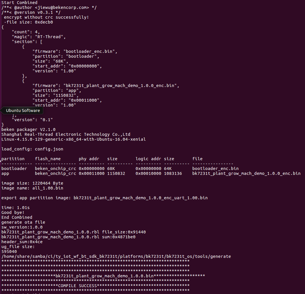
The following figures show a successful return.
After burning firmware to the module, we move to functional debugging. For more information about burning and authorization, see Burn and Authorize WB Series Modules.
-
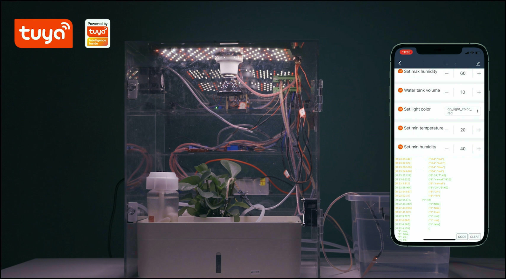
Step 5: Debug
Once the module is authorized, we connect the mobile phone to a Wi-Fi network, turn on Bluetooth, and pair the garden as per the instruction. Then, we can control the garden with the app. In this project, we use Tuya Smart app as the control terminal. There are different app options. For more information, see App Development.
The followings show debugging procedure:
Procedure 1: Scheduled and auto light filling
-
Switch on the garden and set Countdown.
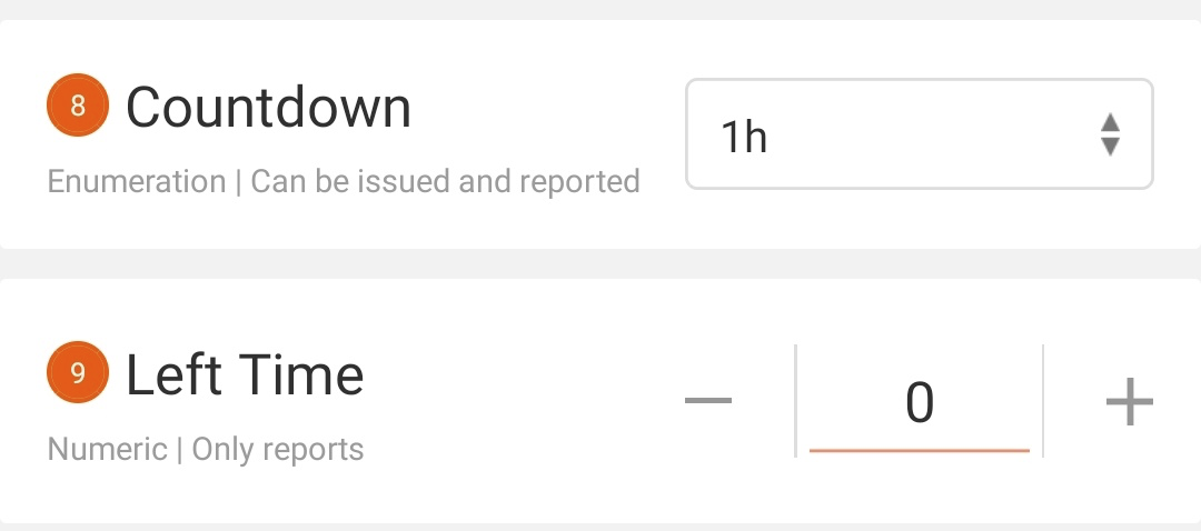
-
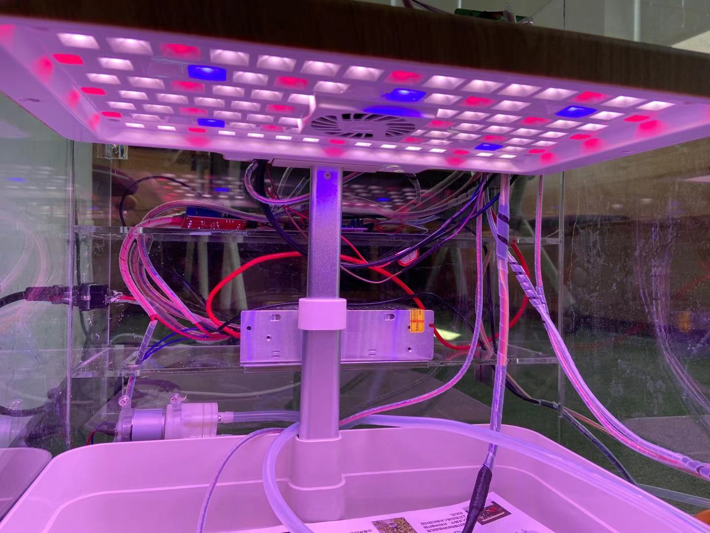
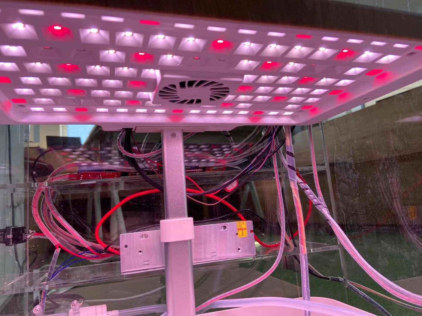
Set a light color and the grow light board changes color accordingly.
-
When Countdown is set to Cancel, the grow light board will be switched off.
-
When you enable auto light filling, the light brightness will keep increasing until the preset value is reached.
Procedure 2: Temperature and humidity control
-
You can view the current ambient temperature and humidity on the Tuya Smart app.

-
If you set a min humidity greater than current humidity, the mist maker will start. When the ambient humidity exceeds the min value, the mist maker will stop.

-
If you set a min temperature greater than current temperature, the infrared bulb will turn on. When the ambient temperature exceeds the min value, the infrared bulb will stop.
-
Test the max temperature and humidity the same way and see the cooling fan operate accordingly. This fan can dehumidify and cool down the air.
Procedure 3: Fill water tank
-
You can view remaining water percentage in water tank level.
-
Enable Pump on the Tuya Smart app to switch on water pump.
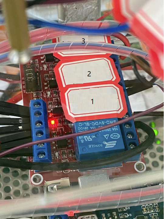
- 1: Relay module for ventilating
- 2: Relay module for spraying
- 3: Relay module for filling water tank
-
Put the water level sensor into a cup and add water until copper traces are fully submerged. You will find the water pump stops and Pump on the app restores.
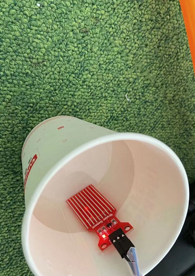
-
The water tank level becomes 100.

Procedure 4: Auto watering
-
When you switch on the garden, the water pump for watering will continuously operate.
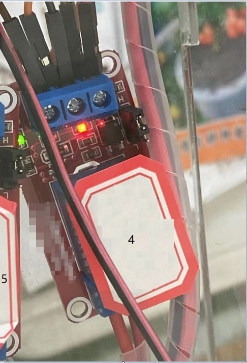
- 4: Relay module for watering
- 5: Relay module for heating
- Put the soil moisture sensor into water and simulate the condition where the soil moisture reaches a threshold. You will find the water pump stops.
-
Summary
Congratulations! You have successfully prototyped a smart indoor garden. Backed by the Tuya IoT Platform, you can quickly and easily build various smart prototypes from scratch.
Is this page helpful?
YesSuggestions


