Prototype a BLE Smart Socket (MCU control)
Overview
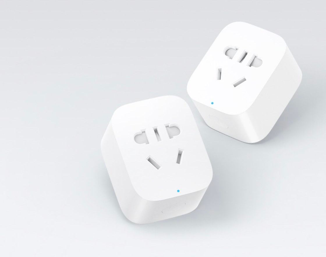
The smart socket is a common smart device that can be used to remotely control the connected electrical appliances and check their real-time status, thereby dramatically facilitating users’ lifestyles. You can quickly develop a smart socket on the Tuya IoT Platform. This topic describes how to prototype a smart socket with the Tuya Sandwich development board.
Solution overview
Different from the SoC solution, the MCU solution allows you to develop MCU code independently with more traits. The driver code of the switch and network module is written to the MCU.
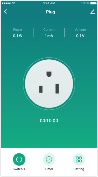
In the socket kit of the Tuya Sandwich development board, the MCU outputs high and low levels to control the socket on/off. It connects to the BLE communication board through a serial port. With the Tuya Smart app, you can pair the socket, view on/off status, and link the socket with other devices. In this demo, the MCU model is STM32G071RB, and the Arduino IDE is used for writing and compiling code.
Materials
Tuya Sandwich socket board
Count:1AC on/off control and energy monitoring. The board adopts the BPS BT01 power chip, Belling BL9037 metering chip, Belling BL1117-3.3 LDO chip, Hongfa relay, and other key components to implement the functions of metering and power cut.more
NUCLEO-G071RB
Count:1Official development board with STM32G071RB MCU. Control socket on/off and module communication. The NUCLEO-G071RB development board supports the Arduino interface.more
Tuya Sandwich BLE MCU communication board (BT3L)
Count:1Onboard Tuya BT3L module implements networking functionality. The module has been burned with general firmware, and the MCU is connected to the Tuya serial port protocol to enable smart one-stop service of Tuya module, app, cloud, and more.more
Steps
Step 1: Hardware connection
The temperature and humidity sensor kit of the Tuya Sandwich development board consists of the following:
- Socket board
- BLE MCU communication board
- ST’s official NUCLEO-G071RB development board (MCU control board)
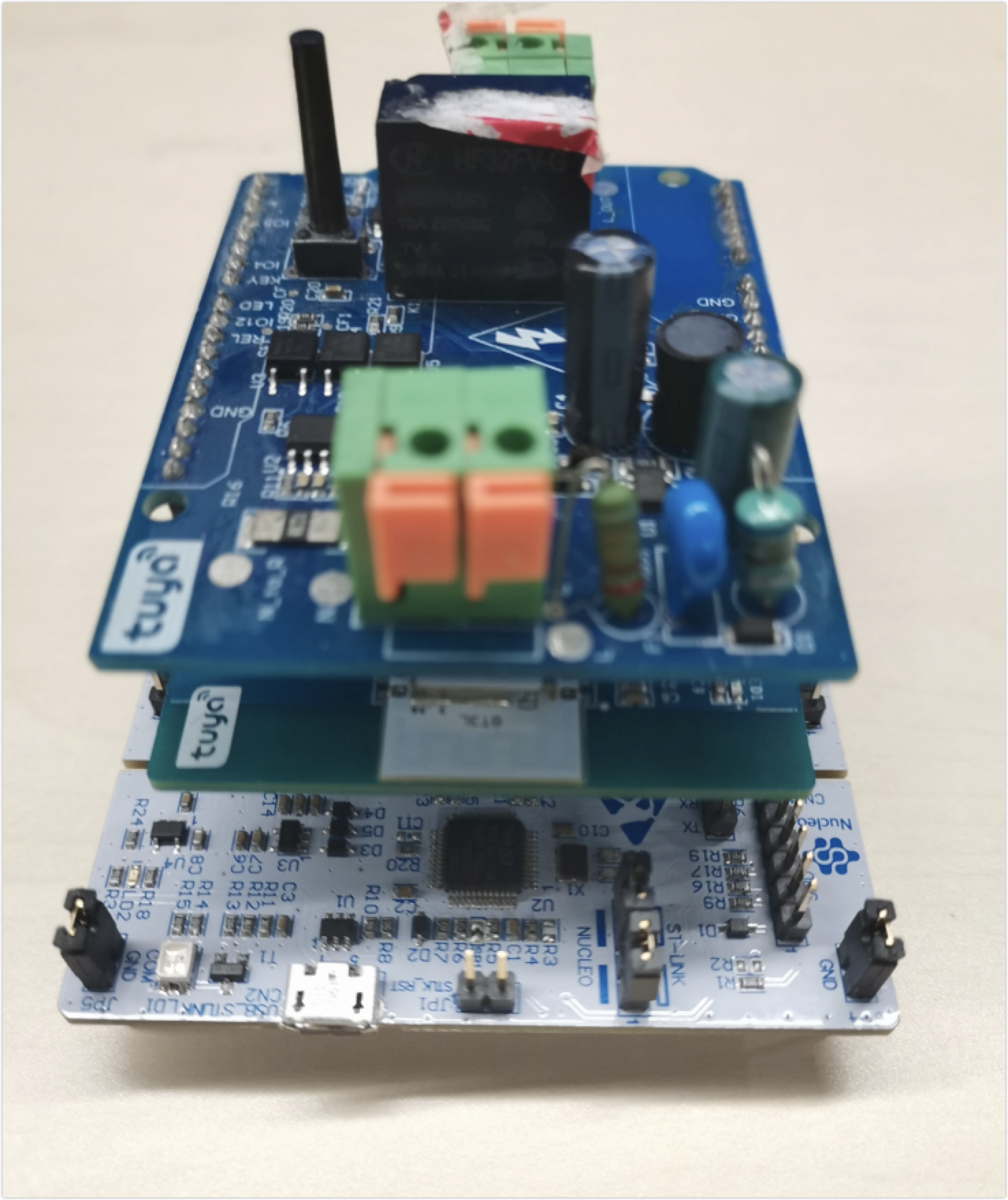
Assemble the control board, communication board, and function board of the sandwich development board kit, as it is shown below.
Step 2: Routine environment
The software development is based on the connection of MCU to socket and module protocol by Arduino. Make sure the communication between the MCU and the module works properly to pair through the app and transfer MCU data to the app.
See MCU Development Environment Building to complete environment building for Sandwich development board. You need to add an ST development board to the Arduino IDE and integrate STM32CubeProgrammer to enable the compiling and downloading function.
Step 3: Create a product and project
-
Log in to the Tuya IoT Platform.
-
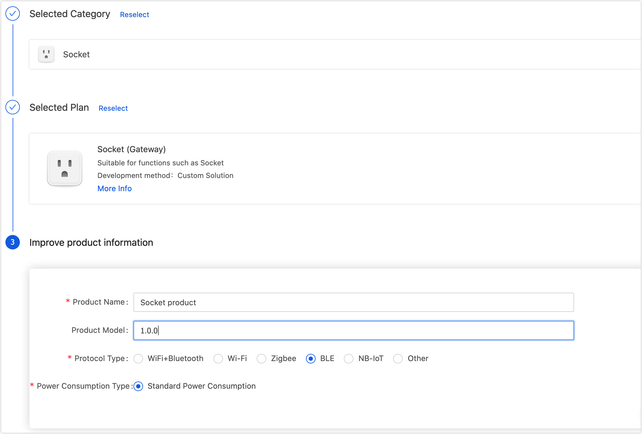
See Create Products to create a socket. The product attributes are as follows:
-
Development method: Custom solution
-
Protocol type: BLE
-
Power consumption type: Standard power consumption
-
-
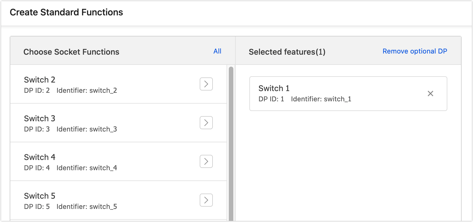
Select standard and custom functions for the product as per the prompts. For example, select switch function.
-
Select an ideal panel. For the first time debugging, you can also select a development debugging panel, which can be changed in the following steps.
-
Enter the Hardware Development stage. Select BT3L Bluetooth module and BLE common firmware.
-
Download the development materials at the bottom of the page.

-
Hardware debugging.
After downloading MCU development documents, you can use the Tuya Module Debugging Assistant in the documents to help debug the module communication board, verify whether the communication works properly, as well as get to know the Tuya serial port protocols for higher connection efficiency. If the communication board works properly, you can skip this step. If you have questions about protocol sending and receiving during debugging, you can also use this assistant to check the correct data transmission format. See Module Debugging Assistant for usage steps.
-
See MCU Quick Start to debug migration.
When the migration is completed with pairing, you can see the selected panel.
-
Step 4: Function board debugging
In this section, you can see the sample code of the application layer to debug the socket’s functions. The app sends on/off commands to the module. The MCU executes commands accordingly and sends the socket status to the module. You can see the socket status in the app.
#include "bluetooth.h"

#include <SoftwareSerial.h>

SoftwareSerial mySerial(0, 1); // RX, TX

#define _SS_MAX_RX_BUFF 300

#define relay 10

int time_cnt = 0, cnt = 0, init_flag = 0;


void setup()
{
// put your setup code here, to run once:

pinMode(relay, OUTPUT);   // Initialize relay I/O

digitalWrite(relay, LOW);

pinMode(PC13, INPUT);     // Initialize Bluetooth reset key

pinMode(8, OUTPUT);       // Initialize Bluetooth status indicator

mySerial.begin(9600);     // Initialize software serial port

mySerial.println("myserial init SUCCESS_ful!");

Serial.begin(115200);     //PA3 RX   PA2 TX

Serial.println("serial init SUCCESS_ful!");

bt_protocol_init();
}

void loop()
{
// put your main code here, to run repeatedly:
if (init_flag == 0)
  {
  time_cnt++;
  if (time_cnt % 6000 == 0)
    {
    time_cnt = 0;
    cnt ++;
    }
  bt_stat_led(&cnt);   // Process Bluetooth status
  }
bt_uart_service();
myserialEvent();      // Process serial port receiving
key_scan();           // Detect pairing reset key
}

void myserialEvent()
{
if (mySerial.available())
  {
  unsigned char ch = (unsigned char)mySerial.read();
  uart_receive_input(ch);
  }
}

void bt_stat_led(int *cnt)
{
#define bt_stat_led 8
switch (mcu_get_bt_work_state())
  {
  case 0x00:  // 0x00
  init_flag = 0;
    if (*cnt == 2)
      {
      *cnt = 0;
      }
    if (*cnt % 2 == 0)  // LED flicker quickly
      {
      digitalWrite(bt_stat_led, LOW);
      }
    else
      {
      digitalWrite(bt_stat_led, HIGH);
      }
    break;

  case 0x01:  // 0x01
  init_flag = 0;
    if (*cnt >= 30)
      {
      *cnt = 0;
      }
    if (*cnt  == 0)    // LED flickers slowly
      {
      digitalWrite(bt_stat_led, LOW);
      }
    else if (*cnt == 15)
      {
      digitalWrite(bt_stat_led, HIGH);
      }
    break;

  case 0x02:  // 0x02
  digitalWrite(bt_stat_led, HIGH); // LED is off
    break;

  case 0x03:  // 0x03
    break;

  case 0x04:  // 0x04
    if ( 0 == init_flag )
      {
      digitalWrite(bt_stat_led, LOW); //  LED is always on

      init_flag = 1;
      // The light is controllable with Bluetooth connected

      *cnt = 0;

      }
    break;


  default:
  digitalWrite(bt_stat_led, HIGH);
  break;
  }
}
Summary
Based on the Tuya IoT Platform, you can quickly prototype a smart socket with the Tuya Sandwich development board and Arduino IDE programming.
Is this page helpful?
YesSuggestions


