Tuya Sandwich Socket Board
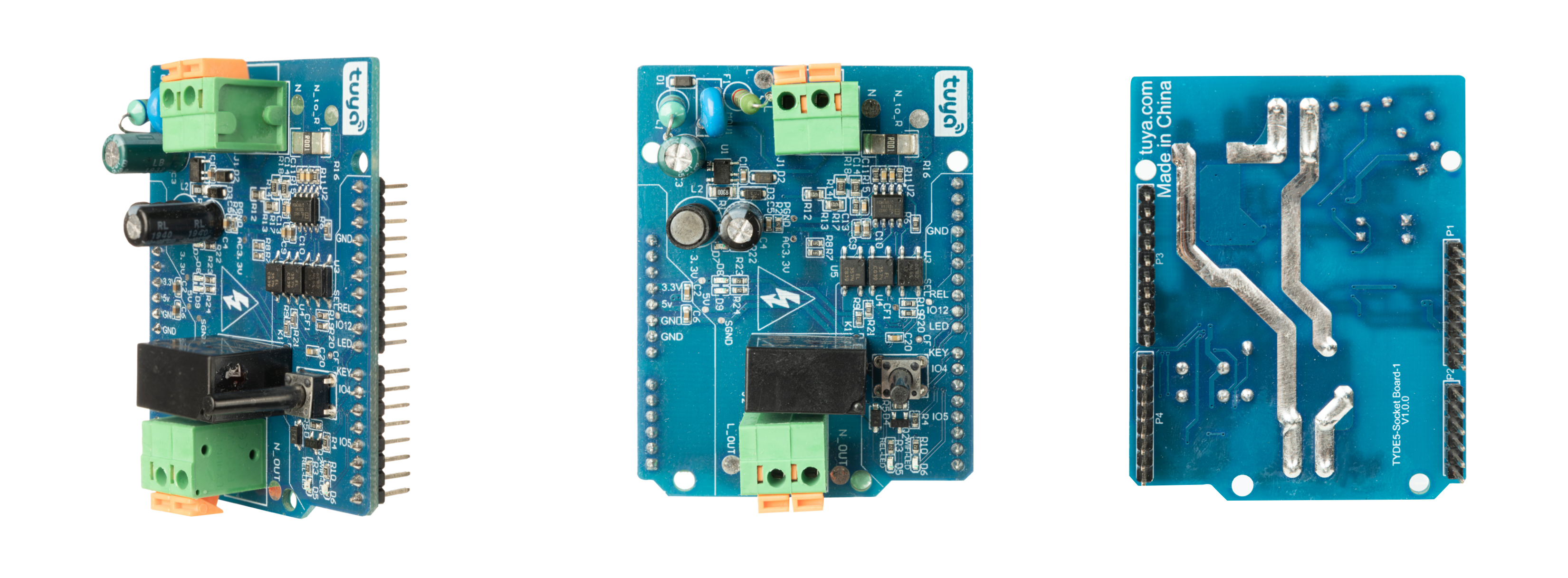
The Tuya Sandwich socket function board is a multi-functional breaker that supports metering and power cut, and it uses an AC 220V power input. The board adopts the Jingfeng BT01 power chip, Belling BL9037 metering chip, Belling BL1117-3.3 LDO chip, Hongfa relay, and other key components to achieve the functions of metering and power cut.
Function and connection control method
-
The board uses opto-isolator to isolate strong and weak electrical signals to ensure the safety of operators working in the debugging and testing environment.
-
The Tuya Sandwich socket function board must be used together with the Tuya Sandwich Wi-Fi SoC master control board (E3S). By configuring the I/O pin of E3S SoC, the function board can output control signals to the relay, switch signals to the metering chip, and collect the data of voltage, current, and power.
Introduction to key components
Tuya Sandwich socket function board contains an ACDC chip for power supply of the metering chip, a Belling BL9037 metering chip, a Belling BL1117-3.3 LDO chip, and a Hongfa relay. It is shown as follows.
| Components | Description |
|---|---|
| U1 (BT01) | Ultra-low standby power non-isolated AD to DC step-down constant voltage chip |
| U2 (BL0937) | Wide-range single-phase multi-function power metering chip with 3.3V power supply |
| U3 (BL1117) | Linear stable voltage chip |
| K1 (HF32FV-G/5-HSTF (590)) | One group is normally open. It uses 5V power to drive an electromagnetic relay. |
Introduction to I/O ports
The socket function board has plenty of peripheral ports. The pins used in the board are shown as below:
| I/O | Description |
|---|---|
3.3V |
3.3V power supply pin, which is used to supply power to some circuits of the ELV circuit part. |
| 5V | 5V power supply pin, which is used to supply power to the relay coil and peripheral circuit. |
| GND | Power ground of 5V and 3.3V power. |
| Relay | I/O input signal, which is used to control the relay. When the logic level is high, the relay contact is on. |
| Key | Key S1 signal. The default voltage is 3.3V. When S1 is pressed, the output voltage is 0V. |
| Wifi_led | Wi-Fi LED indicator light control signal. When the logic level is low, the light is on. |
| I/O4 | Battery level signal (CF) of the battery chip, which is a pulse signal. |
| I/O5 | Voltage and current signal (CF) of the battery chip, which is a pulse signal. |
| I/O12 | The voltage and current switching control pin of the battery chip. The CF1 pin of the battery chip outputs voltage signal when the logic level is high and outputs the current signal when low. |
Technical requirements
- Connector J1: Electrical 220V AC input.
- Connector J2: Relay control output, which is connected to load.
- ELV DC supply voltage: 3.3V and 5V, which is isolated from the electrical 220V AC power supply.
- The average current of 3.3V power supply: Less than 200 mA. It is mainly used for the power supply of opto-isolator and indicator light.
- The average current of 5V power supply: Less than 200 mA. It is mainly used for driving the relay coil.
- The socket function board contains both electrical and ELV circuits. Do not touch the board when the power is on.
Schematic diagram and PCB
-
Schematic diagram of the Tuya Sandwich Socket Board:
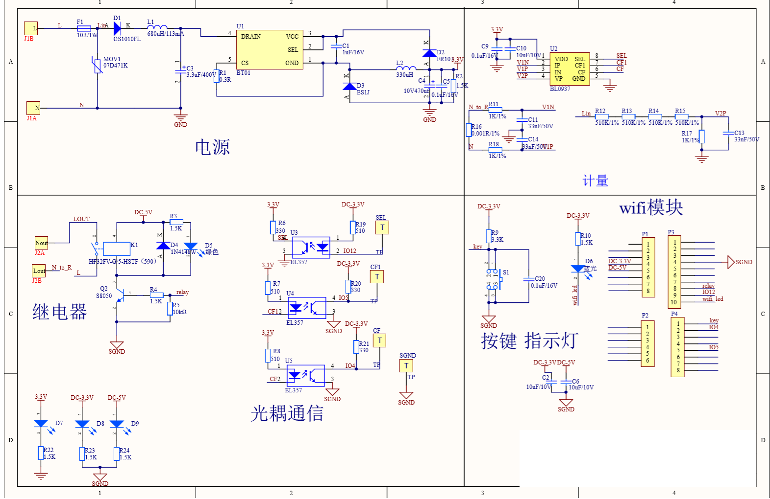
-
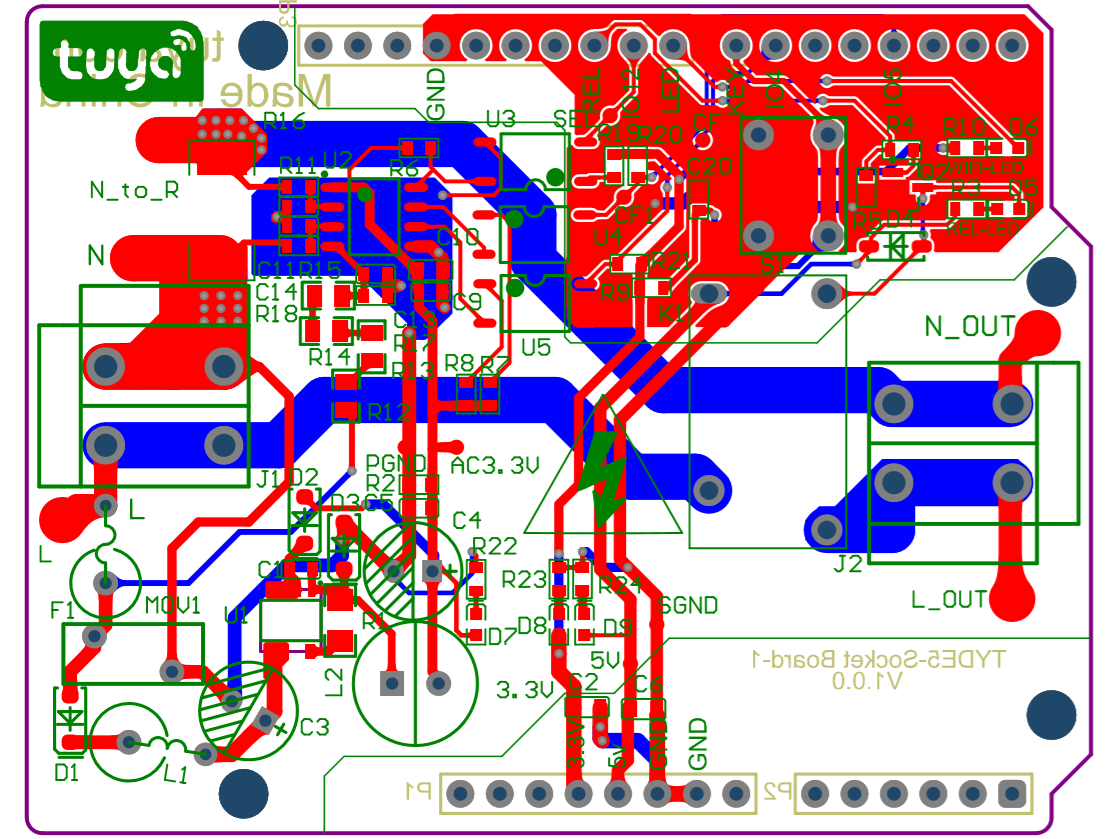
PCB of the Tuya Sandwich Socket Board:
Things to note
- The socket function board needs to be used with a control board and power supply board.
- The socket function board contains both electrical and ELV circuits. Do not touch the board when the power is on.
- To operate normally, the metering chip needs strong current input.
Reference
Is this page helpful?
YesFeedbackIs this page helpful?
YesFeedback


