Tuya Sandwich Power Socket Board
Last Updated on : 2024-06-19 08:19:19Copy for LLMView as MarkdownDownload PDF
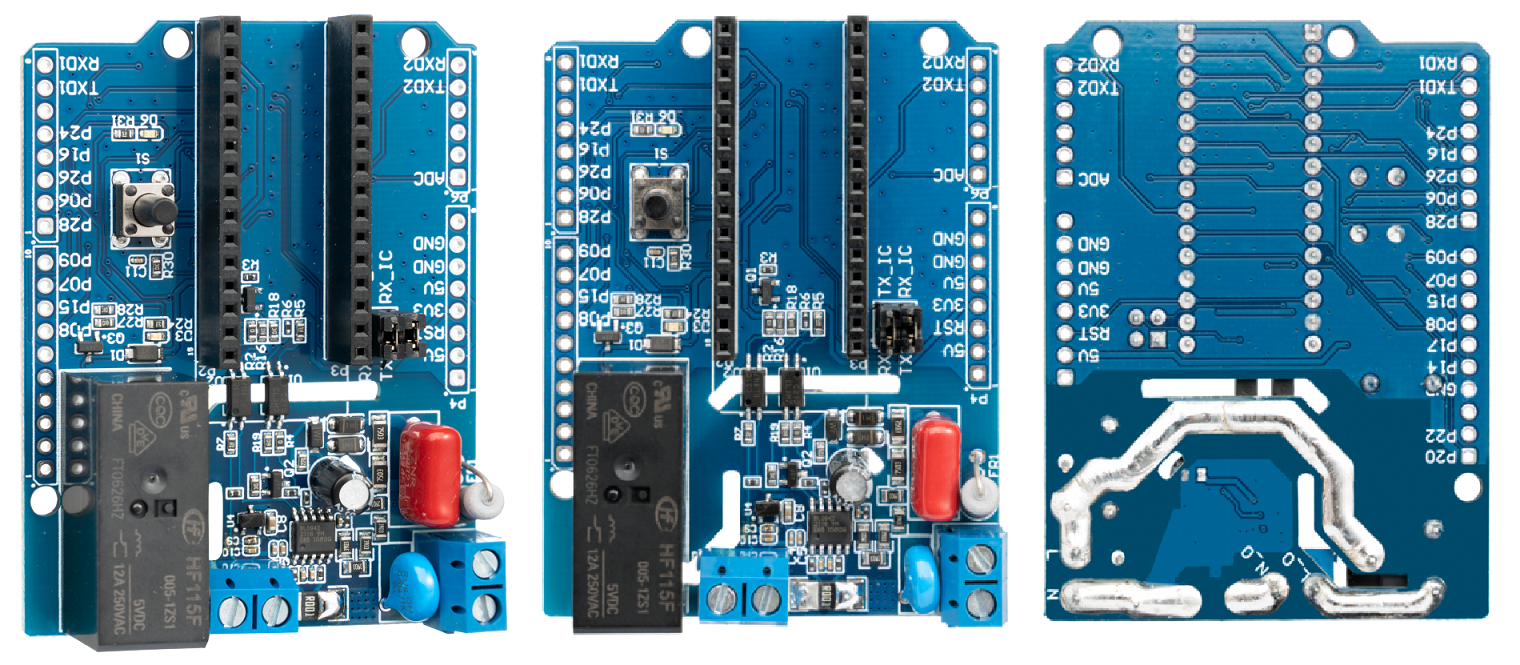
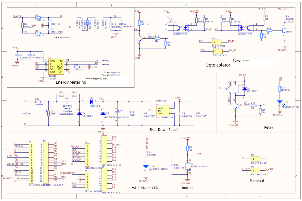
Tuya Sandwich power socket board features energy metering, output power-down, and 220V AC input. This board consists of a resistor-capacitor step-down circuit, Belling’s BL0942 energy metering IC, Everlight’s EL3H7CTA-G optocoupler, HONGFA’s relay, and Natlinear’s LN1173B332MR.
Function and connection
- This board uses an optocoupler to isolate your circuit from high voltage systems, providing a safe environment for personnel to work in.
- This board is used in tandem with the Tuya Sandwich microcontroller board. It transmits control signals to the relay by setting the I/O pins on the microcontroller board, and reads data such as voltage and current measured by the energy metering IC through the UART1.
Components
This board consists of a Belling’s BL0942 energy metering IC, resistor-capacitor step-down circuit that supplies power to the energy metering IC, Everlight’s EL3H7CTA-G optocoupler, HONGFA’s relay, and Natlinear’s LN1173B332MR.
| Component | Description |
|---|---|
| U1 and U2 (EL3H7CTA-G) | The optocoupler used to isolate the circuit from high voltage systems, preventing electric shock. |
| U3 (BL0942) | The single-phase multifunctional energy metering IC that operates from a 3.3 V input voltage and has a calibration-free clock. |
| C6 (220 nF CBB) | The capacitive reactance limits the current flowing through the main circuit. |
| U4 (LN1173B332MR) | The linear regulator. |
| K1 (HF115F) | The 5V power relay. |
Pin functions
The board offers a variety of peripheral interfaces. The following table lists the pin functions.
| I/O | Description |
|---|---|
| 3V3 | 3.3V input pin, used to supply power to the low-voltage circuit. |
| 5V | 5V input pin, used to supply power to the relay coil and peripheral circuit. |
| GND | 5V and 3.3V power ground. |
| P24 (K1 Relay) | I/O input signal, used to control the relay. When the input control signal is high level, the relay is on. |
| P26 (Button S1) | The button S1 signal, defaulting to 3.3V. When the button is pressed, 0V is output. |
| P28 (Wi-Fi LED) | The control signal for Wi-Fi status LED. The LED comes on at a high level. |
| TX_IC | BL0942’s TX pin that is converted through the optocoupler is connected to RX1 on the microcontroller board with an H1 2.54 mm jumper cap. |
| RX_IC | BL0942’s RX pin that is converted through the optocoupler is connected to TX1 on the microcontroller board with an H1 2.54 mm jumper cap. |
Power requirements
- Terminal U5: connected to 220V AC input.
- Terminal U6: connected to a load. The relay controls the output voltage.
- AC power supply for low-voltage circuit: 3.3V and 5V, which is isolated from the 220V AC input but not isolated from the power supply to BL0942.
- Average current for 3.3V power supply: less than 200 mA, used to supply power to the optocoupler and button.
- Average current for 5V power supply: less than 200 mA, used to drive the relay coil.
- Tuya Sandwich power socket board consists of the mains-power circuit and low-voltage circuit. When power is connected, do not touch the board to prevent a possible shock.
Schematic diagram and PCB
The schematic diagram of the board:
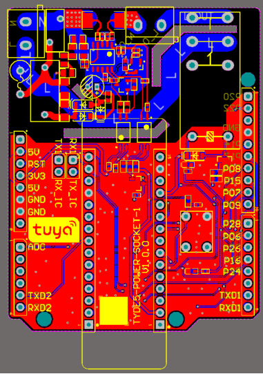
The PCB board:
Things to note
- The power socket board must be used in tandem with the microcontroller board and power supply board.
- It consists of the mains-power circuit and low-voltage circuit. When power is connected, do not touch the board to prevent a possible shock.
- Make sure to supply high voltage to the energy metering IC for proper operation.
- AC power supply below 176V can cause insufficient voltage at the energy metering IC. If low voltage is required, you can adjust the resistor-capacitor step-down circuit.
Reference
Is this page helpful?
YesFeedbackIs this page helpful?
YesFeedbackMarketing Cooperation
Business Cooperation
Customer Service
Media Inquiry


