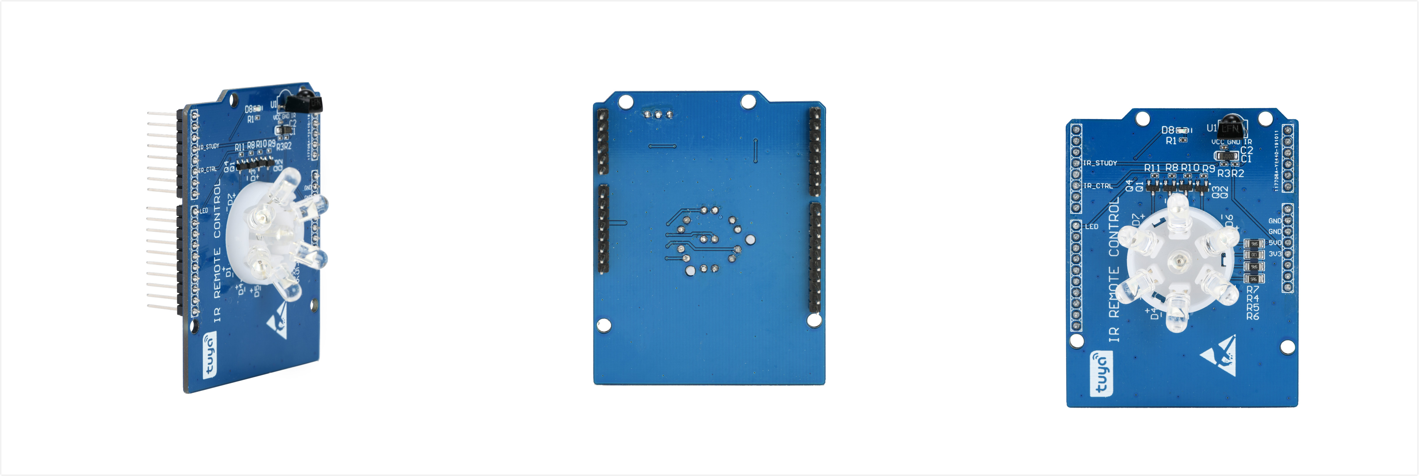
Tuya Sandwich Infrared Remote Control Board
Last Updated on : 2024-06-24 03:06:04download
The Tuya Sandwich infrared remote control function board is a wireless transmitting and receiving device. It can learn, decode, and save the 37.9 kHz central frequency infrared signal, and control the infrared devices through the open or closed status of the IR LED.

Product features
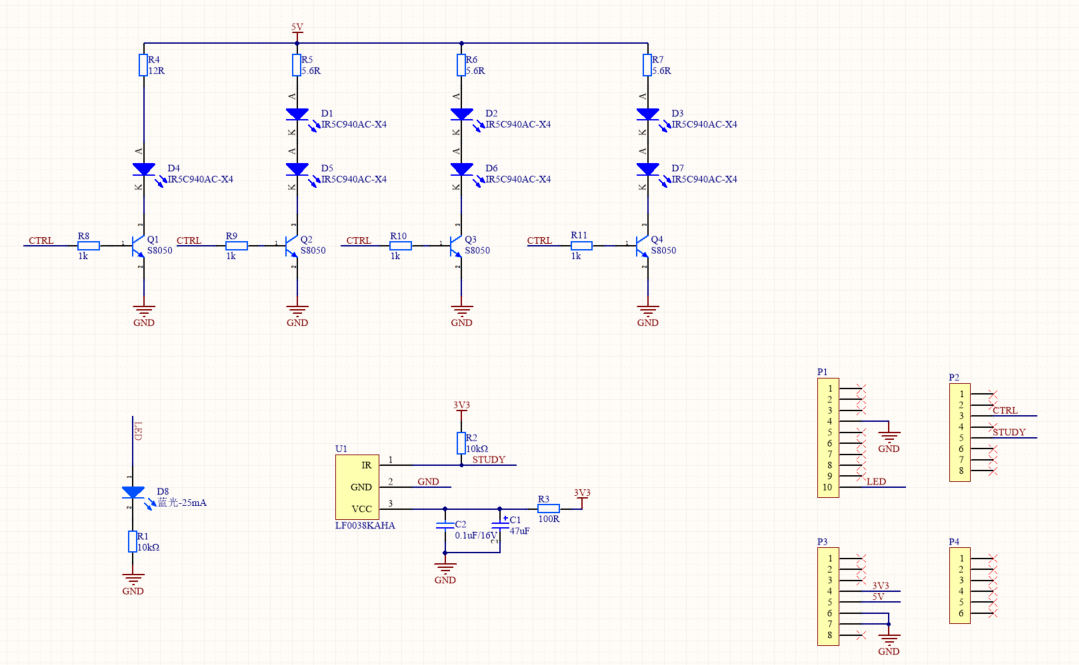
- The infrared remote control board requires 5V DC and 3.3V DC power input. The 5V DC supplies power to the IR LED which adopts a serial-parallel combination circuit and is controlled by the logic level generated through the triode base.
- There are seven IR LEDs in total. One LED in the center is vertical to the PCB, and the other six LEDs are placed on the circle centered by the central LED with a 60° interval to ensure 360° coverage of IR signals. The IR LED has the advantages of strong emitting power and a uniform light-receiving angle.
- The 3.3V DC power input is used for the integrated infrared receiver. Because the receiver is easily interfered by external signals, several filter capacitors are connected in parallel between VCC and GND. An RC filter that consists of a resistor and a capacitor is connected in series between VCC and 3.3V power input, and a pull-up resistor is placed on the signal emitting unit to ensure the stability of the receiver. The integrated receiver has the advantages of low power consumption, wide receiving angle, and strong anti-interference capability.
- The LED indicator light is used to indicate the device’s current status.
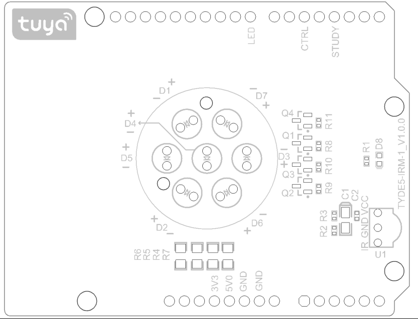
- You can view the peripheral ports through the silk screen on the board, and directly access the control port to use it.
Introduction to key components
| Components | Description |
|---|---|
| U1 (LF0038KAHA) | Integrated IR receiver that has a strong anti-interference capability and 37.9 KHz central frequency. |
| D1-D7 (IR5C940AC-X4) | 5 mm in-line IR LED. Its central wavelength is 940 nm. |
Introduction to I/O ports
See the following table for the pins that are used in the Tuya Sandwich infrared remote control function board:
| I/O | Description |
|---|---|
| 5V | 5V power supply pin |
| 3V3 | 3.3V power supply pin |
| GND | Power ground |
| LED | Indicator light control pin which is active high |
| IR_CTRL | IR LED control pin which is active high |
| IR_STUDY | IR receiver diode output signal |
Technical requirements
- Power supply voltage: 3.3V and 5V
- The average current of 3.3V power supply: Less than 1 mA.
- The maximum output current of 5V power supply: 500 mA.
Schematic diagram and PCB
-
Schematic diagram of Tuya Sandwich infrared remote control function board:

-
PCB of Tuya Sandwich infrared remote control function board:

Things to note
- The development board needs to be used with the control board and the power supply board.
- The development board uses both 5V and 3.3V power supplies which share the GND port.
- The development board supports IR codes of all frequencies, but can only learn the code with 38 kHz central frequency.
- Do not insert the I/O pin into the power port to prevent a chip breakdown.
- The port control signal on the development board corresponds to I/O ports on the module.
Reference
Is this page helpful?
YesFeedbackIs this page helpful?
YesFeedback


