Prototype NB-IoT Smart Contact Sensors (MCU Control)

Overview
The smart contact sensor plays an important role in smart security with more and more application scenes. Unsure of whether the doors and windows are closed after leaving home? You might as well check it with your phone. This demo describes how to prototype an NB-IoT module based smart contact sensor with Tuya Sandwich development board, implementing two basic functions of the door sensor and battery level.
Different from the SoC solution, the MCU solution allows you to develop MCU code independently with more traits. The driver code of the sensor and network module is written to the MCU. In the contact sensor kit of the Tuya Sandwich development board, the reed switch of the sensor board outputs high and low levels to the MCU control board corresponding to the open and closed status. The MCU connects to the NB-IoT communication board through a serial port, allowing you to pair the contact sensor with the Tuya Smart app. You can view the contact sensor status on the phone and link the sensor with other devices. In this demo:
- The MCU model is STM32G071RB
- The demo adopts Keil (MDK-ARM) as the development environment and uses STM32CubeMX to generate initialization code.
Materials
Tuya Sandwich NB-IoT communication board (NM1)
Count:1Provide pairing capability in collaboration with the MCU.more
Tuya Sandwich function board of contact sensor
Count:1Determine the open and closed status by the logic levels generated by moving the magnet close to or away from the reed switch.more
NUCLEO-G71RB
Count:1
Steps
Step 1: Hardware connection
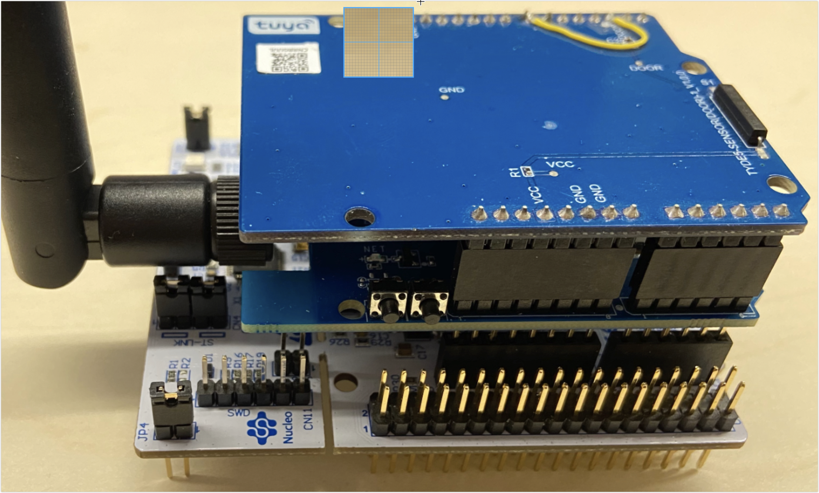
The contact sensor kit of the Tuya Sandwich development board consists of the following:
-
Function board of the contact sensor with 2-gang on-board reed switch. One gang is low-level trigger and the other is high-level trigger. You can select it as needed.
-
NB-IoT MCU communication board with Tuya’s on-board NM1 module implements networking functionality. The module has been programmed with general firmware, and the MCU is connected to the Tuya serial port protocol to enable smart one-stop services of the Tuya module, app, and cloud.
-
ST’s official NUCLEO-G071RB development board (MCU control board) implements data transmission and module communication control.
Assemble the control board, communication board, and function board of the Sandwich development board kit, as is shown below.
-
Step 2: Routine environment
STM32CubeMX is used to configure MCU initialization. Implement connection between the MCU and the sensor and module in Keil5. Make sure the communication between the MCU and the module works properly to pair through the app and transfer MCU data to the app.
Step 3: Create a project and product
You can quickly create a contact sensor on the Tuya IoT platform by the following steps.-
Log in to the Tuya IoT Platform.
-
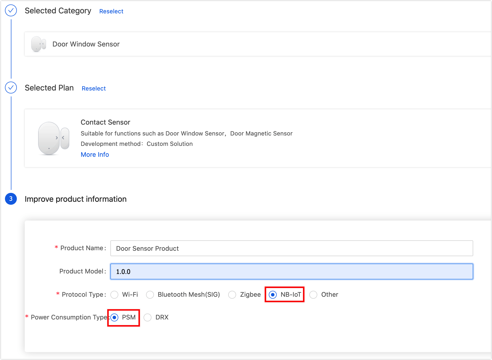
Refer to Create Products to create a contact sensor. The product attributes are as follows:
- Development method: Custom solution
- Protocol type: NB-IoT
- Power consumption type: PSM
-
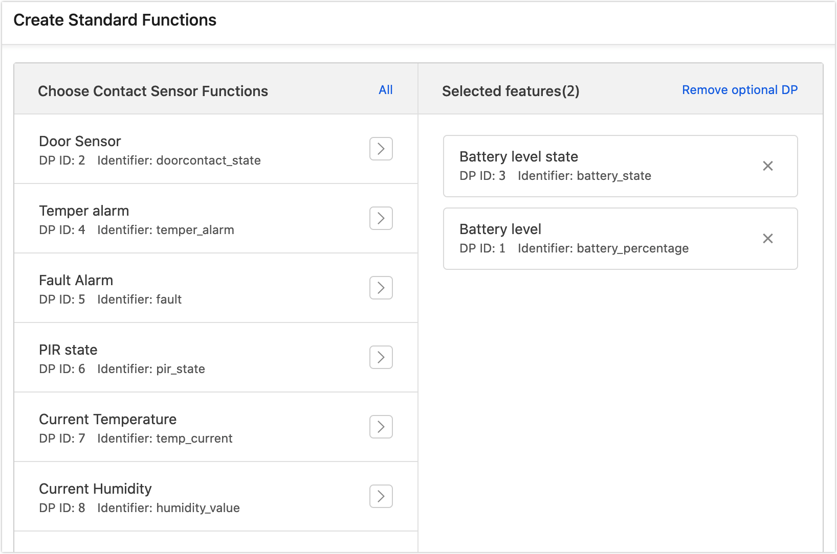
Select standard and custom functions for the product as per the prompts. Select Door sensor and Battery level. This demo routine supports only the two basic functions. You can implement other functions by yourself.
-
Select an ideal panel. For the first time debugging, you can also select a development debugging panel, which can be changed in the following steps.
-
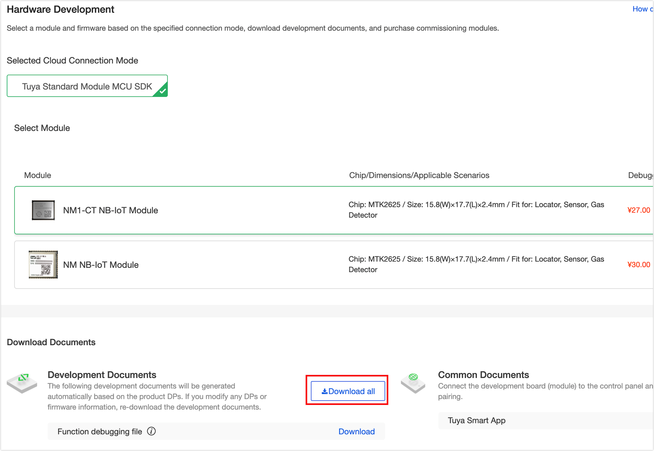
After selecting the panel, enter the Hardware Development stage and download development documents at the bottom of the page.
-
Hardware debugging.
After downloading MCU development documents, you can use the MCU simulation mode in the Tuya Module Debugging Assistant to debug the module communication board, verify whether the communication works properly, and get to know the Tuya serial port protocols for higher connection efficiency. If the communication board works properly, you can skip this step. If you have questions about protocol sending and receiving during debugging, you can also use this assistant to check the correct data transmission format. See Module Debugging Assistant for usage steps.
-
Step 4: Migrate the MCU SDK
After generating the initialization code with STM32CubeMX, it is ready to migrating MCU_SDK. This section briefly describes the migrating procedure and function implementation. Import the documents in
mcu_sdkinto the project, then compile and modify as the error prompts. For more information about the migration debugging demo, see MCU SDK Migration.-
Process the
uart_transmit_output()function as per the prompts in the#error, and comment it out afterward.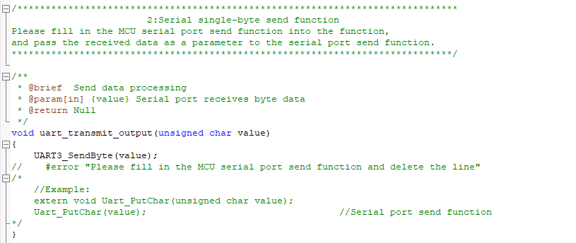
-
Complete the
uart_transmit_input()function as per the prompts in the#error, and comment it out afterward.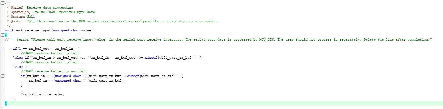
-
Process the
nbiot_uart_service()function as per the prompts in the#error, and comment it out afterward.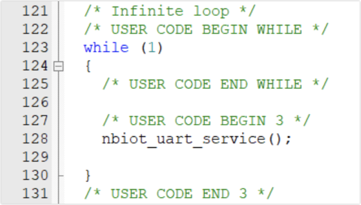
-
Process the nbiot_protocol_init()function as per the prompts in the#error, and comment it out afterward.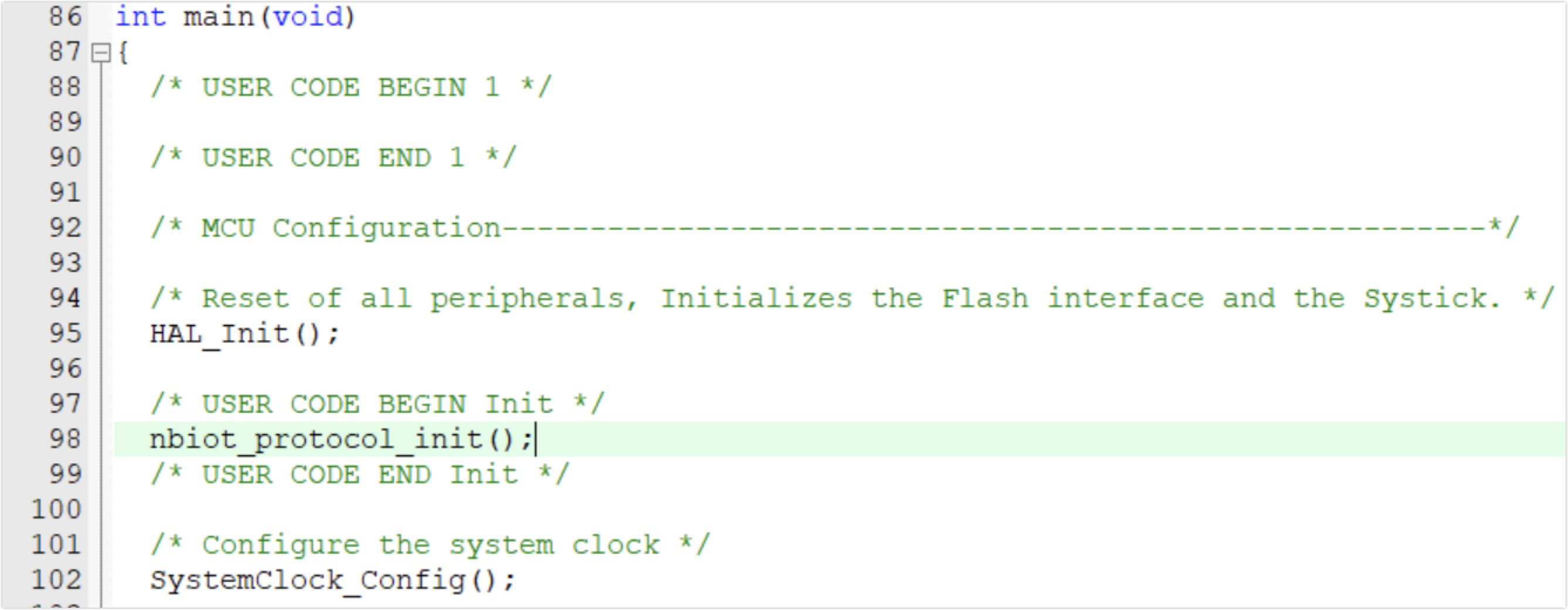
Do not call the
all_data_update()function as it reports all the DP information in the system automatically.-
Step 5: Write embedded program
-
Create a
user_func.hfile, and define a struct for recording the status of the contact sensor.// Sensor report flag typedef enum { STATE_IDLE = 0, STATE_DOOR_NEED_UP = 1 } sensor_state_t; // Open and closed status typedef enum { STATE_CLOSE = 0, STATE_OPEN = 1 } door_state_t; typedef struct { door_state_t door_state; sensor_state_t sensor_state; unsigned char door_up_lock; // Status reporting lock unsigned char remaining_power; // Remaining battery level in percentage } device_status_t; -
Implement some customized functions in the created
user_func.c, and meanwhile add header file#include "user_func.h"tonbiot.h file. -
Add header file
#include "nbiot.h"to filemain.c.
After the MCU is powered on and before entering thewhile(1){} loop, in addition to the regular configuration of the I/O port, serial port, and ADC, you need to perform:nbiot_protocol_init(); // Enable low power mode clock __HAL_RCC_PWR_CLK_ENABLE(); // Initialize wake-up pin level of the NB-IoT module HAL_GPIO_WritePin(GPIOA,GPIO_PIN_10,GPIO_PIN_SET);In the
while(1){}loop:while (1) { nbiot_uart_service(); power_detect_poll(); user_sensor_up_poll(); }-
nbiot_uart_service()is the function provided by the SDK for processing serial port data that parses and processes the data returned from the NB-IoT module. -
power_detect_poll()is the battery level detecting function that figures out and saves the approximate remaining battery level through ADC sampling and converting. It is self-implemented. -
user_sensor_up_poll()is a function for reporting executed tasks by the sensor. Based on the device status and other factors, it determines whether to report data and whether to make the MCU enter STOP low power mode. It is self-implemented.
 void user_sensor_up_poll(void)
{
// When the module is bound and connected, and the door status reporting lock is enabled. After receiving the successful return code by the module, the door status reporting lock will be enabled.
if ((NB_STATE_DEVICE_BINDED == mcu_get_nbiot_work_state()) && (device_status_s.door_up_lock))
   {
   // Interpret that there is an unprocessed door status reporting task, and start reporting data to the NB-IoT module.
   if (STATE_DOOR_NEED_UP == device_status_s.sensor_state)
      {
      device_status_s.sensor_state = STATE_IDLE;
      mcu_dp_bool_update(DPID_DOORCONTACT_STATE, device_status_s.door_state);
      device_status_s.door_up_lock = 0;
      }
   else
      {
      // Determine whether the remaining battery level is below the power reporting threshold,  send power reporting data, and lower the threshold.
      if (device_status_s.remaining_power <= power_threshold)
         {
         mcu_dp_value_update(DPID_BATTERY_PERCENTAGE, device_status_s.remaining_power);
         if(power_threshold >= 25)
            {
            power_threshold -= 25;
            }
         }
      // Enable the PSM sleep lock of the NB-IoT module
      mcu_set_nbiot_sleeplock(0);
      // The MCU enters low power mode
      enter_lowpower_mode();
      }

   }
}
Implement two functions to enter and exit low power mode:
void enter_lowpower_mode()
{
HAL_GPIO_WritePin(GPIOA,GPIO_PIN_10,GPIO_PIN_SET);
lowpower_gpio_init();
HAL_ADC_Stop(&hadc1);
HAL_ADC_DeInit(&hadc1);
HAL_UART_DeInit(&huart3);
// HAL_TIM_Base_DeInit(&htim3);

// Turn off the clock
__HAL_RCC_DMA1_CLK_DISABLE();
__HAL_RCC_GPIOB_CLK_DISABLE();
__HAL_RCC_GPIOC_CLK_DISABLE();
__HAL_RCC_GPIOC_CLK_DISABLE();
__HAL_RCC_GPIOD_CLK_DISABLE();
__HAL_RCC_GPIOF_CLK_DISABLE();
HAL_SuspendTick();

// Enter STOP mode
HAL_PWR_EnterSTOPMode(PWR_MAINREGULATOR_ON,PWR_STOPENTRY_WFI);
}

void leave_lowpower_mode()
{
SystemClock_Config();
MX_GPIO_Init();

// MX_TIM3_Init();
MX_USART3_UART_Init();
__HAL_UART_ENABLE_IT(&huart3, UART_IT_RXNE);
MX_ADC1_Init();
HAL_ADC_Start(&hadc1);

// Pull down the pin to wake up NB-IoT module
HAL_GPIO_WritePin(GPIOA,GPIO_PIN_10,GPIO_PIN_RESET);

// The sensor needs to report the door status
device_status_s.sensor_state = STATE_DOOR_NEED_UP;
}
The STOP low power mode of the MCU is wakened up by the interrupt. Hence it is required to call
nbiot_uart_service()in the interrupt callback function and record the door status:void HAL_GPIO_EXTI_Falling_Callback(uint16_t GPIO_Pin) { leave_lowpower_mode(); device_status_s.door_state = STATE_OPEN; } void HAL_GPIO_EXTI_Rising_Callback(uint16_t GPIO_Pin) { leave_lowpower_mode(); device_status_s.door_state = STATE_CLOSE; }The NB-IoT module needs to reconnect to the Tuya Cloud after waking up from the PSM mode. The first door status reporting will fail after waking up. Therefore it is required to resend the status report when the module is connected successfully and the working status code is returned, namely to implement by adding codes to the working status processing case of the
data_handlefunction in thesystem.c.// Working status case NBIOT_STATE_CMD: nbiot_work_state = nbiot_uart_rx_buf[offset + DATA_START]; nbiot_uart_write_frame(NBIOT_STATE_CMD,0); if (STATE_DOOR_NEED_UP == mcu_get_nbiot_work_state()) { mcu_dp_bool_update(DPID_DOORCONTACT_STATE, device_status_s.door_state); device_status_s.sensor_state = STATE_IDLE; } break;Add codes to the working status processing case of the
data_handlefunction in thesystem.c.case STATE_UPLOAD_CMD: // Evaluate the result value. Enable the door status reporting lock and prepare for the next report after the information returned by the module is received. device_status_s.door_up_lock=1; break; -
-
Step 6: (Optional) Scene linkage
After the product function is debugged, the app can receive the contact sensor data. The most common application of the smart sensor is to collect sensor data and create linkage to other products. If you have other ‘Powered by Tuya’ devices or development boards, you can implement the configuration of the scene linkage with the app. For specific procedures, see Automate the Smart Devices.
Summary
Based on the Tuya IoT Platform, you can quickly prototype a smart contact sensor with Sandwich development board and STM32CubeMX in the Keil development environment.
Is this page helpful?
YesSuggestions


