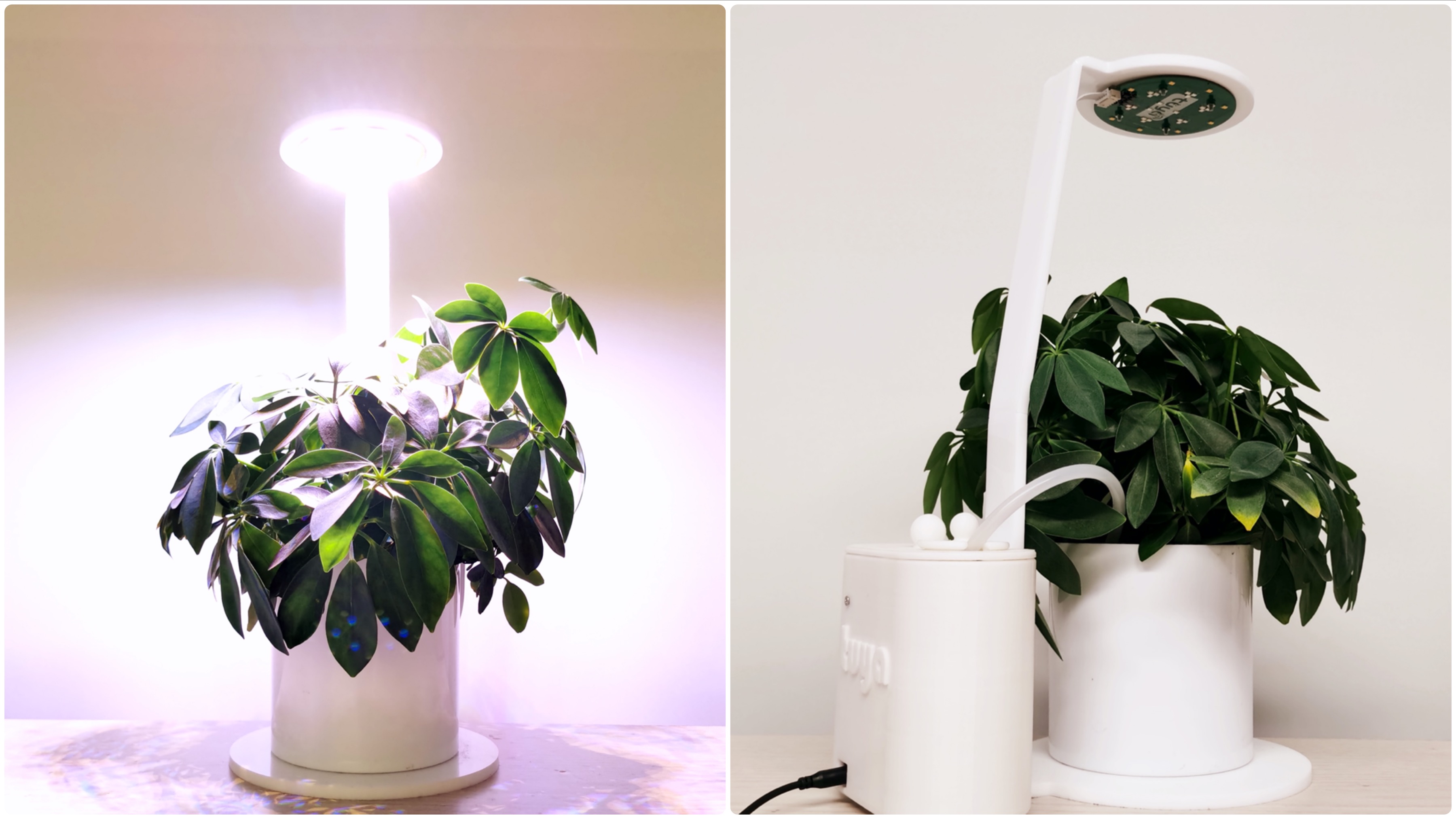
Smart Indoor Garden Lite
Overview
In this project, we will show you how to build a simpler version of an indoor garden system, which can do the hard work for you and take good care of your plants. If you are interested in developing a fully-functional indoor garden, find our previous project Fully-Functional Smart Indoor Garden.
What to expect
- Remotely controlled and monitored with an app
- Monitor soil moisture
- Automatic grow light filling
- Self-watering
- Custom grow light colors
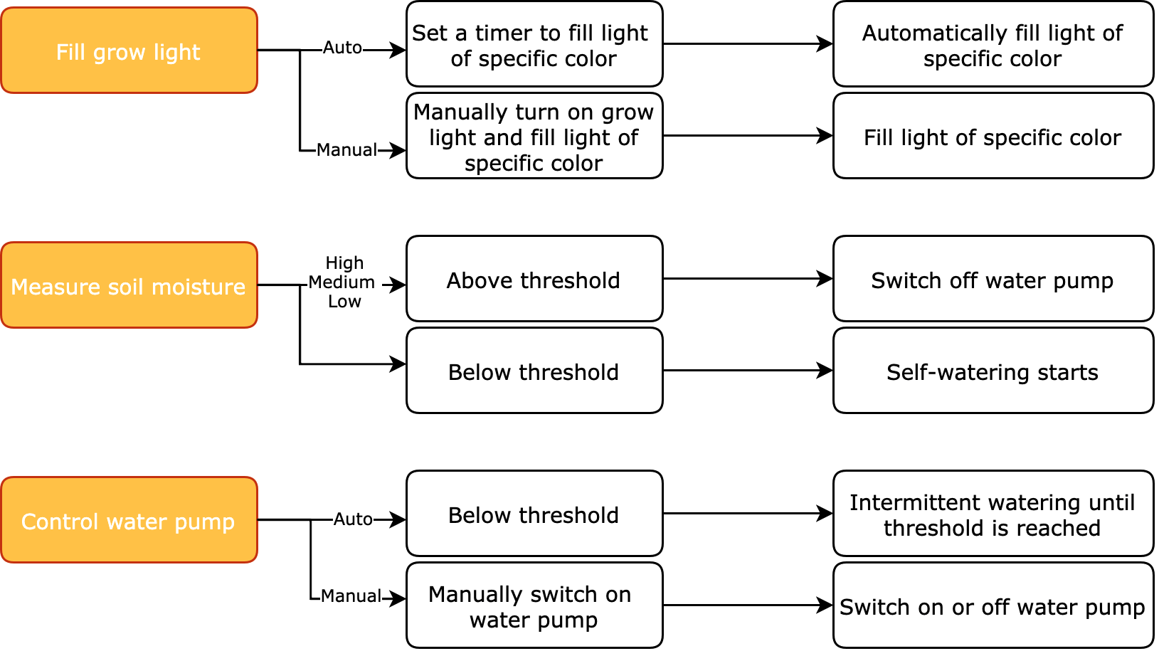
How it works?
Materials
Tuya Sandwich Wi-Fi SoC master control board (WB3S)
Count:1A development board helps you easily prototype IoT hardware.more
Functional board
Count:1Provide 12V DC power supply, control the water pump and PWM grow light board, and read analog values from the soil moisture sensor.
Warm white and multi-color (RGBW) PWM grow light board
Count:1Dim the RGBW grow light with an app to provide the spectrum needed for plant growth.
Vertical micro submersible water pump
Count:1The pump delivers water from your container to plants.
Capacitive soil moisture sensor module
Count:1Measure soil moisture.
XH 2.54 mm 2-pin male connector wire
Count:1Length: 80 mm
XH 2.54 mm 3-pin male to male reversed connector wire
Count:1Length: 150 mm
XH 2.54 mm 5-pin male to male reversed connector wire
Count:1Length: 400 mm
C-shape acrylic light fixture
Count:1Fixture
Water tank structure
Count:13D printing is recommended.
M3 × 16 mm flat-head machine screw
Count:8Standard specification
M3 hexagon nut
Count:4Standard specification
Silicone tubing hose
Count:1Connected to the water pump
Steps
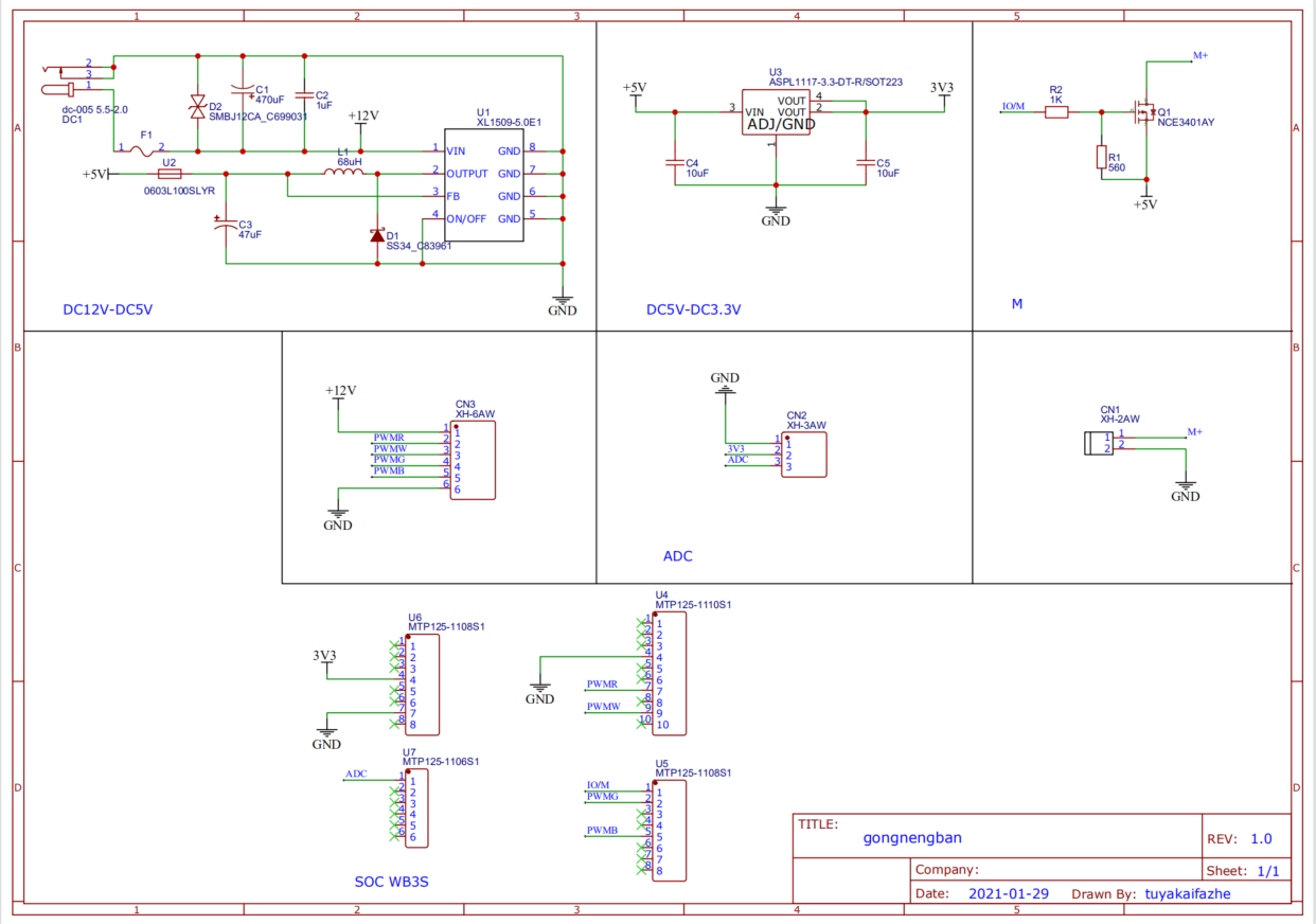
Step 1: Design functional board
We use Tuya Sandwich Wi-Fi SoC master control board (WB3S) as the master control and design a functional board to implement the following functions:
- Provide 12V DC power supply.
- Control the water pump.
- Read analog values from the soil moisture sensor.
- Control the grow light board.
Design description:
-
Circuit diagram (Download)
-
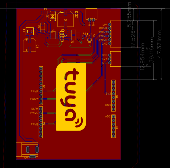
PCB design (Download)
-
PCB layout (Download Gerber file)
-
PCB Coordinate (Download)
Designator Footprint Mid X Mid Y Ref X Ref Y Pad X Pad Y Layer Rotation (°) Comment L1 IND-SMD_L5.0-W5.0-P3.60_SMNR5040 9.02 mm -15.24 mm 9.02 mm -15.24 mm 9.02 mm -17.04 mm T 90 68 μH U2 R0603 30.35 mm -19.94 mm 30.35 mm -19.94 mm 31.11 mm -19.94 mm T 180 0603L100SLYR R2 R0603 45.21 mm -18.41 mm 45.21 mm -18.41 mm 44.46 mm -18.41 mm T 0 1K D2 SMB_L4.6-W3.6-LS5.3-BI 24.26 mm -5.33 mm 24.26 mm -5.33 mm 24.26 mm -2.74 mm T 270 SMBJ12CA_C699031 U5 HDR-TH_8P-P2.54-V 16.33 mm -75.56 mm 16.33 mm -75.56 mm 16.33 mm -66.67 mm T 270 MTP125-1108S1 U6 HDR-TH_8P-P2.54-V 64.59 mm -57.78 mm 64.59 mm -57.78 mm 64.59 mm -48.89 mm T 270 MTP125-1108S1 C1 CAP-SMD_BD10.0-L10.3-W10.3-FD 32.77 mm -6.98 mm 32.77 mm -6.98 mm 32.77 mm -2.79 mm T 90 470 μF U3 SOT-223_L6.5-W3.5-P2.30-LS7.0-BR 38.23 mm -17.65 mm 38.23 mm -17.65 mm 35.37 mm -15.35 mm T 180 ASPL1117-3.3-DT-R/SOT223 CN2 CONN-TH_XH-3AW 61.98 mm -33.53 mm 61.98 mm -33.53 mm 61.98 mm -31.03 mm T 270 XH-3AW F1 F1206 18.8 mm -2.79 mm 18.8 mm -2.79 mm 17.5 mm -2.79 mm T 0 JK-NSMD300L-12V U4 HDR-TH_10P-P2.54-V 16.38 mm -51.18 mm 16.38 mm -51.18 mm 16.38 mm -39.75 mm T 270 MTP125-1110S1 U1 SOIC-8_L5.0-W4.0-P1.27-LS6.0-BL 24.51 mm -17.78 mm 24.51 mm -17.78 mm 21.81 mm -15.87 mm T 270 XL1509-5.0E1 Q1 SOT-23_L2.9-W1.3-P0.95-LS2.4-BR 48.77 mm -17.14 mm 48.77 mm -17.14 mm 47.82 mm -18.34 mm T 270 NCE3401AY DC1 DC-IN-TH_DC005 10.8 mm -95.89 mm 10.8 mm -95.88 mm 13.89 mm -93.53 mm T 0 dc-005 5.5-2.0 CN1 CONN-TH_2P-P2.50_XH-2AW 50 mm -7.75 mm 50 mm -7.75 mm 48.75 mm -7.75 mm T 0 XH-2AW D1 SMA_L4.4-W2.8-LS5.4-RD 17.65 mm -12.83 mm 17.65 mm -12.83 mm 17.65 mm -15.39 mm T 90 SS34_C83961 C2 C0603 40.01 mm -3.43 mm 40.01 mm -3.43 mm 40.01 mm -4.13 mm T 90 1 μF U7 HDR-TH_6P-P2.54-V 64.59 mm -78.1 mm 64.59 mm -78.1 mm 64.59 mm -71.75 mm T 270 MTP125-1106S1 C4 C0603 30.35 mm -18.03 mm 30.35 mm -18.03 mm 29.65 mm -18.03 mm T 0 10 μF C5 C0603 30.35 mm -16.13 mm 30.35 mm -16.13 mm 29.65 mm -16.13 mm T 0 10 μF C3 CAP-SMD_BD8.0-L8.3-W8.3-RD 8.89 mm -24.26 mm 8.89 mm -24.26 mm 8.89 mm -20.96 mm T 270 47 μF CN3 CONN-TH_XH-6AW 61.98 mm -17.02 mm 61.98 mm -17.02 mm 61.98 mm -10.77 mm T 90 XH-6AW R1 R0603 48.64 mm -20.83 mm 48.64 mm -20.83 mm 49.39 mm -20.83 mm T 180 100K -
BOM (Download)
ID Name Designator Footprint Quantity 1 470 μF C1 CAP-SMD_BD10.0-L10.3-W10.3-FD 1 2 1 μF C2 C0603 1 3 47 μF C3 CAP-SMD_BD8.0-L8.3-W8.3-RD 1 4 10 μF C4, C5 C0603 2 5 XH-2AW CN1 CONN-TH_2P-P2.50_XH-2AW 1 6 XH-3AW CN2 CONN-TH_XH-3AW 1 7 XH-6AW CN3 CONN-TH_XH-6AW 1 8 SS34_C83961 D1 SMA_L4.4-W2.8-LS5.4-RD 1 9 SMBJ12CA_C699031 D2 SMB_L4.6-W3.6-LS5.3-BI 1 10 dc-005 5.5-2.0 DC1 DC-IN-TH_DC005 1 11 JK-NSMD300L-12V F1 F1206 1 12 68 μH L1 IND-SMD_L5.0-W5.0-P3.60_SMNR5040 1 13 NCE3401AY Q1 SOT-23_L2.9-W1.3-P0.95-LS2.4-BR 1 14 100K R1 R0603 1 15 1K R2 R0603 1 16 XL1509-5.0E1 U1 SOIC-8_L5.0-W4.0-P1.27-LS6.0-BL 1 17 0603L100SLYR U2 R0603 1 18 ASPL1117-3.3-DT-R/SOT223 U3 SOT-223_L6.5-W3.5-P2.30-LS7.0-BR 1 19 MTP125-1110S1 U4 HDR-TH_10P-P2.54-V 1 20 MTP125-1108S1 U5, U6 HDR-TH_8P-P2.54-V 2 21 MTP125-1106S1 U7 HDR-TH_6P-P2.54-V 1
Step 2: Design grow light board
1. Grow light spectrum
| Spectrum/nm | Plant physiological effects |
|---|---|
| > 1000 | After being absorbed by plants, it will be converted into heat energy to promote dry matter accumulation, without participating in photosynthesis. |
| 720–800 (far infrared) | It promotes the growth and germination of plant cells and controls flowering and fruit color. |
| 720–1000 | It affects plant elongation. |
| 610–720 (red and orange light) | It is strongly absorbed by chlorophyll. Under certain conditions, it shows a strong photoperiod effect. |
| 510–610 (green light) | Chlorophyll does not absorb much, and the photosynthetic efficiency is also low. |
| 400-510 (blue-violet light) | Chlorophyll absorbs the most, showing strong photosynthesis and forming effect. |
| 320–400 (ultraviolet A light) | It plays the role of forming and coloring. |
| 280-320 (ultraviolet) | It is harmful to most plants and may cause plant stomata to close and affect photosynthesis. |
| < 280 (far ultraviolet) | It can kill plants immediately. |
2. Select beads
According to the spectrum characteristics, we choose the following five grow light sources to make the light board.
-
2835 warm white LED (Download specification)
-
2835 red (660 nm) LED (Download specification)
-
2835 blue LED (Download specification)
-
2835 green LED (Download specification)
-
2835 infrared (850 nm) LED (Download specification)
Note: The green light acts as ambient light and rarely affects plant growth. You can choose the beads to suit your preference. Your beads should match the circuit, particularly the red light and infrared parts. The light board schematics and MT7201C related specifications will be helpful.
-
Circuit diagram (Download)
-
PCB design (Download)

-
PCB layout (Download Gerber file)
-
Grow light board PCB coordinate (Download)
Designator Footprint Mid X Mid Y Ref X Ref Y Pad X Pad Y Layer Rotation (°) Comment R1 R0603 -910 mil 315 mil -910 mil 315 mil -910 mil 285.34 mil B -90 0.5 R2 R0603 -910 mil 115 mil -910 mil 115 mil -910 mil 85.34 mil B -90 0.8 R3 R0603 -900 mil -75 mil -900 mil -75 mil -900 mil -104.66 mil B -90 0.8 R4 R0603 -900 mil -280 mil -900 mil -280 mil -900 mil -309.66 mil B -90 0.8 C1 C0603 -840 mil 315 mil -840 mil 315 mil -840 mil 287.44 mil B -90 4.7 μF C2 C0603 -830 mil 115 mil -830 mil 115 mil -830 mil 87.44 mil B -90 4.7 μF C3 C0603 -830 mil -70 mil -830 mil -70 mil -830 mil -97.56 mil B -90 4.7 μF C4 C0603 -830 mil -280 mil -830 mil -280 mil -830 mil -307.56 mil B -90 4.7 μF U1 SOT-89-5_L4.5-W2.5-P1.50-LS4.5-BR -1121.1 mil 314.96 mil -1121.1 mil 314.96 mil -1187.93 mil 374.01 mil B 0 MT7201C U2 SOT-89-5_L4.5-W2.5-P1.50-LS4.5-BR -1121.1 mil 118.11 mil -1121.1 mil 118.11 mil -1187.93 mil 177.16 mil B 0 MT7201C U3 SOT-89-5_L4.5-W2.5-P1.50-LS4.5-BR -1120 mil -75.01 mil -1120 mil -75 mil -1186.83 mil -15.95 mil B 0 MT7201C U4 SOT-89-5_L4.5-W2.5-P1.50-LS4.5-BR -1121.1 mil -275.6 mil -1121.1 mil -275.59 mil -1187.93 mil -216.54 mil B 0 MT7201C C5 C0603 -1355 mil 340 mil -1355 mil 340 mil -1355 mil 312.44 mil B -90 4.7 μF C6 C0603 -1355 mil 145 mil -1355 mil 145 mil -1355 mil 117.44 mil B -90 4.7 μF C7 C0603 -1355 mil -45 mil -1355 mil -45 mil -1355 mil -72.56 mil B -90 4.7 μF C8 C0603 -1355 mil -250 mil -1355 mil -250 mil -1355 mil -277.56 mil B -90 4.7 μF LED31 LED-SMD_L3.5-W2.8-RD_TJ-S2835UG5W8TLC2R-A5 175 mil -375 mil 175 mil -375 mil 219.78 mil -375 mil T 0 2835 850 nm infrared LED LED1 LED-SMD_L3.3-W2.8-RD 1479.83 mil 538.61 mil 1479.83 mil 538.61 mil 1437.01 mil 538.61 mil T 0 2835 warm white LED LED2 LED-SMD_L3.3-W2.8-RD 787.39 mil 1363.82 mil 787.4 mil 1363.82 mil 744.58 mil 1363.82 mil T 0 2835 warm white LED LED3 LED-SMD_L3.3-W2.8-RD -273.47 mil 1550.88 mil -273.46 mil 1550.88 mil -316.28 mil 1550.88 mil T 0 2835 warm white LED LED4 LED-SMD_L3.3-W2.8-RD -1206.37 mil 1012.26 mil -1206.37 mil 1012.26 mil -1249.19 mil 1012.26 mil T 0 2835 warm white LED LED5 LED-SMD_L3.3-W2.8-RD -1574.81 mil 0 mil -1574.8 mil 0 mil -1617.62 mil 0 mil T 0 2835 warm white LED LED6 LED-SMD_L3.3-W2.8-RD -1206.37 mil -1012.26 mil -1206.37 mil -1012.26 mil -1249.19 mil -1012.26 mil T 0 2835 warm white LED LED7 LED-SMD_L3.3-W2.8-RD -273.45 mil -1550.88 mil -273.46 mil -1550.88 mil -230.64 mil -1550.88 mil T 180 2835 warm white LED LED8 LED-SMD_L3.3-W2.8-RD 787.4 mil -1363.82 mil 787.4 mil -1363.82 mil 830.22 mil -1363.82 mil T 180 2835 warm white LED LED9 LED-SMD_L3.3-W2.8-RD 1479.83 mil -538.61 mil 1479.83 mil -538.61 mil 1437.01 mil -538.61 mil T 0 2835 warm white LED D1 SMB_L4.6-W3.6-LS5.3-L-FD 1455 mil 310 mil 1455 mil 310 mil 1368 mil 310 mil T 0 SMBJ12A_C294866 D2 SMB_L4.6-W3.6-LS5.3-L-FD 1455 mil 110 mil 1455 mil 110 mil 1368 mil 110 mil T 0 SMBJ12A_C294866 D3 SMB_L4.6-W3.6-LS5.3-L-FD 1455 mil -85 mil 1455 mil -85 mil 1368 mil -85 mil T 0 SMBJ12A_C294866 D4 SMB_L4.6-W3.6-LS5.3-L-FD 1455 mil -285 mil 1455 mil -285 mil 1368 mil -285 mil T 0 SMBJ12A_C294866 LED16 LED-SMD_L3.5-W2.8-R-RD_TJ-S2835UG5W8TLC6B-A5 755 mil 330 mil 755 mil 330 mil 710.22 mil 330 mil T 180 2835 green LED LED17 LED-SMD_L3.5-W2.8-R-RD_TJ-S2835UG5W8TLC6B-A5 -100 mil 835 mil -100 mil 835 mil -144.78 mil 835 mil T 180 2835 green LED LED18 LED-SMD_L3.5-W2.8-R-RD_TJ-S2835UG5W8TLC6B-A5 -760 mil 335 mil -760 mil 335 mil -715.22 mil 335 mil T 0 2835 green LED LED19 LED-SMD_L3.5-W2.8-R-RD_TJ-S2835UG5W8TLC6B-A5 -755 mil -645 mil -755 mil -645 mil -710.22 mil -645 mil T 0 2835 green LED LED20 LED-SMD_L3.5-W2.8-R-RD_TJ-S2835UG5W8TLC6B-A5 100 mil -1140 mil 100 mil -1140 mil 55.22 mil -1140 mil T 180 2835 green LED LED21 LED-SMD_L3.5-W2.8-R-RD_TJ-S2835UG5W8TLC6B-A5 955 mil -650 mil 955 mil -650 mil 999.78 mil -650 mil T 0 2835 green LED LED10 LED-SMD_L3.5-W2.8-R-RD_TJ-S2835UG5W8TLC6B-A5 950 mil 330 mil 950 mil 330 mil 994.78 mil 330 mil T 0 2835 blue LED LED11 LED-SMD_L3.5-W2.8-R-RD_TJ-S2835UG5W8TLC6B-A5 95 mil 835 mil 95 mil 835 mil 139.78 mil 835 mil T 0 2835 blue LED LED12 LED-SMD_L3.5-W2.8-R-RD_TJ-S2835UG5W8TLC6B-A5 -955 mil 335 mil -955 mil 335 mil -999.78 mil 335 mil T 180 2835 blue LED LED13 LED-SMD_L3.5-W2.8-R-RD_TJ-S2835UG5W8TLC6B-A5 -955 mil -645 mil -955 mil -645 mil -999.78 mil -645 mil T 180 2835 blue LED LED14 LED-SMD_L3.5-W2.8-R-RD_TJ-S2835UG5W8TLC6B-A5 -90 mil -1140 mil -90 mil -1140 mil -134.78 mil -1140 mil T 180 2835 blue LED LED15 LED-SMD_L3.5-W2.8-R-RD_TJ-S2835UG5W8TLC6B-A5 755 mil -650 mil 755 mil -650 mil 710.22 mil -650 mil T 180 2835 blue LED LED22 LED-SMD_L3.5-W2.8-RD_TJ-S2835UG5W8TLC2R-A5 852.39 mil 492.12 mil 852.39 mil 492.13 mil 852.39 mil 536.91 mil T 90 2835 660 nm red LED LED23 LED-SMD_L3.5-W2.8-RD_TJ-S2835UG5W8TLC2R-A5 0 mil 984.26 mil 0 mil 984.25 mil 0 mil 1029.04 mil T 90 2835 660 nm red LED LED24 LED-SMD_L3.5-W2.8-RD_TJ-S2835UG5W8TLC2R-A5 -852.39 mil 492.12 mil -852.39 mil 492.13 mil -852.39 mil 536.91 mil T 90 2835 660 nm red LED LED25 LED-SMD_L3.5-W2.8-RD_TJ-S2835UG5W8TLC2R-A5 -852.39 mil -492.12 mil -852.39 mil -492.13 mil -852.39 mil -447.34 mil T 90 2835 660 nm red LED LED26 LED-SMD_L3.5-W2.8-RD_TJ-S2835UG5W8TLC2R-A5 0 mil -984.26 mil 0 mil -984.25 mil 0 mil -939.47 mil T 90 2835 660 nm red LED LED27 LED-SMD_L3.5-W2.8-RD_TJ-S2835UG5W8TLC2R-A5 852.39 mil -492.12 mil 852.39 mil -492.13 mil 852.39 mil -447.34 mil T 90 2835 660 nm red LED LED29 LED-SMD_L3.5-W2.8-RD_TJ-S2835UG5W8TLC2R-A5 170 mil 360 mil 170 mil 360 mil 214.78 mil 360 mil T 0 2835 850 nm infrared LED LED30 LED-SMD_L3.5-W2.8-RD_TJ-S2835UG5W8TLC2R-A5 -393.7 mil 0 mil -393.7 mil 0 mil -438.48 mil 0 mil T 180 2835 850 nm infrared LED CN3 CONN-TH_XH-6AW 1653.54 mil 0 mil 1653.54 mil 0 mil 1653.54 mil 246.1 mil T 90 XH-6AW L1 IND-SMD_L3.5-W3.0_GSDR32P 1200 mil 305 mil 1200 mil 305 mil 1148.82 mil 305 mil T 0 47 μH L2 IND-SMD_L3.5-W3.0_GSDR32P 1200 mil 108.15 mil 1200 mil 108.15 mil 1148.82 mil 108.15 mil T 0 47 μH L3 IND-SMD_L3.5-W3.0_GSDR32P 1200 mil -88.7 mil 1200 mil -88.7 mil 1148.82 mil -88.7 mil T 0 47 μH L4 IND-SMD_L3.5-W3.0_GSDR32P 1200 mil -285.55 mil 1200 mil -285.55 mil 1148.82 mil -285.55 mil T 0 47 μH -
BOM (Download)
ID Name Designator Footprint Quantity 1 4.7 μF C1, C2, C3, C4 C0603 4 2 4.7 μF C5, C6, C7, C8 C0603 4 3 XH-6AW CN3 CONN-TH_XH-6AW 1 4 SMBJ12A_C294866 D1, D2, D3, D4 SMB_L4.6-W3.6-LS5.3-L-FD 4 5 47 μH L1, L2, L3, L4 IND-SMD_L3.5-W3.0_GSDR32P 4 6 2835 warm white LED LED1, LED2, LED3, LED4, LED5, LED6, LED7, LED8, LED9 LED-SMD_L3.3-W2.8-RD 9 7 2835 blue LED LED10, LED11, LED12, LED13, LED14, LED15 LED-SMD_L3.5-W2.8-R-RD_TJ-S2835UG5W8TLC6B-A5 6 8 2835 green LED LED16, LED17, LED18, LED19, LED20, LED21 LED-SMD_L3.5-W2.8-R-RD_TJ-S2835UG5W8TLC6B-A5 6 9 2835 660 nm red LED LED22, LED23, LED24, LED25, LED26, LED27 LED-SMD_L3.5-W2.8-RD_TJ-S2835UG5W8TLC2R-A5 6 10 2835 850 nm infrared LED LED29, LED30, LED31 LED-SMD_L3.5-W2.8-RD_TJ-S2835UG5W8TLC2R-A5 3 11 0.5 R1 R0603 1 12 0.8 R2, R3, R4 R0603 3 13 M3 brass standoff TP1, TP2, TP3, TP4 M3 brass standoff 4 14 MT7201C U1, U2, U3, U4 SOT-89-5_L4.5-W2.5-P1.50-LS4.5-BR 4
Step 3: Design fixture and container
1. C-shape light fixture
Cut 8 mm acrylic sheet, heat it to a degree of softness, and bend it to the desired shape.

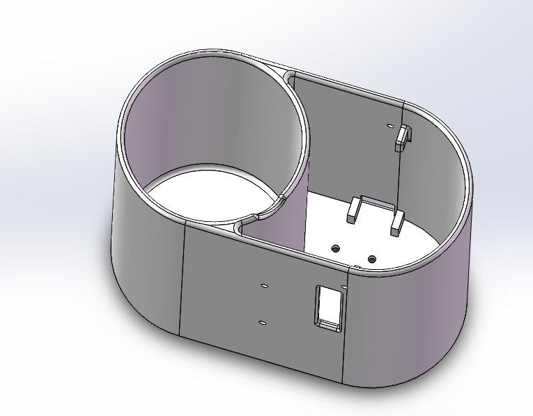
2. Water tank 3D printing
The water tank is divided into two compartments, one for storing water and the other for placing PCBs. We use polylactide (PLA) to 3D print this water tank.
-
Water reservoir lid (Download STL file)

-
Water tank body lid (Download STL file)

-
Water tank body (Download STL file)
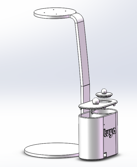
3. Finish assembly
Step 4: Prepare materials
You can find them in the Materials part.
Step 5: Prototype on Tuya IoT Platform
To proceed with TuyaOS development, you need to create an indoor garden product on the Tuya IoT Platform and then get the SDK. This product represents all the IoT functions of a smart garden, including product authorization and configuration, which builds the communication between the garden and the Tuya IoT Platform. This section describes how to create a smart indoor garden on the Tuya IoT Platform. For more information, see Create Products.
-
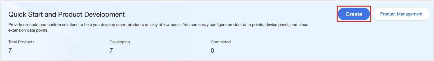
Log in to the Tuya IoT Platform, and click Create.
-
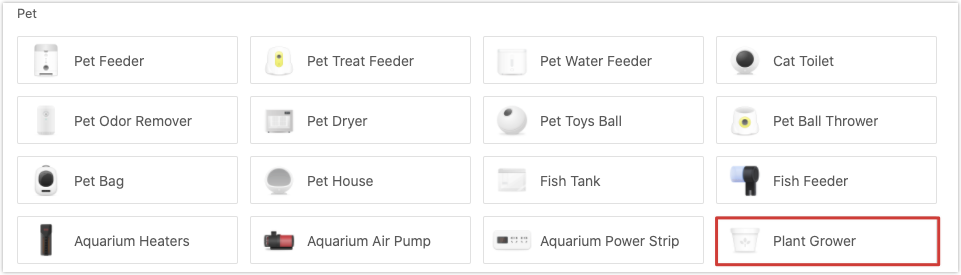
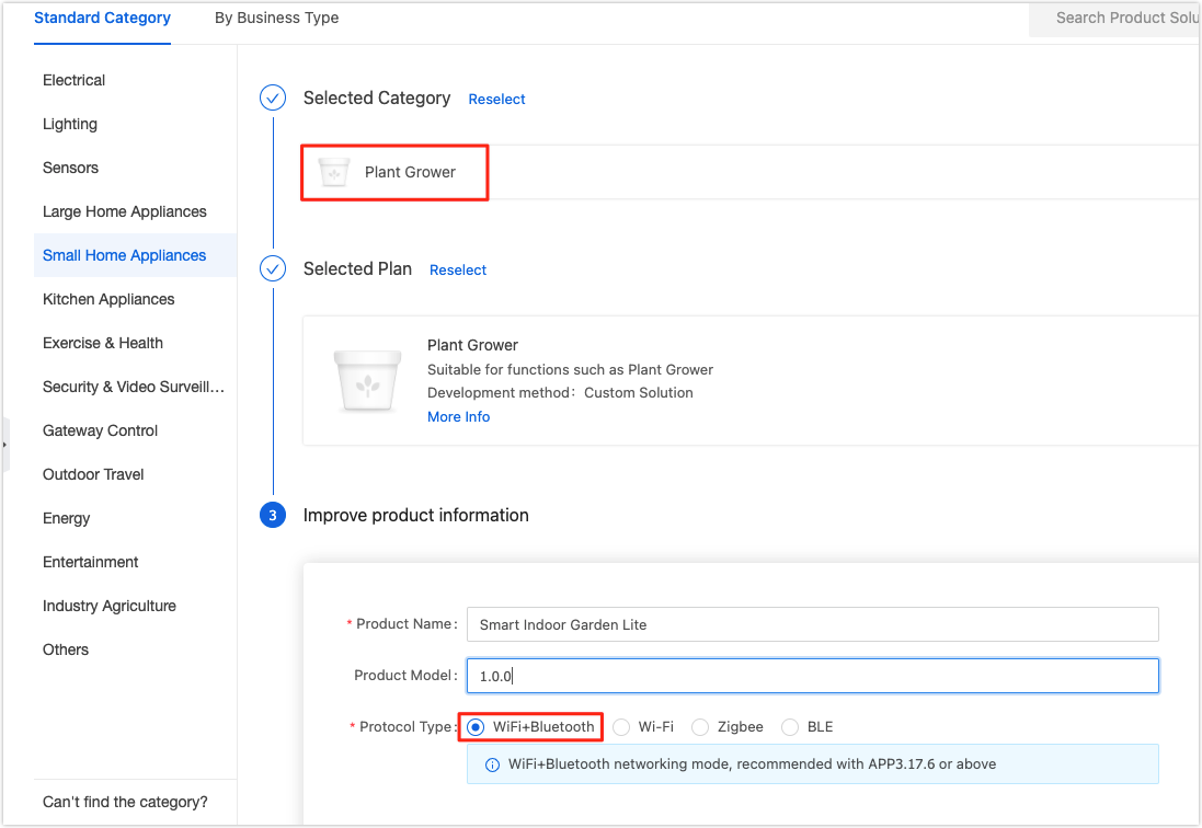
Select Small Home Appliances > Plant Grower.
-
Click Custom Solution > Plant Grower. Enter a product name, select WiFi+Bluetooth for protocol type, and click Create Product at the bottom of this page.
-
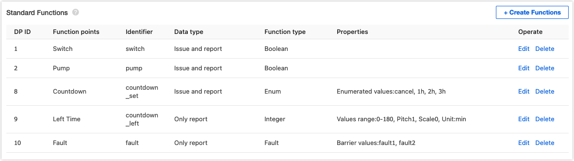
In Create Standard Functions, select Switch, Pump, Countdown, Left Time, and Fault. The function name and specific enum values can be customized.
-
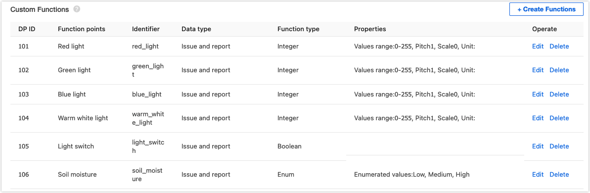
Find Custom Functions and click Create Functions. Set properties for a custom function. For the specific property value, see the following figure. To implement the non-standard functions of a smart garden, you need to customize some functions.
-
Add four custom functions, Red light, Green light, Blue light, and Warm white light, to adjust the brightness of the grow light.
-
Add Light switch of Boolean type to turn on or off the light.
-
Add Soil moisture of enum type to set a threshold for triggering auto watering.
-
-
When you complete function definition, click Device Panel to select a favorite app control panel. It is recommended to select the Debug Panel to suit your debugging needs.
You have finished creating a product on the Tuya IoT Platform. It is ready to proceed with embedded system development.
Step 6: Coding
The embedded code is based on the BK7231 chipset and developed with Tuya’s general Wi-Fi SDK. You can download the demo routine and find the sample code.
1. Entry to application
The apps folder contains application code. The structure of the application code is as follows:
├── src
|    ├── plant_driver
|    |      └── plant_pwm.c      // PWM driver. The PWM API on the SoC layer is called and re-encapsulated.
|    ├── plant_soc               // APIs running on the SoC layer
|    ├── tuya_device.c           // Entry file of application layer
|    ├── app_plant.c             // The application layer
|    └── plant_control.c         // Control logic of each functional component
|
├── include				// Header file directory
|    ├── plant_driver
|    |      └── plant_pwm.h
|    ├── plant_soc
|    ├── tuya_device.h
|    ├── app_plant.h
|    └── plant_control.h
|
└── output              // Production
Open tuya_device.c and find the device_init function.
OPERATE_RET device_init(VOID)
{
  OPERATE_RET op_ret = OPRT_OK;

  UCHAR_T connect_mode = 0;

  PR_NOTICE("goto device_init!!!");

  TY_IOT_CBS_S wf_cbs = {
      status_changed_cb,\
      gw_ug_inform_cb,\
      gw_reset_cb,\
      dev_obj_dp_cb,\
      dev_raw_dp_cb,\
      dev_dp_query_cb,\
      NULL,
  };

  connect_mode = GWCM_OLD;

  op_ret = tuya_iot_wf_soc_dev_init_param(connect_mode,WF_START_SMART_FIRST,&wf_cbs,NULL,PRODECT_KEY,DEV_SW_VERSION);

  if(OPRT_OK != op_ret) {
      PR_ERR("tuya_iot_wf_soc_dev_init_param error,err_num:%d",op_ret);
      return op_ret;
  }

  op_ret = tuya_iot_reg_get_wf_nw_stat_cb(wf_nw_status_cb);
  if(OPRT_OK != op_ret) {
      PR_ERR("tuya_iot_reg_get_wf_nw_stat_cb is error,err_num:%d",op_ret);
      return op_ret;
  }

  op_ret = app_plant_init(APP_PLANT_NORMAL);
  if(OPRT_OK != op_ret) {
      PR_ERR("plant init err!");
      return op_ret;
  }

  return op_ret;
}
In the development environment for the BK7231T chipset, the device_init function is the entry to the application code. When the device is powered on, the adaptation layer runs the initialization code and then calls this function to initialize the application layer. This function deals with the followings:
-
Call
tuya_iot_wf_soc_dev_init_param()for SDK initialization to configure working mode and pairing mode, register callback functions, and save the firmware key and PID. The macro definition for PID isPRODECT_KEYin code.TY_IOT_CBS_S wf_cbs = { status_changed_cb,\ gw_ug_inform_cb,\ gw_reset_cb,\ dev_obj_dp_cb,\ dev_raw_dp_cb,\ dev_dp_query_cb,\ NULL, }; connect_mode = GWCM_OLD; op_ret = tuya_iot_wf_soc_dev_init_param(connect_mode,WF_START_SMART_FIRST,\ &wf_cbs,NULL,PRODECT_KEY,DEV_SW_VERSION); if(OPRT_OK != op_ret) { PR_ERR("tuya_iot_wf_soc_dev_init_param error,err_num:%d",op_ret); return op_ret; } -
Call
tuya_iot_reg_get_wf_nw_stat_cb()to register callback of device network status.op_ret = tuya_iot_reg_get_wf_nw_stat_cb(wf_nw_status_cb); if(OPRT_OK != op_ret) { PR_ERR("tuya_iot_reg_get_wf_nw_stat_cb is error,err_num:%d",op_ret); return op_ret; } -
Call the initialization function in the application layer.
    op_ret = app_plant_init(APP_PLANT_NORMAL);
    if(OPRT_OK != op_ret) {
        PR_ERR("plant init err!");
        return op_ret;
    }
2. Application architecture
The application code is implemented in three layers.
- The bottom layer contains the driver code of PWM and sensors and encapsulates APIs for sensor initialization and data collection. In this project, we only use a soil moisture sensor whose analog output is processed using ADC, so only the PWM API on this layer will be called.
- The second layer has part of control logic code and calls sensor driver API to implement the control logic of each component. This layer packages API of polling data processing.
- The first layer creates application tasks to call the API in the second layer, processes DP data transmission, and accepts parsing.
app_plant.c implements the first layer.
-
app_plant_init()calls device initialization API packaged in the second layer and creates application tasks.OPERATE_RET app_plant_init(IN APP_PLANT_MODE mode) { OPERATE_RET op_ret = OPRT_OK; if(APP_PLANT_NORMAL == mode) { // Initialize I/O, sensors, PWM, and more plant_device_init(); // Create data collection tasks for ADC sensors tuya_hal_thread_create(NULL, "thread_data_get_adc", 512*4, TRD_PRIO_4, sensor_data_get_adc_theard, NULL); // Create data processing tasks tuya_hal_thread_create(NULL, "thread_data_deal", 512*4, TRD_PRIO_4, sensor_data_deal_theard, NULL); // Create scheduled tasks for DP data reporting tuya_hal_thread_create(NULL, "thread_data_report", 512*4, TRD_PRIO_4, sensor_data_report_theard, NULL); }else { // Non-production test mode } return op_ret; } -
app_report_all_dp_status()reports all DP data.VOID app_report_all_dp_status(VOID) { OPERATE_RET op_ret = OPRT_OK; INT_T dp_cnt = 0; dp_cnt = 12; TY_OBJ_DP_S *dp_arr = (TY_OBJ_DP_S *)Malloc(dp_cnt*SIZEOF(TY_OBJ_DP_S)); if(NULL == dp_arr) { PR_ERR("malloc failed"); return; } memset(dp_arr, 0, dp_cnt*SIZEOF(TY_OBJ_DP_S)); dp_arr[0].dpid = DPID_SWITCH_P; dp_arr[0].type = PROP_BOOL; dp_arr[0].time_stamp = 0; dp_arr[0].value.dp_value = plant_ctrl_data.Switch; ...... op_ret = dev_report_dp_json_async(NULL,dp_arr,dp_cnt); Free(dp_arr); if(OPRT_OK != op_ret) { PR_ERR("dev_report_dp_json_async relay_config data error,err_num",op_ret); } PR_DEBUG("dp_query report_all_dp_data"); return; } -
In a task,
plant_get_adc_sensor_data(),plant_ctrl_handle(), andplant_ctrl_all_off()are APIs on the second layer, which are implemented inplant_control.cfile.STATIC VOID sensor_data_get_adc_theard(PVOID_T pArg) { while(1) { PR_DEBUG("plant_get_adc_sensor_data"); tuya_hal_system_sleep(TASKDELAY_SEC*2); if(TRUE == plant_ctrl_data.Switch) { plant_get_adc_sensor_data(); } } } STATIC VOID sensor_data_deal_theard(PVOID_T pArg) { while(1) { tuya_hal_system_sleep(TASKDELAY_SEC); if(TRUE == plant_ctrl_data.Switch) { plant_ctrl_handle(); }else { plant_ctrl_all_off(); } } } STATIC VOID sensor_data_report_theard(PVOID_T pArg) { while(1) { tuya_hal_system_sleep(TASKDELAY_SEC*5); app_report_all_dp_status(); } } -
deal_dp_proc()processes the received DP data according to the DP ID.VOID deal_dp_proc(IN CONST TY_OBJ_DP_S *root) { UCHAR_T dpid; dpid = root->dpid; PR_DEBUG("dpid:%d",dpid); switch (dpid) { case DPID_SWITCH_P: PR_DEBUG("set switch:%d",root->value.dp_bool); plant_ctrl_data.Switch = root->value.dp_bool; break; case DPID_PUMP: PR_DEBUG("set pump:%d",root->value.dp_bool); plant_ctrl_data.Pump = root->value.dp_bool; break; ...... default: break; } return; }
We have built the application architecture. And next, we need to implement API in the second layer, which is placed in plant_control.c. Next, we will see how to implement each function.
3. Lighting control
Dim the warm white and multi-color light with an app to provide the spectrum needed for plant growth.
The PWM output controls light brightness. The PWM initialization and output functions are implemented in plant_pwm.c. Initialize PWM in plant_device_init() and call the API to implement light control in plant_ctrl_handle().
USER_PWM_DUTY_T user_pwm_duty = {0};

VOID plant_device_init(VOID)
{
    ......
    plant_pwm_init();
    ......
}

STATIC VOID __set_pwm_duty(VOID)
{
    user_pwm_duty.duty_red = (USHORT_T)(((float)plant_ctrl_data.Red_value/255.0)*1000);
    user_pwm_duty.duty_green = (USHORT_T)(((float)plant_ctrl_data.Green_value/255.0)*1000);
    user_pwm_duty.duty_blue = (USHORT_T)(((float)plant_ctrl_data.Blue_value/255.0)*1000);
    user_pwm_duty.duty_warm = (USHORT_T)(((float)plant_ctrl_data.Warm_value/255.0)*1000);
}

STATIC VOID __initiative_ctrl_module_light(VOID)
{
    if (plant_ctrl_data.Countdown_set != cancel)
    {
        if(IsThisSysTimerRun(light_timer) == FALSE) {
            light_flag_min = (USHORT_T)plant_ctrl_data.Countdown_set * 60;
            plant_pwm_set(&user_pwm_duty);
            sys_start_timer(light_timer,1000*60,TIMER_CYCLE);
        }else {
            plant_pwm_set(&user_pwm_duty);
        }
    }else {
        light_flag_min = 0;
        if(TRUE == plant_ctrl_data.Light_switch) {
            plant_pwm_set(&user_pwm_duty);
        }else {
            plant_pwm_off();
        }
    }
    plant_report_data.Countdown_left = light_flag_min;
}

VOID plant_ctrl_handle(VOID)
{
    ......
    __set_pwm_duty();
    __initiative_ctrl_module_light();
}
4. Spraying
The soil moisture sensor outputs different analog signal values according to the change of soil resistance. The ADC converts analog signals from the sensor into digital signals to monitor the change of moisture.
In app_plant.c, the ADC collection task calls plant_get_adc_sensor_data() in plant_control.c in a loop. All ADC collection related code is placed in this API:
VOID plant_get_adc_sensor_data(VOID)
{
    tuya_hal_adc_init(&tuya_adc);

    tuya_hal_adc_value_get(TEMP_ADC_DATA_LEN, &soil_moisture_value);

    PR_NOTICE("water_tank_value = %d",soil_moisture_value);

    tuya_hal_adc_finalize(&tuya_adc);
}
The functional board compares the obtained soil moisture value with the threshold and determines whether to water plants. You can set the threshold on the app. Manual watering is also possible. Just enable Pump on the app to supply water to your plants.
Call the watering control API in plant_ctrl_handle(). The ADD_WATER_COUNT and ADD_WATER_READY variables enable a rest-interval for the water pump to avoid overwatering plants.
STATIC VOID __passive_ctrl_module_soil_humidity(VOID)
{
    if(!ADD_WATER_READY) {
        tuya_gpio_write(WATER_PUMP_PORT, WATER_PUMP_LEVEL);
        ADD_WATER_COUNT++;
        if(ADD_WATER_COUNT >15) {
            ADD_WATER_READY = 1;
            ADD_WATER_COUNT = 0;
        }
    }

    switch (plant_ctrl_data.soil_moisture_level) {

    case manual_control:
        ADD_WATER_COUNT == 0;
        ADD_WATER_READY == 1;
        break;
    case low:
        if(soil_moisture_value > soil_moisture_threshold.Low) {
            if(ADD_WATER_READY) {
                tuya_gpio_write(WATER_PUMP_PORT, !WATER_PUMP_LEVEL);
                ADD_WATER_COUNT++;
                if(ADD_WATER_COUNT > 2) {
                    ADD_WATER_READY = 0;
                }
            }
        }else {
            tuya_gpio_write(WATER_PUMP_PORT, WATER_PUMP_LEVEL);
        }
        break;
    case medium:
        if(soil_moisture_value > soil_moisture_threshold.Medium) {
            if(ADD_WATER_READY) {
                tuya_gpio_write(WATER_PUMP_PORT, !WATER_PUMP_LEVEL);
                ADD_WATER_COUNT++;
                if(ADD_WATER_COUNT > 2) {
                    ADD_WATER_READY = 0;
                }
            }
        }else {
            tuya_gpio_write(WATER_PUMP_PORT, WATER_PUMP_LEVEL);
        }
        break;
    case high:
        if(soil_moisture_value > soil_moisture_threshold.High) {
            if(ADD_WATER_READY) {
                tuya_gpio_write(WATER_PUMP_PORT, !WATER_PUMP_LEVEL);
                ADD_WATER_COUNT++;
                if(ADD_WATER_COUNT > 2) {
                    ADD_WATER_READY = 0;
                }
            }
        }else {
            tuya_gpio_write(WATER_PUMP_PORT, WATER_PUMP_LEVEL);
        }
        break;
    default:
        break;
    }
}

STATIC VOID __initiative_ctrl_module_pump(VOID)
{
    if(plant_ctrl_data.soil_moisture_level != manual_control) {
        return;
    }

    if(TRUE == plant_ctrl_data.Pump) {
        tuya_gpio_write(WATER_PUMP_PORT, !WATER_PUMP_LEVEL);
    }else {
        tuya_gpio_write(WATER_PUMP_PORT, WATER_PUMP_LEVEL);
    }

}

VOID plant_ctrl_handle(VOID)
{
    ......
    // Automatic control of the water pump
    __passive_ctrl_module_pump();
	// Manual control of the water pump
    __initiative_ctrl_module_pump();
    ......
}
Now, we have completed the coding part. After testing DP data transmission with the debugging panel on the app, we can proceed with firmware building.
5. Build and flash firmware
In Linux terminal, run build_app.sh script to build firmware. The generated firmware is located in apps > APP_PATH > output.
-
Command format:
build_app.sh <APP_PATH> <APP_NAME> <APP_VERSION> -
Sample command:
/home/share/samba/ci/ty_iot_wf_bt_sdk_bk7231t$ sudo sh build_app.sh apps/bk7231t_plant_grow_mach_demo bk7231t_plant_grow_mach_demo 1.0.0 -
The following figures show a successful return.
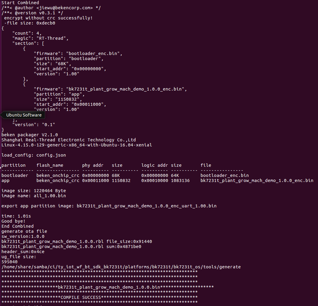
After flashing firmware to the module, we move to functional debugging. For more information about flashing and authorization, see WB Serial Module Burning and Authorizing.
Step 7: Device control
1. Pair device
-
Download the Tuya Smart app from app stores such as App Store.
-
Open the Tuya Smart app and click the + icon in the upper right corner to add a device.

-
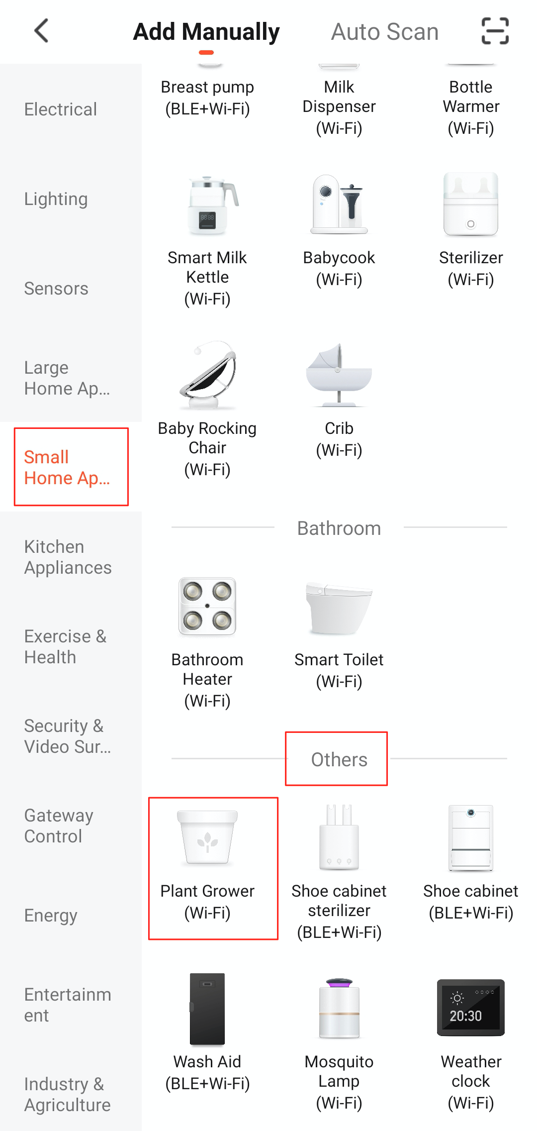
Select Small Home Appliances > Others > Plant Grower.
-
Select your Wi-Fi network and enter the Wi-Fi password.
-
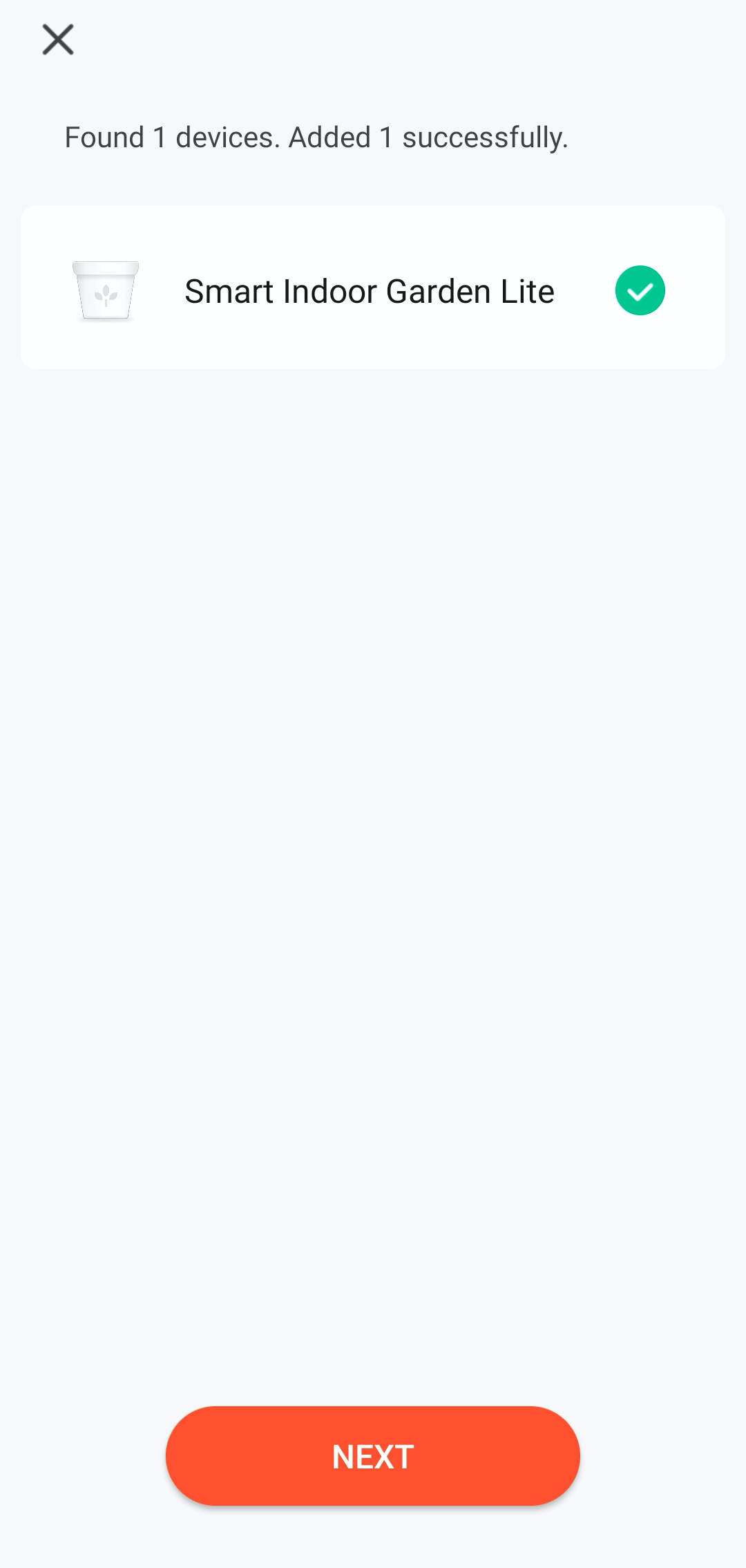
Wait for pairing.
2. Clear pairing information
In case of changing an associated account, initializing the device, and forgetting pairing information or account, you can clear the pairing information to solve these problems.
Method 1: Remove the device on the Tuya Smart app
- Open the Tuya Smart app.
- Long press any device in the device list, select the plant grower you have added, and tap Remove Device.
Method 2: Power on and off the device three times
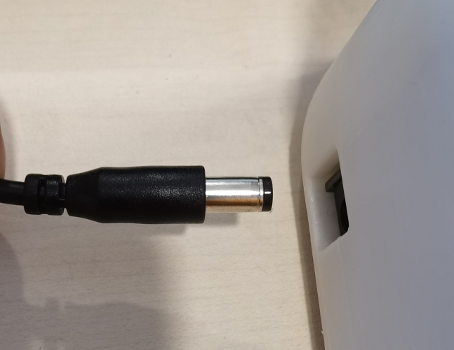
Plug in the power cord for your plant grower, wait for the light board to turn white, and unplug the power cord. Repeat this operation three times.
Summary
Congratulations! You have successfully prototyped a smart indoor garden. Backed by the Tuya IoT Platform, you can explore more projects that come in handy in real-life scenarios.
Is this page helpful?
YesSuggestions


