WBRV 模组规格书
WBRV 是由涂鸦智能开发的一款低功耗嵌入式 Wi-Fi + 蓝牙的语音模组。它由一个高集成度的无线射频芯片 RTL8720CF-VU2+CI1302 构成,内置了 Wi-Fi 网络协议栈和丰富的库函数。
产品概述
WBRV 是支持语音控制的 Wi-Fi AI 模组,集成涂鸦 AI 平台,可以通过语音交互,并通过涂鸦 AI Agent 连接各大 AI 平台,支持豆包、DeepSeek、通义千问、OpenAI、Gemini 等大模型。支持按键唤醒、唤醒词唤醒、随意对话等功能,可以为用户提供生动有趣的 AI 语音交互体验,适用于语音交互场景的智能产品。
WBRV 包含低功耗的 KM4 MCU、WLAN MAC、1T1R WLAN,最高主频 100 MHz,内置 384K SRAM ,芯片内置 4 Mbyte flash 和丰富的外设资源。
WBRV 是一个 RTOS 平台,集成了所有 Wi-Fi MAC 以及 TCP/IP 协议的函数库。用户可以基于这些开发满足自己需求的嵌入式 Wi-Fi 产品。
特性
- 内置低功耗 KM4 MCU,可以兼作应用处理器
- 主频 100 MHz
- 工作电压:3.6 V - 5.5 V
- 外设:11×GPIOs、1×UART(5V)和 1×Log_UART、1xMIC 接口、1xSpeaker 接口
- Wi-Fi/蓝牙连通性
- 802.11 B/G/N20
- 通道 1-14@2.4GHz(CH1-11 for US/CA, CH1-13 for EU/CN)
- 支持 WPA2/WPA2 PSK(AES)安全模式
- 支持 Bluetooth 5.4 Low Energy
- 802.11 B 模式下 +17.5 dBm 的输出功率
- 支持 SmartConfig 功能,包括 Android 和 iOS 设备
- 板载 PCB Onboard 天线
- 通过 CE 和 FCC 认证
- 工作温度:-40℃ 到 85℃
应用领域
- 智慧楼宇
- 智慧家居
- 智能插座
- 智能灯具
- 智能公交
- 工业无线控制
- 婴儿监控器
- 网络摄像头
模组接口
尺寸封装
-
WBRV 共有 3 排引脚,引脚间距为 1.4 mm。
-
WBRV 尺寸大小:18 ± 0.35 mm (W) × 30.2 ± 0.35 mm (L) × 3.0 ± 0.15 mm (H)。WBRV 尺寸图如下图所示:
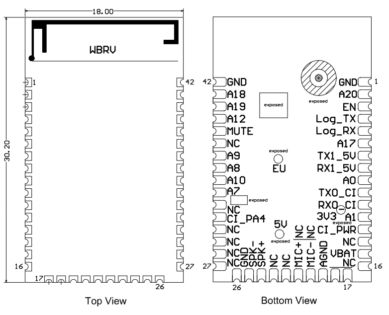
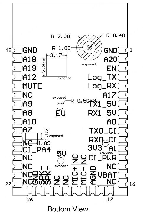
引脚定义
| 引脚 | 符号 | I/O 类型 | 功能 |
|---|---|---|---|
| 1 | GND | P | 电源参考地 |
| 2 | A20 | I/O | GPIOA_20,硬件 PWM,IC Pin1 |
| 3 | EN | I/O | 模组使能引脚,低电平有效,模组已上拉高电平,用户可外部控制该引脚 |
| 4 | Log_TX | I/O | GPIOA_16,UART_Log_TX(用于输出串口信息),可配置成普通 GPIO |
| 5 | Log_TX | I/O | GPIOA_15,UART_Log_RX(用于接收串口信息),可配置成普通 GPIO |
| 6 | A17 | I/O | GPIOA_17,硬件 PWM,IC Pin38 |
| 7 | TX1_5V | I/O | GPIOA_14,UART1_TXD(MCU 对接串口),5 V 电平 |
| 8 | RX1_5V | I/O | GPIOA_13,UART1_RXD(MCU 对接串口),5 V 电平 |
| 9 | A0 | I/O | GPIOA_0,通用 IO,启动时拉高进入烧录模式,外部不能上拉使用,IC Pin15 |
| 10 | TX0_CI | I/O | 语音芯片烧录串口 TX0 |
| 11 | RX0_CI | I/O | 语音芯片烧录串口 RX0 |
| 12 | A1 | I/O | GPIOA_1,启动时拉高进入测试模式,外部不能上拉使用,IC Pin16 |
| 13 | CI_PWR | P | 语音芯片电源控制使能,高电平有效,对应 RTL8720CF 的 A11 |
| 14 | NC | - | NC |
| 15 | VBAT | P | 模组电源输入引脚,电源范围 3.6 V - 5.5 V |
| 16 | NC | - | NC |
| 17 | NC | - | NC |
| 18 | NC | - | NC |
| 19 | AGND | P | 模组模拟地 |
| 20 | MIC- | AI | 麦克风输入 Negative input |
| 21 | MIC+ | AI | 麦克风输入 Positive input |
| 22 | NC | - | NC |
| 23 | NC | - | NC |
| 24 | SPK+ | AO | 音频输出 Positive output |
| 25 | SPK- | AO | 音频输出 Negative output |
| 26 | GND | P | 模组地 |
| 27 | NC | - | NC |
| 28 | NC | - | NC |
| 29 | NC | - | NC |
| 30 | NC | - | NC |
| 31 | CI_PA4 | I/O | 语音芯片调试引脚,用户禁止使用 |
| 32 | NC | - | NC |
| 33 | A7 | I/O | GPIOA_7,普通 GPIO,IC Pin21,可以复用为 SPI_CS |
| 34 | A10 | I/O | GPIOA_10,普通 GPIO,IC Pin24,可以复用为 SPI_MISO |
| 35 | A8 | I/O | GPIOA_8,普通 GPIO,IC Pin22,可以复用为 SPI_SCK |
| 36 | A9 | I/O | GPIOA_9,普通 GPIO,IC Pin23,可以复用为 SPI_MOSI |
| 37 | NC | - | NC |
| 38 | MUTE | O | 内置音频功放的使能引脚,用户禁止使用 |
| 39 | A12 | I/O | GPIOA_12,硬件 PWM,IC Pin26 |
| 40 | A19 | I/O | GPIOA_19,硬件 PWM,IC Pin40 |
| 41 | A18 | I/O | GPIOA_18,硬件 PWM,IC Pin39 |
| 42 | GND | P | 模组地 |
P 表示电源引脚,I/O 表示输入输出引脚。
电气参数
绝对电气参数
| 参数 | 描述 | 最小值 | 最大值 | 单位 |
|---|---|---|---|---|
| Ts | 存储温度 | -55 | 125 | ℃ |
| VBAT | 供电电压 | -0.3 | 5.5 | V |
| 静电释放电压(人体模型) | TAMB-25℃ | - | 2 | KV |
| 静电释放电压(机器模型) | TAMB-25℃ | - | 0.5 | KV |
工作条件
| 参数 | 描述 | 最小值 | 典型值 | 最大值 | 单位 |
|---|---|---|---|---|---|
| Ta | 工作温度 | -40 | - | 85 | ℃ |
| VBAT | 工作电压 | 3.6 | - | 5.5 | V |
| VIL | I/O 低电平输入 | - | - | 0.8 | V |
| VIH | I/O 高电平输入 | 2.0 | - | - | V |
| VOL | I/O 低电平输出 | - | - | 0.4 | V |
| VOH | I/O 高电平输出 | 2.4 | - | - | V |
| Imax | I/O 驱动电流 | - | - | 16 | mA |
| Cpad | 输入引脚电容 | - | 2 | - | pF |
射频功耗
-
TX 连续发送时功耗:
符号 模式 功率 平均值 峰值(典型值) 单位 IRF 11 B 11 Mbps 17 dBm 217 268 mA IRF 11 B 11 Mbps 18 dBm 231 283 mA IRF 11 G 54 Mbps 15 dBm 159 188 mA IRF 11 G 54 Mbps 17.5 dBm 177 213 mA IRF 11 N BW20 MCS7 13 dBm 145 167 mA IRF 11 N BW20 MCS7 16.5 dBm 165 193 mA -
RX 连续接收时功耗:
符号 模式 平均值 峰值(典型值) 单位 IRF 11 B 11 Mbps 63 65 mA IRF 11 G 54 Mbps 65 67 mA IRF 11 N HT20 MCS7 65 67 mA
工作功耗
| 工作模式 | 工作状态,TA=25℃ | 平均值 | 峰值(典型值) | 单位 |
|---|---|---|---|---|
| 快连配网状态(蓝牙配网) | 模组处于快连配网状态,Wi-Fi 指示灯快闪 | 61 | 272 | mA |
| 快连配网状态(AP 配网) | 模组处于热点配网状态,Wi-Fi 指示灯慢闪 | 59 | 272 | mA |
| 快连配网状态(AP 配网) | 模组处于快连配网状态,Wi-Fi 指示灯快闪 | 62 | 280 | mA |
| 网络连接空闲状态 | 模组处于联网工作状态,Wi-Fi 指示灯常亮 | 51 | 260 | mA |
| 网络连接操作状态 | 模组处于联网工作状态,Wi-Fi 指示灯常亮 | 59 | 268 | mA |
| 弱网连接状态 | 模组和热点处于弱网连接状态,Wi-Fi 指示灯常亮 | 62 | 264 | mA |
| 网络断连状态 | 模组处于断网工作状态,Wi-Fi 指示灯常灭 | 57 | 268 | mA |
| 模组 Disable 状态 | 模组处于 EN 拉低状态 | 1.5 | 1.6 | mA |
射频参数
基本射频特性
| 参数项 | 详细说明 |
|---|---|
| 频率范围 | 2.400~2.4835 GHz |
| Wi-Fi 标准 | IEEE 802.11 B/G/N(通道 1-14) |
| 蓝牙标准 | 蓝牙 5.4 |
| 数据传输速率 | 11 B:1、2、5.5、11 Mbps |
| 数据传输速率 | 11 G:6、9、12、18、24、36、48、54 Mbps |
| 数据传输速率 | 11 N:HT20 MCS0-7 |
| 天线类型 | PCB 天线,Peak 增益 1.25 dBi |
发射性能
-
TX 连续发送性能:
参数项 最小值 典型值 最大值 单位 RF 平均输出功率,802.11 B CCK Mode 1 Mbps - 17.5 - dBm RF 平均输出功率,802.11 G OFDM Mode 54 Mbps - 14.5 - dBm RF 平均输出功率,802.11 N OFDM Mode MCS7 - 13.5 - dBm RF 平均输出功率,蓝牙 5.4 1 Mbps - 6.5 - dBm 频率误差 -20 - 20 ppm EVM@802.11 B CCK 11 Mbps Mode 17.5 dBm - - -10 dB EVM@802.11 G OFDM 54 Mbps Mode 14.5 dBm - - -29 dB EVM@802.11 N OFDM MCS7 Mode 13.5 dBm - - -30 dB
-
接收性能:
参数项 最小值 典型值 最大值 单位 PER<8%,RX 灵敏度,802.11 B CCK Mode 1 Mbps - -97 - dBm PER<10%,RX 灵敏度,802.11 G OFDM Mode 54 Mbps - -75 - dBm PER<10%,RX 灵敏度,802.11 N OFDM Mode MCS7 - -72 - dBm PER<10%,RX 灵敏度, 蓝牙 5.4 1 Mbps - -93 - dBm
天线信息
天线类型
只有 PCB 板载天线接入方式,天线 Peak 增益 1.25 dBi。
降低天线干扰
在 Wi-Fi 模组上使用 PCB 板载天线时,为确保 Wi-Fi 性能的最优化,建议模组天线部分和其他金属件距离至少在 15 mm 以上。
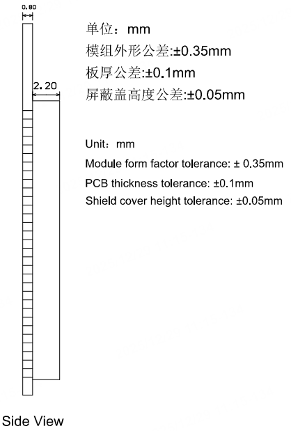
封装信息及生产指导
机械尺寸
WBRV 的 PCB 机械尺寸大小:18 ± 0.35 mm (W) × 30.2 ± 0.35 mm (L) × 0.8 ± 0.1 mm (H)。WBRV 的机械尺寸如下图所示。
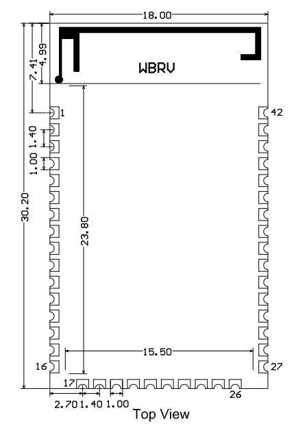
默认的尺寸公差为 ± 0.35 mm,关键尺寸如果客户有明确要求,请沟通后在规格书中进行明确的标定。
PCB 推荐封装
WBRV 原理图引脚对应图
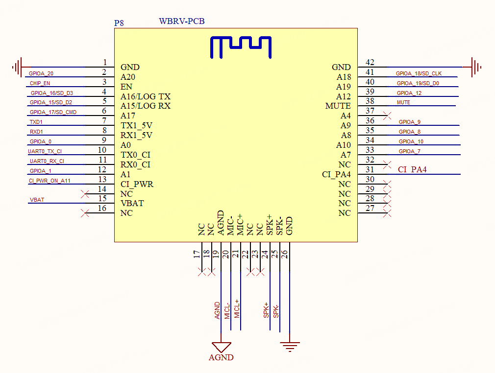
WBRV PCB 封装
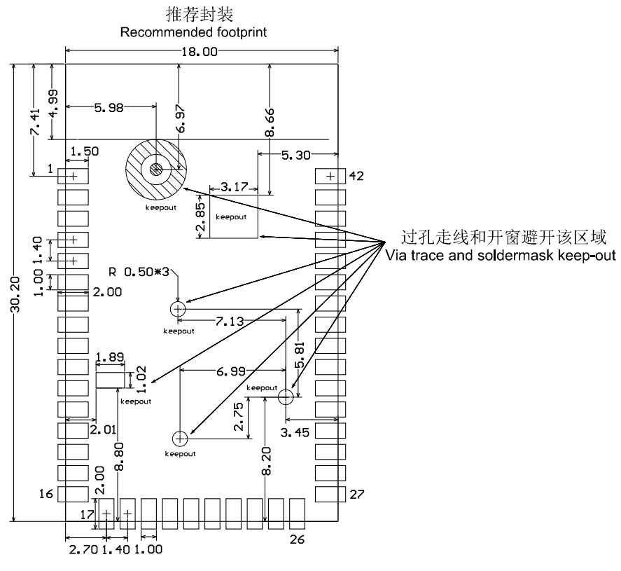
上图中 keep-out 示意区域,不需要上锡,不要走线。
生产指南
-
涂鸦出厂的可贴可插封装模组根据客户底板设计方案选择组装方式,底板设计为贴片封装时使用 SMT 贴片制程进行生产,如果底板设计为插件封装时使用波峰焊制程进行生产。模组产品拆开包装后建议在 24 小时内完成焊接,否则需放置在湿度不超过 10%RH 的干燥柜内,或重新进行真空包装并记录暴露时间,总暴露时间不超过 168 小时。
- (SMT 制程)SMT 贴片所需仪器或设备:
- 贴片机
- SPI
- 回流焊
- 炉温测试仪
- AOI
- (波峰焊制程)波峰焊所需的仪器或设备:
- 波峰焊设备
- 波峰焊接治具
- 恒温烙铁
- 锡条、锡丝、助焊剂
- 炉温测试仪
- 烘烤所需仪器或设备:
- 柜式烘烤箱
- 防静电耐高温托盘
- 防静电耐高温手套
- (SMT 制程)SMT 贴片所需仪器或设备:
-
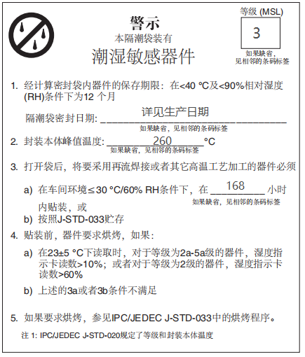
涂鸦出厂的模组存储条件如下:
-
防潮袋必须储存在温度 <40℃、湿度 <90%RH 的环境中。
-
干燥包装的产品,保质期为从包装密封之日起 12 个月的时间。
-
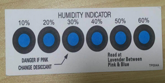
密封包装内装有湿度指示卡:
-
-
涂鸦出厂的模组当出现可能受潮的情况下需要进行烘烤:
- 拆封前发现真空包装袋破损。
- 拆封后发现包装袋内没有湿度指示卡。
- 拆封后如果湿度指示卡读取到 10% 及以上色环变为粉色。
- 拆封后总暴露时间超过 168 小时。
- 从首次密封包装之日起超过 12 个月。
-
烘烤参数如下:
- 烘烤温度:卷盘包装 40℃,小于等于 5% RH。托盘包装 125℃,小于等于 5%RH(耐高温托盘非吸塑盒拖盘)。
- 烘烤时间:卷盘包装 168 小时,托盘包装 12 小时。
- 报警温度设定:卷盘包装 50℃,托盘包装 135℃。
- 自然条件下冷却到 36℃ 以下后,即可进行生产。
- 若烘烤后暴露时间大于 168 小时没有使用完,请再次进行烘烤。
- 如果暴露时间超过 168 小时未经过烘烤,不建议使用波峰焊接工艺焊接此批次模组,因模组为 3 级湿敏器件超过允许的暴露时间很可能受潮,进行高温焊接时可能导致器件失效或焊接不良。
-
在整个生产过程中请对模组进行静电放电(ESD)保护。
-
为了确保产品合格率,建议使用 SPI 和 AOI 测试设备来监控锡膏印刷和贴装品质。
推荐炉温曲线
请根据制程选择相应的焊接方式,SMT 参考回流焊接炉温曲线推荐,波峰焊制程参考波峰焊接炉温曲线推荐。设定炉温与实测炉温有一定差距,本文所示温度均为实测温度。
方式一:SMT 制程(SMT 回流焊接推荐炉温曲线)
请参考回流焊炉温曲线要求进行炉温设定,回流焊温度曲线如下图所示:
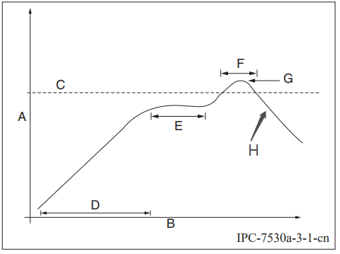
- A:温度轴
- B:时间轴
- C:合金液相线温度区间为 217-220℃
- D:升温斜率为 1-3℃/S
- E:恒温时间为 60-120S,恒温温度区间为 150-200℃
- F:液相线以上时间为 50-70S
- G:峰值温度为 235-245℃
- H:降温斜率为 1-4℃/S
以上推荐曲线以 SAC305 合金焊膏为例。其他合金焊膏请按焊膏规格书推荐炉温曲线设置。
方式二:波峰焊制程(波峰焊接炉温曲线)
请参考波峰焊接炉温建议进行炉温设定,峰值温度 260℃ ± 5℃,波峰焊接温度曲线如下图所示:
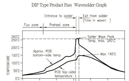
| 波峰焊接炉温曲线建议 | 手工补焊温度建议 | ||
|---|---|---|---|
| 预热温度 | 80-130℃ | 焊接温度 | 360℃ ± 20℃ |
| 预热时间 | 75-100S | 焊接时间 | 小于 3S/点 |
| 波峰接触时间 | 3-5S | NA | NA |
| 锡缸温度 | 260℃ ± 5℃ | NA | NA |
| 升温斜率 | ≤2℃/S | NA | NA |
| 降温斜率 | ≤6℃/S | NA | NA |
储存条件
模组 MOQ 与包装信息
| 产品型号 | MOQ(pcs) | 出货包装方式 | 每个卷盘存放模组数 | 每箱包装卷盘数 |
|---|---|---|---|---|
| WBRV | 4400 | 载带卷盘 | 1100 | 4 |
附录:声明
Important Notice to OEM integrators
-
This module is limited to OEM installation ONLY.
-
This module is limited to installation in mobile or fixed applications, according to Part 2.1091(b).
-
The separate approval is required for all other operating configurations, including portable configurations with respect to Part 2.1093 and different antenna configurations
-
For FCC Part 15.31 (h) and (k): The host manufacturer is responsible for additional testing to verify compliance as a composite system. When testing the host device for compliance with Part
15 Subpart B, the host manufacturer is required to show compliance with Part 15 Subpart B while the transmitter module(s) are installed and operating. The modules should be transmitting and the evaluation should confirm that the module’s intentional emissions are compliant (i.e. fundamental and out of band emissions). The host manufacturer must verify that there are no additional unintentional emissions other than what is permitted in Part 15 Subpart B or emissions are complaint with the transmitter(s) rule(s).
The Grantee will provide guidance to the host manufacturer for Part 15 B requirements if needed.Important Note
Notice that any deviation(s) from the defined parameters of the antenna trace, as described by the instructions, require that the host product manufacturer must notify Tuya that they wish to change the antenna trace design. In this case, a Class II permissive change application is required to be filed by the TUYA, or the host manufacturer can take responsibility through the change in FCC ID (new application) procedure followed by a Class II permissive change application.
End Product Labeling
When the module is installed in the host device, the FCC label must be visible through a window on the final device or it must be visible when an access panel, door or cover is easily re-moved. If not, a second label must be placed on the outside of the final device that contains the following text: "Contains FCC ID: 2ANDL-WBRV".
The FCC ID can be used only when all FCC compliance requirements are met.
Antenna Installation
(1) The antenna must be installed such that 20 cm is maintained between the antenna and users,
(2) The transmitter module may not be co-located with any other transmitter or antenna.
(3) Only antennas of the same type and with equal or less gains as shown below may be used with this module. Other types of antennas and/or higher-gain antennas may require additional authorization for operation.
| Antenna type | BT/Wlan 2.4G |
|---|---|
| PCB | 1.25dBi |
In the event that these conditions cannot be met (for example, certain laptop configurations or co-location with another transmitter), then the FCC authorization is no longer considered valid, and the FCC ID cannot be used on the final product. In these circumstances, the OEM integrator will be responsible for re-evaluating the end product (including the transmitter) and obtaining a separate FCC authorization.
Manual Information to the End User
The OEM integrator has to be aware not to provide information to the end user regarding how to install or remove this RF module in the user’s manual of the end product which integrates this module. The end user manual shall include all required regulatory information/warnings as shown in this manual.
Federal Communication Commission Interference Statement
This device complies with Part 15 of the FCC Rules. Operation is subject to the following two conditions: (1) This device may not cause harmful interference, and (2) this device must accept any interference received, including interference that may cause undesired operation.
This equipment has been tested and found to comply with the limits for a Class B digital device, pursuant to Part 15 of the FCC Rules. These limits are designed to provide reasonable protection against harmful interference in a residential installation. This equipment generates, uses, and can radiate radio frequency energy and, if not installed and used in accordance with the instructions, may cause harmful interference to radio communications. However, there is no guarantee that interference will not occur in a particular installation. If this equipment does cause harmful interference to radio or television reception, which can be determined by turning the equipment off and on, the user is encouraged to try to correct the interference by one of the following measures:
- Reorient or relocate the receiving antenna.
- Increase the separation between the equipment and receiver.
- Connect the equipment into an outlet on a circuit different from that to which the receiver is connected.
- Consult the dealer or an experienced radio/TV technician for help.
Any changes or modifications not expressly approved by the party responsible for compliance could void the user’s authority to operate this equipment. This transmitter must not be co-located or operating in conjunction with any other antenna or transmitter.
List of applicable FCC rules
This module has been tested and found to comply with Part 15 requirements for Modular Approval.
The modular transmitter is only FCC authorized for the specific rule parts (i.e., FCC transmitter rules) listed on the grant, and that the host product manufacturer is responsible for compliance with any other FCC rules that apply to the host not covered by the modular transmitter grant of certification. If the grantee markets their product as being Part 15 Subpart B compliant (when it also contains unintentional-radiator digital circuitry), then the grantee shall provide a notice stating that the final host product still requires Part 15 Subpart B compliance testing with the modular transmitter installed.
This device is intended only for OEM integrators under the following conditions: (For module device use)
- The antenna must be installed such that 20 cm is maintained between the antenna and users, and
- The transmitter module may not be co-located with any other transmitter or antenna.
As long as 2 conditions above are met, further transmitter tests will not be required. However, the OEM integrator is still responsible for testing their end-product for any additional compliance requirements required with this module installed.
Radiation Exposure Statement
This equipment complies with FCC radiation exposure limits set forth for an uncontrolled environment. This equipment should be installed and operated with a minimum distance of 20 cm between the radiator & your body.
该内容对您有帮助吗?
是意见反馈该内容对您有帮助吗?
是意见反馈