Prototype a Robotic Lawn Mower

Overview
Getting your lawn spruced up in the summer sun is often a dreaded chore for homeowners. A robotic lawn mower can eliminate one of the most daunting summer chores. It looks similar to a robot vacuum. You can just watch it darting around your lawn and keeping your lawn in tip-top shape. Equipping a mower with IoT-enabled features like Bluetooth or Wi-Fi connectivity, GPS navigation, and flexible scheduling capabilities can let you control the mower and track mowing progress using a mobile app from anywhere.
Features
- Powered by a lithium battery, the mower is super quiet and can send low-battery alerts.
- Measure the mowing path.
- Adjust the cutting height.
- Automatic route planning.
- Remote control by using the mobile app.
Materials
Network module
Count:1Tuya's Wi-Fi module or Wi-Fi and Bluetooth LE combo module.
Battery
Count:112V lithium battery
Buck converter
Count:1LM2596 from Texas Instruments
Geared motor
Count:4MG513 DC 12V geared motor
Motor driver
Count:1TB6612FNG motor driver from Toshiba
Motor
Count:1900 Kv brushless DC electric motor
Electronic speed controller (ESC)
Count:1Servo
Count:2Global navigation satellite system (GNSS)
Count:1Tuya's GUC300 GNSS module
Electronic compass sensor
Count:1
Steps
Step 1: Hardware design
The mower includes four hardware parts.
- Wireless connectivity system: Tuya’s network modules allow remote control and viewing mower status on the mobile app from anywhere.
- Power system: 12V lithium battery pack coupled with geared motor pushes rubber tire wheels forward.
- Mowing control system: Two servos enable adjustment of cutting heights, and brushless DC motors are used for the cutting blades and drive wheels.
- Positioning and navigation system: Incorporate a GNSS module and magnetic sensor to achieve navigation and positioning capability.
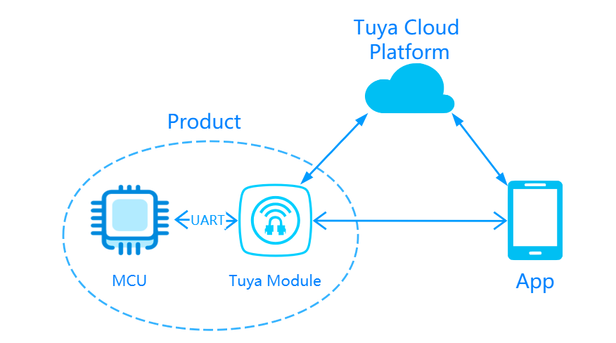
Wireless connectivity system
Interface your MCU with Tuya’s network modules and make your product IoT-enabled and connected to the cloud.
Tuya provides one-stop IoT development services including the three essentials for typical IoT products, namely network modules, mobile apps, and cloud services. With Tuya’s MCU SDK, all-in-one mobile apps, and control panels, you can focus on application development simply, connect your product to the Tuya IoT Platform easily, and benefit from the cloud services quickly.
The MCU SDK is automatically generated based on the product features you defined on the Tuya IoT Platform. To facilitate interfacing with the protocol, the MCU SDK has built-in support for communication and protocol parsing. You can add this SDK to existing projects and complete the required configuration to implement the MCU program development.
Hardware resource requirements
SDK requirements for the MCU are as follows. If your MCU does not have sufficient resources, you can refer to the functions in the SDK for interfacing with Tuya’s protocol.
- Memory: 4 KB
- RAM: About 100 bytes of the RAM are required, depending on the data length of the data point (DP). If you enable OTA updates, it must be greater than 260 bytes.
- Nested function: 9-level.
Select a network module
Tuya provides a bunch of modules with different protocols for various demands on the IoT projects, such as the Wi-Fi module and the Wi-Fi and Bluetooth LE module.
To streamline the development process, you can opt for Tuya Sandwich Evaluation Kit.
Power system
Power supply
Typically, mowers on the market are powered by either gas or battery.
A gas mower can go the distance as long as it has enough fuel and be more powerful than the battery-powered mower. However, it makes more noise than the battery option and creates emissions throughout the gas combustion process.
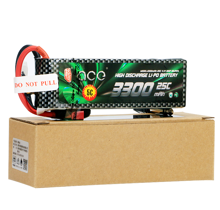
We choose the eco-friendly lithium battery pack to power our mower to mitigate the noise and pollution impacts.
Battery
3S or 4S 12V lithium-ion battery is recommended. The charge and discharge rates of a lithium-ion battery can be 15C or even over 20C, which ensures powerful forces to push wheels forward. If you do not opt for the lithium-ion battery, choose batteries with long service life and a maximum output current of more than 5A.
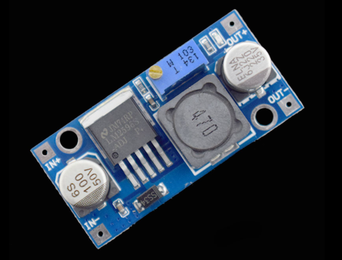
Buck converter
We need a buck converter to provide output voltages for different systems.
The buck converter LM2596 is available in fixed output voltages of 3.3V, 5V, 12V, and an adjustable output version. It has the following features.
- Input voltage range up to 40 V.
- Adjustable version output voltage range: 1.2V to 37V ±4% maximum over the line and load conditions.
- 3A output load current.
- High efficiency.
- Thermal shutdown and current-limit protection.
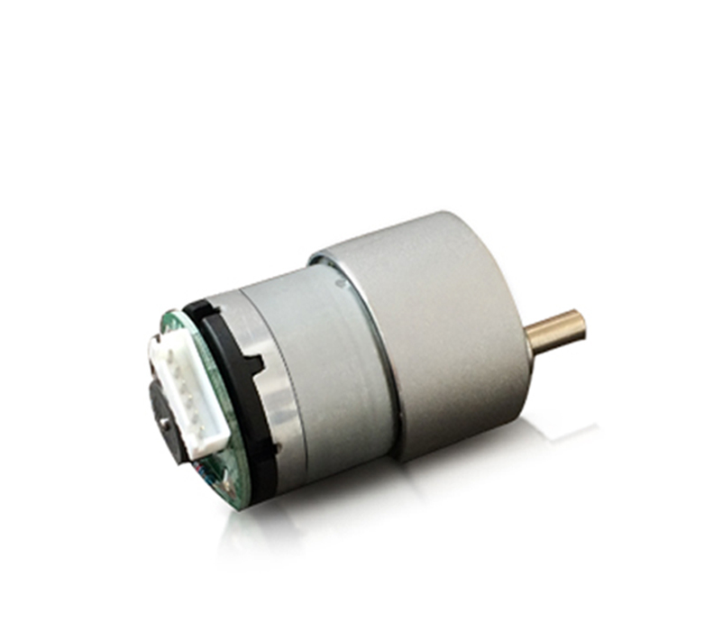
Geared motor
The geared motor can be defined as an extension of the DC motor. It has a gear assembly attached to the motor to increase the torque and reduce the speed.
The rated voltage of the geared motor must match that of the battery. The supply voltage of a 12V motor ranges from 11V to 16V.
We choose the MG513 DC 12V geared motor with a rated output current of 0.36A. Its reduction ratio is 1/60, and its no-load speed is 183 RPM. The motor can provide a torque of 2 kgf.cm and a maximum load of 6 kg. With 65 mm rubber wheels, the mower can reach a speed of 0.5 m/s.
The motor has a built-in Hall effect sensor. Based on magnetic induction, we can get the rotation speed of the motor and then measure the speed and distance covered.
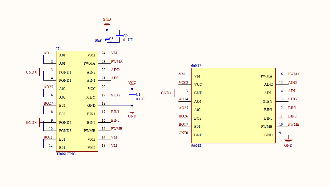
Motor driver
Toshiba’s TB6612FNG driver is a MOSFET-based dual-channel H-bridge integrated circuit. It has the following features.
- Power supply voltage: VM = 15V (Max).
- Output current: I = 1.2A (ave)/3.2A (peak).
- Output low ON resistor: 0.5Ω.
- Built-in thermal shutdown circuit and low voltage detecting circuit.
- Switching frequency of PWM signal: 100 kHz.
TB6612FNG does not need a heat sink because it is much more efficient than the bipolar junction transistors (BJT) based drivers such as the L298N. It has a simple peripheral circuit, so adding a power supply filter capacitor can drive the motor.
The TB6612FNG has a pair of drivers and can control two motors independently. Therefore, we only need two TB6612FNG ICs for four motors.
When
STBYpin is high, the two input signals,IN1andIN2, can be one of four modes such as clockwise (CW), counterclockwise (CCW), short brake, and stop mode.AIN1 AIN2 Mode 0 1 CCW 1 0 CW 1 1 Short brake 0 0 Stop The schematic diagram is as follows.
Mowing control system
The mowing control system enables adjustment of cutting height and controls the mowing operation.
Brushless DC motor
The brushless motor does not have brushes so there is no electric spark generated when the brush motor is running, which greatly reduces the interference of the electric spark to the remote control over radio frequency (RF) devices. Without brushes, the friction is greatly reduced during operation, the operation is smooth, and the noise is much lower. This advantage is a huge support for the stability and long service life.
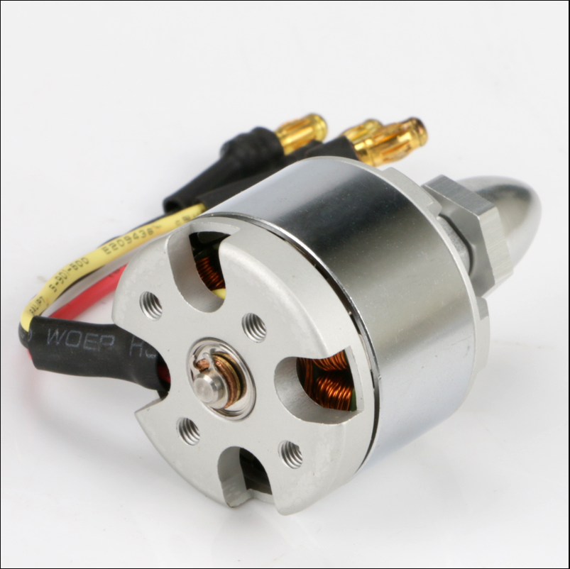
We use the brushless motor with 900 Kv. When you choose a motor, consider two factors of Kv rating and torque. The Kv rating of a brushless motor is the ratio of the motor’s unloaded RPM to the peak voltage on the wires connected to the coils. Generally speaking, the more Kv a motor has, the less torque the motor can produce.
Regarding the dimension, 2212 motor is recommended.
Electronic speed controller (ESC)
An electronic speed controller (ESC) is an electronic circuit that controls and regulates the speed of an electric motor.
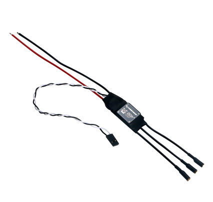
We use a 20A ESC. Make sure the output current of your ESC matches that of your brushless motor.
It has the following features.
- A special core program for multi-rotor controllers greatly improves throttle response.
- Specially optimized software for excellent compatibility with disc-type motors.
- All settings except the timing are preset, making usage simple, highly intelligent, and adaptive.
- The twisted-pair design of the throttle signal cable effectively reduces the crosstalk produced in signal transmission and makes flight more stable.
- A special drive chip has a much better MOSFET driving effect than a common driving circuit consisted of discrete components.
- MOSFET with extra-low resistance brings high performance and great current endurance.
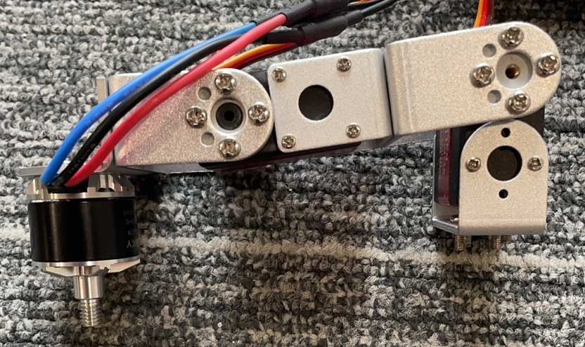
Servo
A servo contains the DC motor, control circuit, reducer, feedback mechanism, and other circuits. It can go to a specific position depending on the input signal. Its internal potentiometer or angle sensor can sense the position of the output shaft so that the control board can accurately control the rotation of the output shaft accordingly.
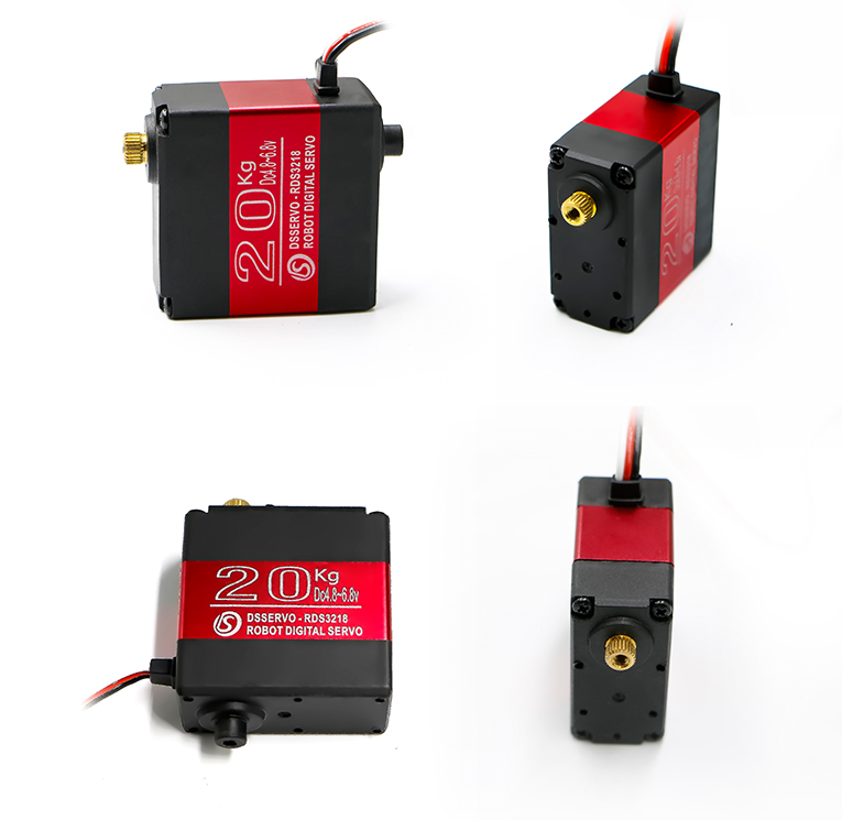
Typically, a servo has three wires: the brown or black one is the ground wire, the red one is the power wire, and the orange or white one is the signal wire.
The servo can work with 4V to 6V, and 5V is the recommended voltage. The angle of servo rotation is achieved by adjusting the duty cycle of the PWM signal. The period of the standard PWM signal is fixed at 20 ms (50 Hz). The pulse width is between 0.5 ms and 2.5 ms, corresponding to the servo rotation angle of 0° to 180°.
Two servos and some metal discs make up a lift structure to adjust the cutting height.
Positioning and navigation system
Positioning and navigation system enables positioning and orienteering.
GNSS positioning
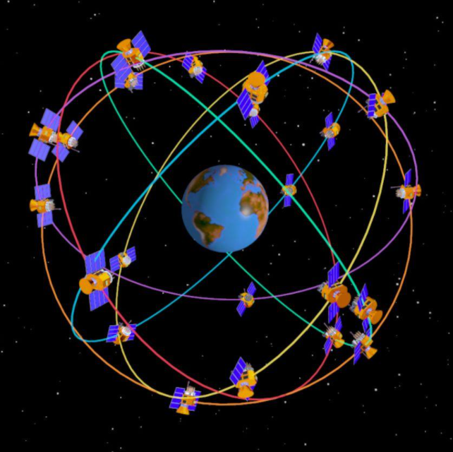
A global navigation satellite system (GNSS) is a network of satellites broadcasting timing and orbital information used for navigation and positioning measurements. Currently, the United States’ Global Positioning System (GPS), Russia’s Global Navigation Satellite System (GLONASS), China’s BeiDou Navigation Satellite System (BDS), and the European Union’s Galileo are fully operational GNSSs.
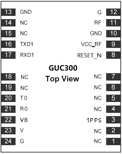
We use Tuya’s GUC300 GNSS module for positioning and navigation purposes.
GUC300 consists of a highly integrated GNSS chip UFirebird-UC6226NIS and peripheral circuits. It has the built-in SAW filter, low noise amplifier (LNA), 26 MHz temperature compensated crystal oscillator (TCXO), and other components. It supports both GPS and BDS satellite navigation systems.
GUC300 has the following features.
-
Positioning engine:
- 64 simultaneous tracking channels
- Hot start time: < 1.2 seconds
- Cold start sensitivity: -145 dBm. Tracking sensitivity: -158 dBm
- Data update rate: up to 10 Hz
-
Support for both GPS and BDS
- RF subsystem adopts a broadband design. The input signal is centered at about 1575 MHz.
- Receiving and tracking GPS’s 1575.42 MHz L1 signal
- Receiving and tracking the BDS satellite navigation system’s 1561.098 MHz B1 signal
- GUC300 defaults to receiving GPS and BDS signals and can be customized as GPS+BDS, GPS+GLONASS, or a single GNSS system. You can file a service ticket to request the required GNSS firmware.
GUC300 outputs
$GNRMC,$GNGGA, and$GPGSVsentences every one second by default. The serial baud rate is 9600. We can parse$GNGGAsentences.$GNGGA,071520.00,3018.12971,N,12003.84423,E,1,20,1.47,60.5,M,,M,,\*61The fields of the above sentences are described as follows.
$GNGGA,<1>,<2>,<3>,<4>,<5>,<6>,<7>,<8>,<9>,M,<10>,M,<11>,<12>*xx<CR><LF>\$GNGGA: Sentence type identifier. This example indicates the GGA protocol header.- <1>: UTC time, the format is
hhmmss.sss. - <2>: Latitude, the format is
ddmm.mmmm. Leading zeros are inserted. - <3>: Latitude hemisphere, N or S (north latitude or south latitude).
- <4>: Longitude, the format is
dddmm.mmmm. Leading zeros are inserted. - <5>: Longitude hemisphere, E or W (east longitude or west longitude).
- <6>: GPS positioning status.
0: initializing.1: single point positioning.2: differential.3: invalid PPS.4: fixed solution.5: floating point solution.6: estimating.7: fixed value of manual input.8: simulation mode.9: WAAS differential. - <7>: Number of satellites used, ranging from 00 to 12. Leading zeros are inserted.
- <8>: Horizontal dilution of precision (HDOP), ranging from 0.5 to 99.9. The smaller the HDOP, the better the satellite distribution.
- <9>: Sea level altitude, ranging from -9999.9 to 9999.9.
- In a unit of meter.
- <10>: The height of the earth ellipsoid relative to the geoid, ranging from -9999.9 to 9999.9.
- In a unit of meter.
- <11>: The number of seconds since the last time the differential GPS signal was received. If differential positioning is not adopted, this field will be empty.
- <12>: Differential reference base station label, ranging from 0000 to 1023. Leading zeros are inserted.
- xx: XOR check value of all ASCII characters starting from
$to\*. - <CR>: carriage return, end tag.
- <LF>: line feed, end tag.
Circuit diagram
Electronic compass sensor
We choose a 3-axis electronic compass sensor QMC5883L.
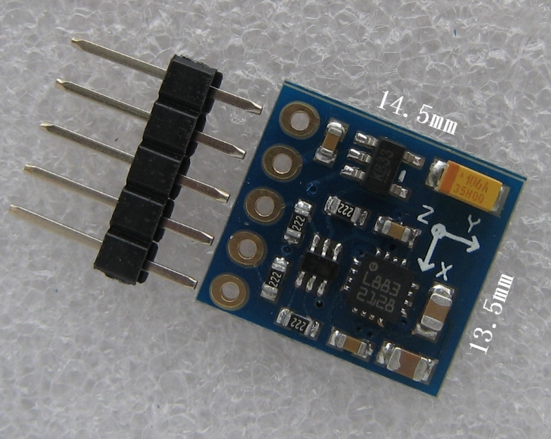
The electronic compass consists of a 3D magnetoresistive sensor, a 2-axis inclinometer, and an MCU. The 3D magnetoresistive sensor is used to monitor changes in the geomagnetic field, and the inclinometer can measure angles between the sensing directions and the ground plane (relative to gravity). The MCU processes the input signals and outputs data for compensating for hard- and soft-iron distortion. The magnetometer comprises three magnetoresistive sensors in x-, y-, and z-direction to measure the geomagnetic field strength accordingly. The sensitivity of the sensor in each direction has been optimally calibrated according to the vector of the geomagnetic field. The cross-axis sensitivity has been minimized. The analog output signal from the sensor will be amplified and then sent to the MCU for processing.
We can use the following formula to calculate the direction.
direction.x=atan2((double)Mag_data.y,(double)Mag_data.x)*57.3+180;
Mag_data.xandMag_data.yare the data from the X-axis and Y-axis respectively.atan2is the angle in radians between the positive x-axis of a plane and the point given by the coordinates (x, y) on it. Multiply the radian value by 57.3 to convert radians to degrees. Finally, add 180 degrees to the converted value.For the calculation result, true south is 0 or 360, west is 90, north is 180, east is 270.
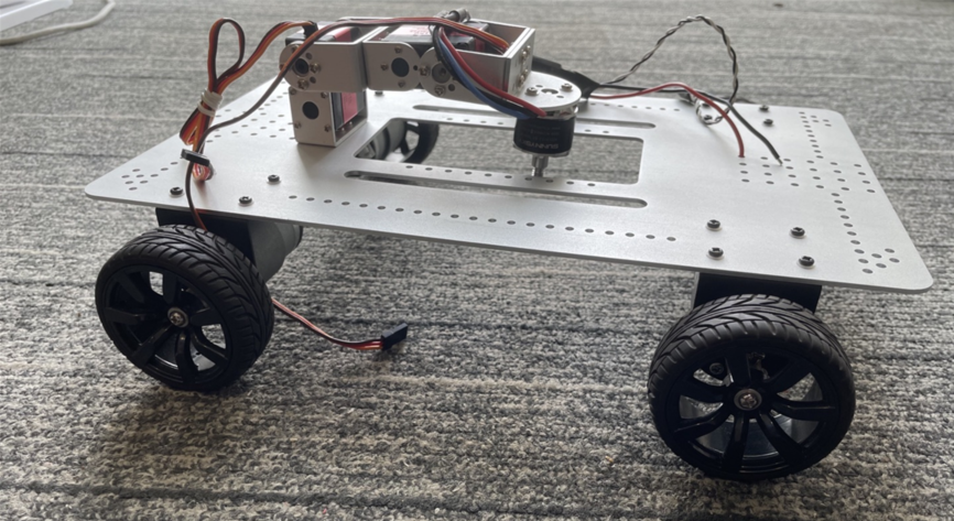
Assemble the device
Design a base plate on which the wheels, servos, and other components are mounted. Download the base plate structure file.
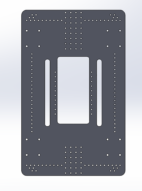
The entire assembly looks like this.
We need to design a PCB layout to place the components such as the motor driver and power supply. Make sure to reserve space for interfaces for servos, motors, and electronic compass to keep the project neat. You can also add some features such as a buzzer for alarming and LEDs for signaling.
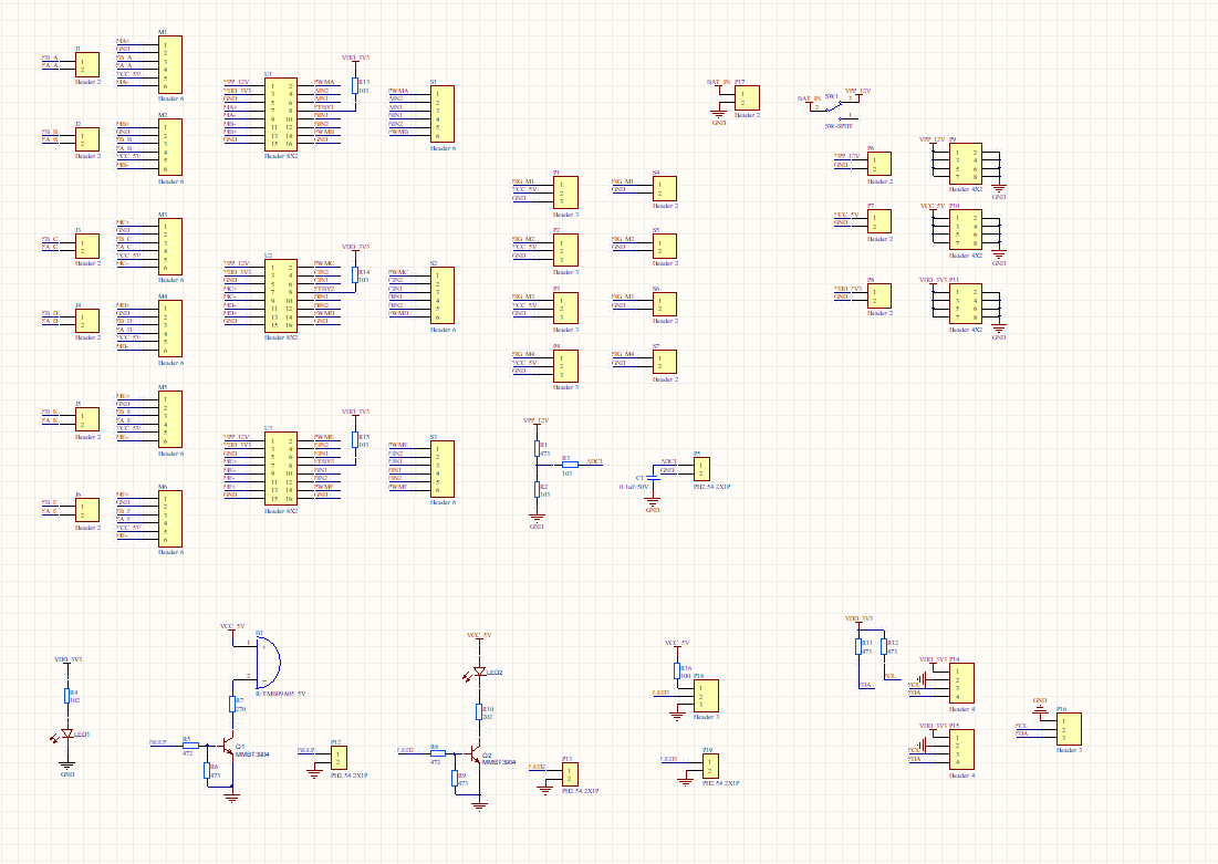
Circuit diagram
Finally, mount the GPS, microcontroller, and power supply unit on the PCB, and the PCB assembly is completed.
Step 2: Create product
-
Log in to the Tuya IoT Platform.
-
Click Create.

-
Scroll down the page and click Can’t find the category? in the lower-left corner.
-
Complete the required information and click Create.
- Product Name, Product Description, and Product Model are user-defined.
- Select Wi-Fi-Bluetooth as the protocol, and click Create.

-
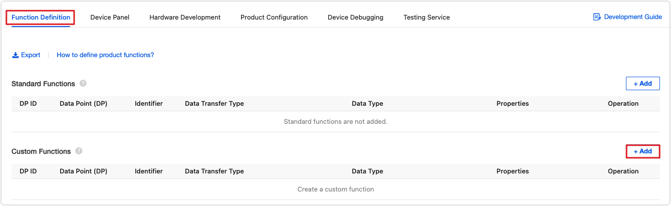
In the Custom Functions section, click Add to create required functions. In the step of Function Definition, you can add standard functions or create custom functions as needed.
We set up the following functions.
- Standard function: direction control
- Custom function: blade position, blade rotation speed, cutting length, cutting width, and zigzag mowing mode.
-
In the second step of the Device Panel tab, select the desired panel. In the second step of Device Panel, you can select the debugging-friendly DIY Style Panel.
-
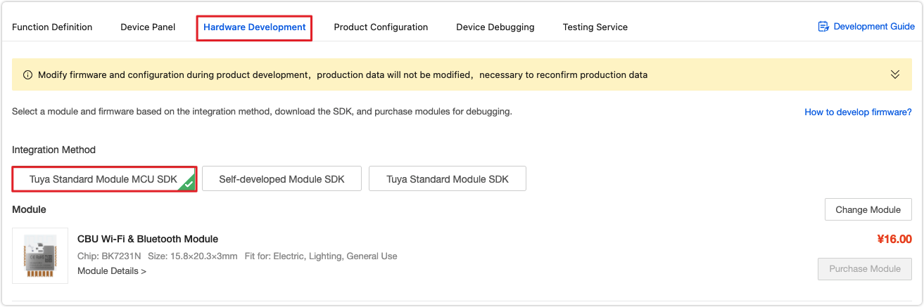
In the third step of Hardware Development, select Tuya Standard Module SDK.
-
Scroll down the page and find Download Documents. Click Download All to download all the files needed for MCU SDK development.

The operation on the platform is completed. You can try the remote control with the virtual device using the Tuya Smart app.

-
Step 3: Firmware development
Before the application development, you need to port the MCU SDK to your project.
Then, flash the general firmware and Tuya’s license to the network module. This way, the mower can communicate with the cloud.
The demo routine also includes FreeRTOS to facilitate your development.
After the above preparation is completed, you can proceed with the application development.
Download the sample code: tuya-iotos-embeded-mcu-demo-wifi-ble-samrt-lawn-mower
Drivers for motor, servo, and ESC
Have four motors connected to each wheel for movement. Two servos are used to control the ESC as well as the position of the blade connected to the ESC. The ESC controls and regulates the speed of the blade rotation.
Write the initialization procedure for the above components, which are implemented in
servo_motor.c.- Define macros for output GPIOs.
#define MOTOR_PORT_1 GPIOA #define MOTOR_PIN_1 GPIO_PIN_15 #define MOTOR_PORT_1_P GPIOD #define MOTOR_PIN_1_P GPIO_PIN_0 #define MOTOR_PORT_1_N GPIOD #define MOTOR_PIN_1_N GPIO_PIN_7 #define MOTOR_PORT_2 GPIOB #define MOTOR_PIN_2 GPIO_PIN_9 #define MOTOR_PORT_2_P GPIOD #define MOTOR_PIN_2_P GPIO_PIN_1 #define MOTOR_PORT_2_N GPIOD #define MOTOR_PIN_2_N GPIO_PIN_2 #define MOTOR_PORT_3 GPIOB #define MOTOR_PIN_3 GPIO_PIN_10 #define MOTOR_PORT_3_P GPIOD #define MOTOR_PIN_3_P GPIO_PIN_3 #define MOTOR_PORT_3_N GPIOD #define MOTOR_PIN_3_N GPIO_PIN_4 #define MOTOR_PORT_4 GPIOB #define MOTOR_PIN_4 GPIO_PIN_11 #define MOTOR_PORT_4_P GPIOD #define MOTOR_PIN_4_P GPIO_PIN_8 #define MOTOR_PORT_4_N GPIOD #define MOTOR_PIN_4_N GPIO_PIN_9 #define MOTOR_CHANNEL_1 TIMER_CH_0 #define MOTOR_CHANNEL_2 TIMER_CH_1 #define MOTOR_CHANNEL_3 TIMER_CH_2 #define MOTOR_CHANNEL_4 TIMER_CH_3 #define SERVO_PORT_1 GPIOC #define SERVO_PIN_1 GPIO_PIN_6 #define SERVO_PORT_2 GPIOC #define SERVO_PIN_2 GPIO_PIN_7 #define BLADE_MOTOR_PORT GPIOC #define BLADE_MOTOR_PIN GPIO_PIN_8- Call the initialization interface to turn on the GPIO clock and specify the output GPIO as the normal mode or PWM mode. Then, call
timer_configto set the PWM parameters.
void servo_motor_init(void) { rcu_periph_clock_enable(RCU_GPIOA); rcu_periph_clock_enable(RCU_GPIOB); rcu_periph_clock_enable(RCU_GPIOC); rcu_periph_clock_enable(RCU_GPIOD); /*Configure PD1~8 Output motor Positive and Negative pin to drive wheels_1~4*/ gpio_mode_set(GPIOD, GPIO_MODE_OUTPUT, GPIO_PUPD_NONE, MOTOR_PIN_1_P | MOTOR_PIN_1_N | MOTOR_PIN_2_P | MOTOR_PIN_2_N | MOTOR_PIN_3_P | MOTOR_PIN_3_N | MOTOR_PIN_4_P | MOTOR_PIN_4_N); gpio_output_options_set(GPIOD, GPIO_OTYPE_PP, GPIO_OSPEED_50MHZ,MOTOR_PIN_1_P | MOTOR_PIN_1_N | MOTOR_PIN_2_P | MOTOR_PIN_2_N | MOTOR_PIN_3_P | MOTOR_PIN_3_N | MOTOR_PIN_4_P | MOTOR_PIN_4_N); gpio_bit_reset(GPIOD, MOTOR_PIN_1_P | MOTOR_PIN_1_N | MOTOR_PIN_2_P | MOTOR_PIN_2_N | MOTOR_PIN_3_P | MOTOR_PIN_3_N | MOTOR_PIN_4_P | MOTOR_PIN_4_N); /*Configure PA15(TIMER1_CH0) Output PWM pulse to drive wheels_1*/ gpio_mode_set(MOTOR_PORT_1, GPIO_MODE_AF, GPIO_PUPD_NONE, MOTOR_PIN_1); gpio_output_options_set(MOTOR_PORT_1, GPIO_OTYPE_PP, GPIO_OSPEED_50MHZ,MOTOR_PIN_1); gpio_af_set(MOTOR_PORT_1, GPIO_AF_1, MOTOR_PIN_1); /*Configure PB9(TIMER1_CH1) Output PWM pulse to drive wheels_2*/ gpio_mode_set(MOTOR_PORT_2, GPIO_MODE_AF, GPIO_PUPD_NONE, MOTOR_PIN_2); gpio_output_options_set(MOTOR_PORT_2, GPIO_OTYPE_PP, GPIO_OSPEED_50MHZ,MOTOR_PIN_2); gpio_af_set(MOTOR_PORT_2, GPIO_AF_1, MOTOR_PIN_2); /*Configure PB10(TIMER1_CH2) Output PWM pulse to drive wheels_3*/ gpio_mode_set(MOTOR_PORT_3, GPIO_MODE_AF, GPIO_PUPD_NONE, MOTOR_PIN_3); gpio_output_options_set(MOTOR_PORT_3, GPIO_OTYPE_PP, GPIO_OSPEED_50MHZ,MOTOR_PIN_3); gpio_af_set(MOTOR_PORT_3, GPIO_AF_1, MOTOR_PIN_3); /*Configure PB11(TIMER1_CH3) Output PWM pulse to drive wheels_4*/ gpio_mode_set(MOTOR_PORT_4, GPIO_MODE_AF, GPIO_PUPD_NONE, MOTOR_PIN_4); gpio_output_options_set(MOTOR_PORT_4, GPIO_OTYPE_PP, GPIO_OSPEED_50MHZ,MOTOR_PIN_4); gpio_af_set(MOTOR_PORT_4, GPIO_AF_1, MOTOR_PIN_4); /*Configure PC6(TIMER2_CH0) Output PWM pulse to drive servo no.1*/ gpio_mode_set(SERVO_PORT_1, GPIO_MODE_AF, GPIO_PUPD_NONE, SERVO_PIN_1); gpio_output_options_set(SERVO_PORT_1, GPIO_OTYPE_PP, GPIO_OSPEED_50MHZ,SERVO_PIN_1); gpio_af_set(SERVO_PORT_1, GPIO_AF_2, SERVO_PIN_1); /*Configure PC7(TIMER2_CH1) Output PWM pulse to drive servo no.2*/ gpio_mode_set(SERVO_PORT_2, GPIO_MODE_AF, GPIO_PUPD_NONE, SERVO_PIN_2); gpio_output_options_set(SERVO_PORT_2, GPIO_OTYPE_PP, GPIO_OSPEED_50MHZ,SERVO_PIN_2); gpio_af_set(SERVO_PORT_2, GPIO_AF_2, SERVO_PIN_2); /*Configure PC8(TIMER2_CH2) Output PWM pulse to drive blade motor*/ gpio_mode_set(BLADE_MOTOR_PORT, GPIO_MODE_AF, GPIO_PUPD_NONE, BLADE_MOTOR_PIN); gpio_output_options_set(BLADE_MOTOR_PORT, GPIO_OTYPE_PP, GPIO_OSPEED_50MHZ,BLADE_MOTOR_PIN); gpio_af_set(BLADE_MOTOR_PORT, GPIO_AF_2, BLADE_MOTOR_PIN); timer_config(); } void timer_config(void) { uint16_t i = 0; /* TIMER1 configuration: generate PWM signals with different duty cycles: TIMER1CLK = SystemCoreClock / 120 = 1MHz */ timer_oc_parameter_struct timer_ocintpara; timer_parameter_struct timer_initpara; rcu_periph_clock_enable(RCU_TIMER1); rcu_periph_clock_enable(RCU_TIMER2); rcu_timer_clock_prescaler_config(RCU_TIMER_PSC_MUL4); timer_struct_para_init(&timer_initpara); timer_deinit(TIMER1); timer_deinit(TIMER2); /* TIMER1 configuration */ timer_initpara.prescaler = 119; timer_initpara.alignedmode = TIMER_COUNTER_EDGE; timer_initpara.counterdirection = TIMER_COUNTER_UP; timer_initpara.period = 500; /* 500*(1/1MHZ) = 500us */ timer_initpara.clockdivision = TIMER_CKDIV_DIV1; timer_initpara.repetitioncounter = 0; timer_init(TIMER1,&timer_initpara); /* TIMER2 configuration */ timer_initpara.prescaler = 119; timer_initpara.alignedmode = TIMER_COUNTER_EDGE; timer_initpara.counterdirection = TIMER_COUNTER_UP; timer_initpara.period = 20000; /* 20000*(1/1MHZ) = 20ms */ timer_initpara.clockdivision = TIMER_CKDIV_DIV1; timer_initpara.repetitioncounter = 0; timer_init(TIMER2,&timer_initpara); timer_channel_output_struct_para_init(&timer_ocintpara); timer_ocintpara.ocpolarity = TIMER_OC_POLARITY_HIGH; timer_ocintpara.outputstate = TIMER_CCX_ENABLE; timer_ocintpara.ocnpolarity = TIMER_OCN_POLARITY_HIGH; timer_ocintpara.outputnstate = TIMER_CCXN_DISABLE; timer_ocintpara.ocidlestate = TIMER_OC_IDLE_STATE_LOW; timer_ocintpara.ocnidlestate = TIMER_OCN_IDLE_STATE_LOW; for(i = 0; i < 4; i++) { timer_channel_output_config(TIMER1,i,&timer_ocintpara); timer_channel_output_pulse_value_config(TIMER1,i,0); timer_channel_output_mode_config(TIMER1,i,TIMER_OC_MODE_PWM0); timer_channel_output_shadow_config(TIMER1,i,TIMER_OC_SHADOW_DISABLE); } for(i = 0; i < 3; i++) { timer_channel_output_config(TIMER2,i,&timer_ocintpara); timer_channel_output_pulse_value_config(TIMER2,i,0); timer_channel_output_mode_config(TIMER2,i,TIMER_OC_MODE_PWM0); timer_channel_output_shadow_config(TIMER2,i,TIMER_OC_SHADOW_DISABLE); } /* auto-reload preload enable */ timer_auto_reload_shadow_enable(TIMER1); timer_auto_reload_shadow_enable(TIMER2); /* TIMER enable */ timer_enable(TIMER1); timer_enable(TIMER2); }- Adjust the PWM duty cycle for motors and servos and encapsulate the operation of duty cycle adjustment as a general interface. Take the motor connected to the wheels as an example.
car_movingis used to adjust the positive and negative level and duty cycle according to the input direction and speed, and therefore to control the wheels.
void car_moving(MOVING_DIRECTION direction, uint16_t speed_value)
{
    uint8_t i;
    switch(direction) {

	case forward:

	    gpio_bit_set(GPIOD, MOTOR_PIN_1_P | MOTOR_PIN_2_P | MOTOR_PIN_3_P | MOTOR_PIN_4_P);
		gpio_bit_reset(GPIOD, MOTOR_PIN_1_N | MOTOR_PIN_2_N | MOTOR_PIN_3_N | MOTOR_PIN_4_N);

		for(i = 0; i < 4; i++) {
		    timer_channel_output_pulse_value_config(TIMER1,i,speed_value);
        }
		break;
	case right:

	    gpio_bit_set(GPIOD, MOTOR_PIN_1_P | MOTOR_PIN_2_P | MOTOR_PIN_3_P | MOTOR_PIN_4_P);
		gpio_bit_reset(GPIOD, MOTOR_PIN_1_N | MOTOR_PIN_2_N | MOTOR_PIN_3_N | MOTOR_PIN_4_N);

		//Since the two sets of wheels on the right are always faster than the left in the actual commissioning process, 60 is added to compensate
		timer_channel_output_pulse_value_config(TIMER1,MOTOR_CHANNEL_1,speed_value + 60);
		timer_channel_output_pulse_value_config(TIMER1,MOTOR_CHANNEL_3,speed_value + 60);

		timer_channel_output_pulse_value_config(TIMER1,MOTOR_CHANNEL_2,speed_value);
		timer_channel_output_pulse_value_config(TIMER1,MOTOR_CHANNEL_4,speed_value);
		break;
	case left:

	    gpio_bit_set(GPIOD, MOTOR_PIN_1_P | MOTOR_PIN_2_P | MOTOR_PIN_3_P | MOTOR_PIN_4_P);
		gpio_bit_reset(GPIOD, MOTOR_PIN_1_N | MOTOR_PIN_2_N | MOTOR_PIN_3_N | MOTOR_PIN_4_N);

		timer_channel_output_pulse_value_config(TIMER1,MOTOR_CHANNEL_1,speed_value);
		timer_channel_output_pulse_value_config(TIMER1,MOTOR_CHANNEL_3,speed_value);

        timer_channel_output_pulse_value_config(TIMER1,MOTOR_CHANNEL_2,speed_value + 50);
		timer_channel_output_pulse_value_config(TIMER1,MOTOR_CHANNEL_4,speed_value + 50);
		break;
	case backward:

	    gpio_bit_reset(GPIOD, MOTOR_PIN_1_P | MOTOR_PIN_2_P | MOTOR_PIN_3_P | MOTOR_PIN_4_P);
		gpio_bit_set(GPIOD, MOTOR_PIN_1_N | MOTOR_PIN_2_N | MOTOR_PIN_3_N | MOTOR_PIN_4_N);

		for(i = 0; i < 4; i++) {
		    timer_channel_output_pulse_value_config(TIMER1,i,speed_value);
        }
		break;
	case stop:

	    gpio_bit_reset(GPIOD, MOTOR_PIN_1_P | MOTOR_PIN_2_P | MOTOR_PIN_3_P | MOTOR_PIN_4_P);
		gpio_bit_reset(GPIOD, MOTOR_PIN_1_N | MOTOR_PIN_2_N | MOTOR_PIN_3_N | MOTOR_PIN_4_N);

	    for(i = 0; i < 4; i++) {
		    timer_channel_output_pulse_value_config(TIMER1,i,speed_value);
        }
	    break;
	default:
				break;
		}
}
Proportional-integral-derivative (PID) algorithm for linear movement correction
Since the four wheels are controlled by independent motors, errors and other factors can cause the mower to deviate from a linear movement even if PWM outputs are set to the same duty cycle. Therefore, we use the PID algorithm to dynamically adjust the actual rotation speed of each wheel.
The linear movement indicates that the four wheels move the same distance simultaneously. Because the four wheels have an identical diameter, the rotation speed of each wheel should be the same. Because the motor speed directly determines the pulses output from the motor’s encoder, we use the number of pulses output from the motor’s encoder per unit time in real time as the input to the PID algorithm and the duty cycle increment as the controlled object. We can keep fine tuning the pulse to enable the four motors to reach the same value.- Collect the increments per unit time of pulses output from the motor’s encoder by counting pulses through an external interrupt. The
movement_system_init()function inmovement.cincludes the configuration of the external interrupt.
void movement_system_init(void) { rcu_periph_clock_enable(RCU_SYSCFG); gpio_mode_set(GPIOC, GPIO_MODE_INPUT, GPIO_PUPD_NONE, GPIO_PIN_0); nvic_irq_enable(EXTI0_IRQn, 2U, 0U); syscfg_exti_line_config(EXTI_SOURCE_GPIOC, EXTI_SOURCE_PIN0); exti_init(EXTI_0, EXTI_INTERRUPT, EXTI_TRIG_RISING); exti_interrupt_flag_clear(EXTI_0); gpio_mode_set(GPIOC, GPIO_MODE_INPUT, GPIO_PUPD_NONE, GPIO_PIN_1); nvic_irq_enable(EXTI1_IRQn, 2U, 0U); syscfg_exti_line_config(EXTI_SOURCE_GPIOC, EXTI_SOURCE_PIN1); exti_init(EXTI_1, EXTI_INTERRUPT, EXTI_TRIG_RISING); exti_interrupt_flag_clear(EXTI_1); gpio_mode_set(GPIOC, GPIO_MODE_INPUT, GPIO_PUPD_NONE, GPIO_PIN_2); nvic_irq_enable(EXTI2_IRQn, 2U, 0U); syscfg_exti_line_config(EXTI_SOURCE_GPIOC, EXTI_SOURCE_PIN2); exti_init(EXTI_2, EXTI_INTERRUPT, EXTI_TRIG_RISING); exti_interrupt_flag_clear(EXTI_2); gpio_mode_set(GPIOC, GPIO_MODE_INPUT, GPIO_PUPD_NONE, GPIO_PIN_3); nvic_irq_enable(EXTI3_IRQn, 2U, 0U); syscfg_exti_line_config(EXTI_SOURCE_GPIOC, EXTI_SOURCE_PIN3); exti_init(EXTI_3, EXTI_INTERRUPT, EXTI_TRIG_RISING); exti_interrupt_flag_clear(EXTI_3); } void EXTI0_IRQHandler(void) { if(RESET != exti_interrupt_flag_get(EXTI_0)){ move_state.encoder_pulse[0]++; } exti_interrupt_flag_clear(EXTI_0); } void EXTI1_IRQHandler(void) { if(RESET != exti_interrupt_flag_get(EXTI_1)){ move_state.encoder_pulse[1]++; } exti_interrupt_flag_clear(EXTI_1); } void EXTI2_IRQHandler(void) { if(RESET != exti_interrupt_flag_get(EXTI_2)){ move_state.encoder_pulse[2]++; } exti_interrupt_flag_clear(EXTI_2); } void EXTI3_IRQHandler(void) { if(RESET != exti_interrupt_flag_get(EXTI_3)){ move_state.encoder_pulse[3]++; } exti_interrupt_flag_clear(EXTI_3); }- Implement the
forward_correction()interface, which passes the collected pulsepulse_num, last pulsespulse_num_old, and the desired pulse incrementstandard_incrementto the PID control function. Callsingle_motor_speed_set()to adjust the PWM duty cycle of each motor according to the calculation result.
int e[4]={0},e1[4]={0},e2[4]={0}; // PID offset float uk[4]={0.0},uk1[4]={0.0},duk[4]={0.0}; // PID output float Kp=0.8,Ki=0.3,Kd=0.9; // PID control factors. int out[4] = {0}; static void forward_correction(uint32_t *pulse_num, uint32_t *pulse_num_old, uint32_t standard_increment) { uint8_t i = 0; for(i = 0;i < 4;i++) { e[i] = standard_increment - (pulse_num[i] - pulse_num_old[i]); duk[i] = (Kp*(e[i]-e1[i])+Ki*e[i])/100; uk[i] = uk1[i] + duk[i]; out[i] = (int)uk[i]; uk1[i] = uk[i]; e2[i] = e1[i]; e1[i] = e[i]; single_motor_speed_set(i, (uint16_t)(200+(out[i]*5))); } return; }- When the movement polling handler enters the
switchbranch of the linear movement, you can call theforward_correction()to adjust the motor speed and then assign theencoder_pulsetoencoder_pulse_old.
void movement_logic_handle(void)
{
    MOVE_STATE_T *p = NULL;
	p = &move_state;
	uint8_t i = 0;
	MOVING_DIRECTION turning_state;

    switch(p->todo_type) {

     ......
	case on_the_move:

	    if(forward_sampling_time_flag == 20) { //20*20ms = 400ms
		    for(i = 0;i < 4;i++) {
			    pulse_test[i] = p->encoder_pulse[i]-p->encoder_pulse_old[i];
			}

			forward_correction(p->encoder_pulse,p->encoder_pulse_old,390);

			for(i = 0;i < 4;i++) {
			    p->encoder_pulse_old[i] = p->encoder_pulse[i];
			}
			forward_sampling_time_flag = 0;
	    }
        forward_sampling_time_flag++;

        todo_judge();

    break;
		......
		default:
				break;
		}

}
Make the mower turn 90 degrees
Take the zigzag mowing mode as an example. When the mower arrives at the terminal of a linear movement, it must turn 90 degrees. The
todo_judgefunction is used to determine a turn motion, which is also based on the number of pulses from the motor’s encoder. Convert the length into the number of pulses. When the pulses reach the specified value, the mower will turn 90 degrees. The mower needs to determine turning from the long side or the wide side and turning left or right. Thetodo_judge()function has aswitchjudgment. Thecasebranch indicates whether the mower turns from the long side or from the wide side. Thecaseis used to judge whether the mower in a linear movement should make a turn. If it does, the turn status will be changed (change_to_do(turning);), and the case branchp->run_step_flag = width_right;will be changed when the mower enters this function on the next travel phase. If the width reaches the specified value, it indicates the zigzag mowing operation is completed.static void todo_judge(void) { MOVE_STATE_T *p = NULL; p = &move_state; switch(p->run_step_flag) { case length_right: if(pulse_to_distance(p->encoder_pulse[0]) >= (p->range_length_mm - 10)) { if((p->current_angle + 900) > 3600) { p->target_angle = p->current_angle + 900 - 3600; }else{ p->target_angle = p->current_angle + 900; } change_to_do(turning); p->run_step_flag = width_right; } break; case width_right: if(pulse_to_distance(p->encoder_pulse[0]) >= 100) { if((p->current_angle + 900) > 3600) { p->target_angle = p->current_angle + 900 - 3600; }else{ p->target_angle = p->current_angle + 900; } change_to_do(turning); p->run_step_flag = length_left; width_remain_mm -= 100; } break; case length_left: if(pulse_to_distance(p->encoder_pulse[0]) >= (p->range_length_mm - 10)) { if(p->current_angle < 900) { p->target_angle = 3600 - (900 - p->current_angle); }else{ p->target_angle = p->current_angle - 900; } change_to_do(turning); p->run_step_flag = width_left; } break; case width_left: if(pulse_to_distance(p->encoder_pulse[0]) >= 100) { if(p->current_angle < 900) { p->target_angle = 3600 - (900 - p->current_angle); }else{ p->target_angle = p->current_angle - 900; } change_to_do(turning); p->run_step_flag = length_right; width_remain_mm -= 100; } break; default: break; } if(width_remain_mm <= 0) { change_to_do(to_stop); move_state.bow_mode_switch = pdFALSE; } }In the above routine,
p->target_angleis the target azimuth andp->current_angleis the current azimuth, which is used to control the turn angle of the mower. The target azimuth is obtained by adding or subtracting 90 degrees from the azimuth of the mower when it is about to make a turn. And the current azimuth is calculated based on the data from the geomagnetic sensor. TheQMC5883L.cfile includes the driver code of the I2C QMC5883L. Here, we use theQMC5883L_GetAngle()to get the current azimuth.void move_control_task(void *pvParameters) { float_xyz Mag_angle; uint8_t test_flag = 50; vTaskDelay(200); QMC_Init(); QMC5883L_GetAngle(&Mag_angle); move_state.current_angle = (int16_t)Mag_angle.x; vTaskDelay(500); while(1) { if(test_flag){ vTaskDelay(20); test_flag--; }else if(test_flag == 0) { vTaskDelay(20); movement_logic_handle(); } QMC5883L_GetAngle(&Mag_angle); move_state.current_angle = (int16_t)Mag_angle.x; } }The azimuth can be used for turn operation determination. The
angle_correction()interface can determine whether the mower should turn left or right or go straight. Theangle_correction()interface is called in theturningof thecasebranch in the movement polling handler.static MOVING_DIRECTION angle_correction(void) { int16_t target,current = 0; target = move_state.target_angle; current = move_state.current_angle; if(target < current) { if(current - target <= 20) { return forward; } if(current - target <= 1800) { return left; }else{ return right; } }else if(target > current) { if(target - current <= 20) { return forward; } if(target - current <= 1800) { return right; }else{ return left; } }else if(current == target) { return forward; } } void movement_logic_handle(void) { MOVE_STATE_T *p = NULL; p = &move_state; uint8_t i = 0; MOVING_DIRECTION turning_state; switch(p->todo_type) { ...... case on_the_move: if(forward_sampling_time_flag == 20) { //20*20ms = 400ms for(i = 0;i < 4;i++) { pulse_test[i] = p->encoder_pulse[i]-p->encoder_pulse_old[i]; } forward_correction(p->encoder_pulse,p->encoder_pulse_old,390); for(i = 0;i < 4;i++) { p->encoder_pulse_old[i] = p->encoder_pulse[i]; } forward_sampling_time_flag = 0; } forward_sampling_time_flag++; todo_judge(); break; case turning: turning_state = angle_correction(); if(turning_state == right) { car_full_turn(right,150); turning_sampling_time_flag = 0; }else if(turning_state == left) { car_full_turn(left,150); turning_sampling_time_flag = 0; }else if(turning_state == forward) { car_moving(stop,0); turning_sampling_time_flag++; } if(turning_sampling_time_flag >= 25) { p->todo_type = on_the_move; car_moving(forward,200); forward_sampling_time_flag = 0; turning_sampling_time_flag = 0; for(i = 0;i < 4;i++) { p->encoder_pulse[i] = 0; p->encoder_pulse_old[i] = 0; } } break; ...... default: break; } }Set blade position and speed
The blade position is controlled by two servos. If you want to keep the horizontal position of the blade unchanged while the blade moves up and down, both servos must change the same angle in opposite directions. The angle change in the opposite direction of both servos must be the same. Encapsulate an interface for setting blade position, with the position enum value as an input.
void blade_position_set(BLADE_POSITION value)
{
    switch(value) {

		case low:

		    timer_channel_output_pulse_value_config(TIMER2,TIMER_CH_0,3100);
        timer_channel_output_pulse_value_config(TIMER2,TIMER_CH_1,3000);
				break;

		case medium:

		    timer_channel_output_pulse_value_config(TIMER2,TIMER_CH_0,2800);
        timer_channel_output_pulse_value_config(TIMER2,TIMER_CH_1,2700);
				break;

		case high:

			  timer_channel_output_pulse_value_config(TIMER2,TIMER_CH_0,2600);
			  timer_channel_output_pulse_value_config(TIMER2,TIMER_CH_1,2500);
				break;

		default:
				break;
		}
}
The blade speed is controlled by the ESC and is encapsulated in the
blade_speed_set();.void blade_speed_set(BLADE_SPEED speed) { switch(speed) { case init: timer_channel_output_pulse_value_config(TIMER2,TIMER_CH_2,1500); break; case off: timer_channel_output_pulse_value_config(TIMER2,TIMER_CH_2,0); break; case low_speed: timer_channel_output_pulse_value_config(TIMER2,TIMER_CH_2,1800); break; case medium_speed: timer_channel_output_pulse_value_config(TIMER2,TIMER_CH_2,1900); break; case high_speed: timer_channel_output_pulse_value_config(TIMER2,TIMER_CH_2,2000); break; default: break; } }5. Receive GNSS data
Tuya’s GNSS module GUC300 module sends GNSS data to the MCU through serial communication. We use the
USART1of the MCU to receive the data becauseUSART0has been used for serial communication with the Wi-Fi module.- Initialize the serial port:
void uart_init(void) { /* USART interrupt configuration */ nvic_irq_enable(USART0_IRQn, 0, 0); nvic_irq_enable(USART1_IRQn, 1, 1); /* enable USART clock */ rcu_periph_clock_enable(RCU_USART0); /* connect port to USART0_Tx */ gpio_af_set(GPIOA, GPIO_AF_7, GPIO_PIN_9); /* connect port to USART0_Rx */ gpio_af_set(GPIOA, GPIO_AF_7, GPIO_PIN_10); /* configure USART Tx as alternate function push-pull */ gpio_mode_set(GPIOA, GPIO_MODE_AF, GPIO_PUPD_PULLUP,GPIO_PIN_9); gpio_output_options_set(GPIOA, GPIO_OTYPE_PP, GPIO_OSPEED_50MHZ,GPIO_PIN_9); /* configure USART Rx as alternate function push-pull */ gpio_mode_set(GPIOA, GPIO_MODE_AF, GPIO_PUPD_PULLUP,GPIO_PIN_10); gpio_output_options_set(GPIOA, GPIO_OTYPE_PP, GPIO_OSPEED_50MHZ,GPIO_PIN_10); /* USART configure */ usart_deinit(USART0); usart_baudrate_set(USART0,115200U); usart_receive_config(USART0, USART_RECEIVE_ENABLE); usart_transmit_config(USART0, USART_TRANSMIT_ENABLE); usart_enable(USART0); /* enable USART clock */ rcu_periph_clock_enable(RCU_USART1); /* connect port to USART0_Tx */ gpio_af_set(GPIOD, GPIO_AF_7, GPIO_PIN_5); /* connect port to USART0_Rx */ gpio_af_set(GPIOD, GPIO_AF_7, GPIO_PIN_6); /* configure USART Tx as alternate function push-pull */ gpio_mode_set(GPIOD, GPIO_MODE_AF, GPIO_PUPD_PULLUP,GPIO_PIN_5); gpio_output_options_set(GPIOD, GPIO_OTYPE_PP, GPIO_OSPEED_50MHZ,GPIO_PIN_5); /* configure USART Rx as alternate function push-pull */ gpio_mode_set(GPIOD, GPIO_MODE_AF, GPIO_PUPD_PULLUP,GPIO_PIN_6); gpio_output_options_set(GPIOD, GPIO_OTYPE_PP, GPIO_OSPEED_50MHZ,GPIO_PIN_6); /* USART configure */ usart_deinit(USART1); usart_baudrate_set(USART1,9600U); usart_receive_config(USART1, USART_RECEIVE_ENABLE); usart_transmit_config(USART1, USART_TRANSMIT_ENABLE); usart_enable(USART1); /* enable USART0 receive interrupt */ usart_interrupt_enable(USART0, USART_INT_RBNE); /* enable USART1 receive interrupt */ usart_interrupt_enable(USART1, USART_INT_RBNE); }-
Initialize the USART interrupt handler function. GUC300 outputs
$GNRMC,$GNGGA,$GPGSV, and$GPGGAsentences every one second by default. We can parse$GPGGAsentences.$GPGGAsentence contains 17 fields: header, UTC time status of position, latitude, latitude direction, longitude, longitude direction, positioning quality, number of satellites in use, horizontal dilution of precision, antenna altitude above/below mean sea level, units of antenna altitude, undulation (the relationship between the geoid and the WGS84 ellipsoid), units of undulation, age of correction data, differential base station ID, checksum, and sentence terminator.Example:
$GPGGA,014434.70,3817.13334637,N,12139.72994196,E,4,07,1.5,6.571,M,8.942,M,0.7,0016*79Process the serial data following the above format.
#define USART_FH_len 6  // The length of the header.
char USART_FH[USART_FH_len]={'$','G','N','G','G','A'}; // Header
#define USART_FT_len 2  // The length of the trailer.
uint8_t USART_FT[USART_FT_len]={0X0D,0X0A}; // Frame trailer

uint8_t data_buf[128] = {0};
uint8_t rx_buf[128] = {0};
uint8_t buff_len = 0;

void USART1_IRQHandler(void)
{
    if((RESET != usart_interrupt_flag_get(USART1, USART_INT_FLAG_RBNE)) &&
       (RESET != usart_flag_get(USART1, USART_FLAG_RBNE))){

        rx_buf[buff_len++] = (uint8_t)usart_data_receive(USART1);

		if(rx_buf[0] != USART_FH[0]) {
		    rx_buf[0] = 0;
		    buff_len = 0;
	    }

		if(buff_len >= USART_FH_len) {

		    if(strncmp((char*)rx_buf,USART_FH,USART_FH_len) == 0) {
			    if(strncmp(&rx_buf[buff_len-2],(char*)USART_FT,USART_FT_len) == 0) {
				    memcpy(data_buf,rx_buf,buff_len);
					memset(rx_buf,0,buff_len);
					buff_len = 0;
				}
        }else {
		    memset(rx_buf,0,USART_FH_len);
			buff_len = 0;
		}
	}
  }
}

void gps_data_task(void *pvParameters)
{
    MAP_POINT_t *p;
	p = &map_point[point_1];
    uint8_t data_len = 0;
    while(1) {
        vTaskDelay(100);

        data_len = strlen((char*)data_buf);
        if(data_len != 0){
	        gps_data_pick(point_1, data_buf, data_len);
		    memset(data_buf,0,data_len);
		}
    }
}
Summary
Congratulations! You have successfully prototyped a robotic lawn mower. You can add more cool and useful features to make a fully functional mower. Tuya IoT Platform provides convenient IoT development tools and services, which are designed to make your IoT projects much easier and more efficient. Check it out and discover more awesome ideas.
Is this page helpful?
YesSuggestions


