GUC300 Module Datasheet
GUC300 is a GNSS positioning module that Tuya has developed. It is applicable to car navigation, outdoor positioning, and survey and mapping products.
Overview
GUC300 is constituted of a highly integrated GNSS chip UFirebird-UC6226NIS and peripheral circuits. It is built-in with a SAW filter, an LNA, 26 MHz TCXO, and other components, so as to ensure fast and precise location.
Besides, it supports GPS and BeiDou dual-system navigation, thereby offering customers an efficient and convenient positioning experience.
Features
- Features of location engine:
- 64-channel synchronous track
- Hot start: <1.2s
- Cold boot sensitivity: -145 dBm, and tracking sensitivity: -158 dBm
- Data update rate: up to 10 Hz
- Support GPS and BDS
- Use the broad frequency band for RF and the central frequency for input signals is 1575 MHz.
- Can receive and track 1575.42-MHz GPS L1 signals
- Can receive and track 1561.098 MHz BDS B1 signals
- By default, GUC300 is configured to receive GPS and BDS signals. It can be configured as GPS+BDS, GPS+GLONASS, or a single system through commands. For other system configurations, please contact Tuya technical support to obtain the GNSS firmware.
- Working voltage: 2.8 to 3.6V, typ. 3.3V
- Built-in with a 26-MHz TCXO
- Protocol and interface: The data protocol of GUC300 complies with the Unicore Protocol Specification. It communicates with the host device based on the UART.
- Working temperature: -40℃ to +85℃
Module interfaces
Pin distribution
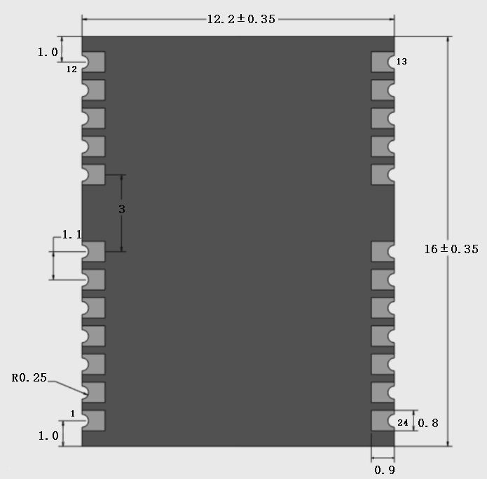
GUC300 has 2 rows of pins with a 0.3 mm pin spacing. A row has 12 pins.
-
The dimensions of GUC300:
- 12.2 ± 0.35 mm (W)
- 16 ± 0.35 mm (L)
- 2.3 ± 0.15 mm (H)
-
The thickness of PCB: 0.8±0.1 mm
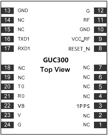
Pin definition
| Pin number | Symbol | Signal type | Description |
|---|---|---|---|
| 1 | NC | – | Pulled up and not connected |
| 2 | NC | – | Pulled up and not connected |
| 3 | 1PPS | O | PPS stands for Pulse Per Second |
| 4 | NC | – | Pulled up and not connected |
| 5 | NC | – | Pulled up and not connected |
| 6 | NC | – | Pulled up and not connected |
| 7 | NC | – | Pulled up and not connected |
| 8 | RESET_N | I | Reset pin, active low |
| 9 | VCC_RF | PO | RF power output, which can supply power for the external active antenna. If not used, it shall be pulled up. |
| 10 | GND | – | Ground |
| 11 | RF | I | RF signal input pin, which is connected to an external antenna |
| 12 | G | – | Ground |
| 13 | GND | – | Ground |
| 14 | NC | – | Pulled up and not connected |
| 15 | NC | – | Pulled up and not connected |
| 16 | TXD1 | O | Standby serial interface, which is used for transmitting data |
| 17 | RXD1 | I | Standby serial interface, which is used for receiving data |
| 18 | NC | – | Pulled up and not connected |
| 19 | NC | – | Pulled up and not connected |
| 20 | T0 | O | Serial interface for data transmission, which is used to output NMEA sentences |
| 21 | R0 | I | Serial interface for data reception, which is used to input PMTK/PQ commands and upgrade the firmware |
| 22 | VB | PI | Input of stand-by electric source |
| 23 | V | PI | Main power input |
| 24 | G | – | Ground |
Note: P indicates a power supply pin and I/O indicates an input/output pin. "*" indicates that the function is not supported currently.
Electrical parameters
Absolute electrical parameters
| Parameter | Description | Minimum value | Maximum value | Unit |
|---|---|---|---|---|
| Ts | Storage temperature | -40 | 90 | ℃ |
| V | Power supply voltage | -0.2 | 3.6 | V |
| Static electricity discharge voltage (human body model) | TAMB-25℃ | – | TBD | KV |
| Static electricity discharge voltage (machine model) | TAMB-25℃ | – | TBD | KV |
Normal working conditions
| Parameter | Description | Minimum value | Typical value | Maximum value | Unit |
|---|---|---|---|---|---|
| Ta | Working temperature | -40 | 25 | 85 | ℃ |
| V | Power supply voltage | 2.8 | 3.3 | 3.6 | V |
| VB | Standby voltage | 1.4 | 3.3 | 3.6 | V |
Power consumption in working mode
| Working mode | Project type | Average value | Peak value (typical value) | Unit |
|---|---|---|---|---|
| Capture | VDCDC_IN current | 27.3 | 32.48 | mA |
| Track | VDCDC_IN current | 27.1 | 33.25 | mA |
Note: When a power consumption test is conducted, the test voltage
VDCDC_INis 3.3V and the latest firmware version R3.2.10.0 Build 7099 is adopted.
Main performance parameters
| Parameter | Project conditions | Indicator | Unit |
|---|---|---|---|
| CN0 test value | The signal strength of the stimulator: -130 dBm (AVG) | 40±2 | dBc |
| TTFF (the module is static in the open environment) | Cold boot/hot start/recapture | 30/1.2/2 | s |
| Sensitivity test | Capture sensitivity/tracking sensitivity | -145/-158 | dBm |
| Positioning precision | Remain static in the open environment CEP50 | 2.5 | m |
| Antenna type | Antenna provided by the third party with the characteristic impedance of 50Ω | – | – |
Antenna information
Antenna type
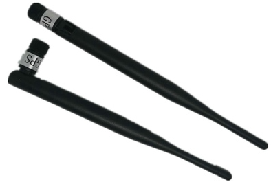
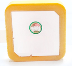
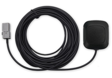
The module does not have its own onboard PCB antenna, which needs to be provided by a third party.
The antenna can be an external rod antenna, a passive ceramic antenna, an active antenna, a spiral antenna, etc. The antenna forms include monopole antenna, dielectric antenna, IFA antenna, and the like.
Antenna design requirements
- Ensure that the characteristic impedance of the transmission line is 50Ω.
- When designing the PCB layout, you should choose the most direct and shortest route, avoid routing through layers or holes and prevent rectangles and sharp angles.
- There is a good ground reference for the antenna, which stays away from other signal wires.
- It is recommended that you use the complete ground plane as the ground reference.
- Strengthen the connection between the ground around the antenna and the largest and most complete ground.
Packaging information and production instructions
Mechanical dimensions
Top and side view of GUC300 (unit: mm)
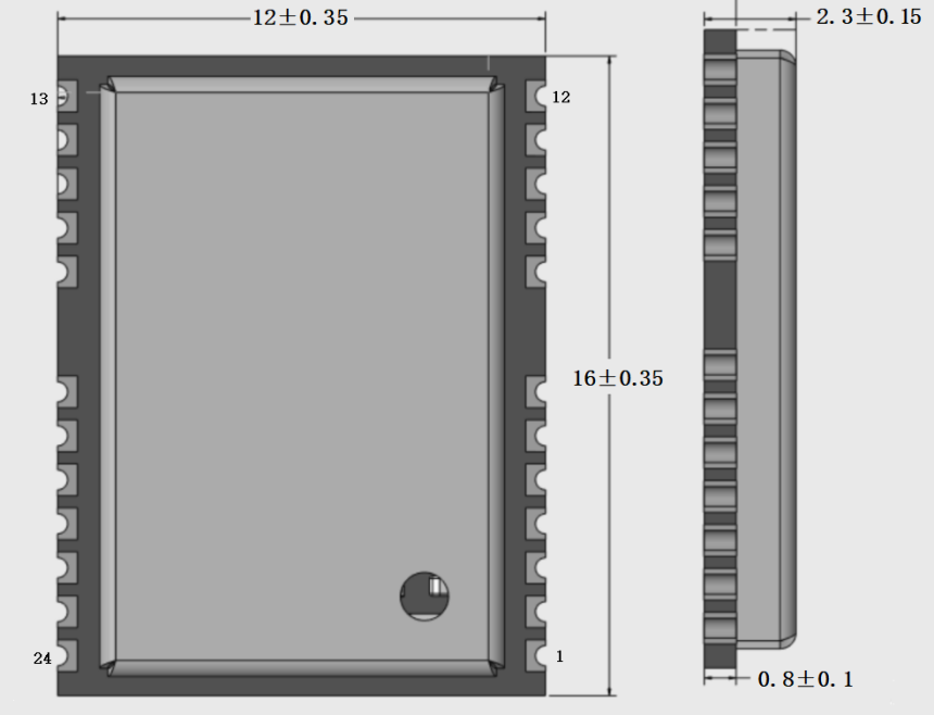
Note: The default outline dimension tolerance is ±0.35 mm, and the critical dimension tolerance is ±0.1 mm. If you have specific requirements on dimensions, make them clear in the module datasheet after communication.
Bottom view and recommended package
Bottom view of GUC300 (unit: mm)
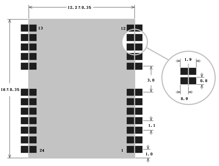
Recommended package (unit: mm)
Production instructions
-
The Tuya SMT module should be mounted by the SMT device. After being unpacked, it should be soldered within 24 hours. Otherwise, it should be put into the drying cupboard where the RH is not greater than 10%; or it needs to be packaged under vacuum again and the exposure time needs to be recorded (the total exposure time cannot exceed 168 hours).
- SMT devices:
- Mounter
- SPI
- Reflow soldering machine
- Thermal profiler
- Automated optical inspection (AOI) equipment
- Baking devices:
- Cabinet oven
- Anti-electrostatic and heat-resistant trays
- Anti-electrostatic and heat-resistant gloves
- SMT devices:
-
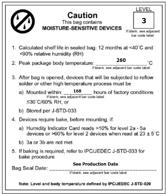
Storage conditions for a delivered module:
-
The moisture-proof bag must be placed in an environment where the temperature is below 40°C and the relative humidity is lower than 90%.
-
The shelf life of a dry-packaged product is 12 months from the date when the product is packaged and sealed.
-
There is a humidity indicator card (HIC) in the packaging bag.

-
-
The module needs to be baked in the following cases:
- The packaging bag is damaged before unpacking.
- There is no HIC in the packaging bag.
- After unpacking, circles of 10% and above on the HIC become pink.
- The total exposure time has lasted for over 168 hours since unpacking.
- More than 12 months have passed since the sealing of the bag.
-
Baking settings:
- Temperature: 40°C and ≤ 5% RH for reel package and 125°C and ≤5% RH for tray package (please use the heat-resistant tray rather than a plastic container)
- Time: 168 hours for reel package and 12 hours for tray package
- Alarm temperature: 50°C for reel package and 135°C for tray package
- Production-ready temperature after natural cooling: < 36°C
- Re-baking situation: If a module remains unused for over 168 hours after being baked, it needs to be baked again.
- If a batch of modules is not baked within 168 hours, do not use the wave soldering to solder them. Because these modules are Level-3 moisture-sensitive devices, they are very likely to get damp when exposed beyond the allowable time. In this case, if they are soldered at high temperatures, it may result in device failure or poor soldering.
-
In the whole production process, take electrostatic discharge (ESD) protective measures.
-
To guarantee the passing rate, it is recommended that you use the SPI and AOI to monitor the quality of solder paste printing and mounting.
Recommended oven temperature curve
Set oven temperatures according to the following temperature curve of reflow soldering. The peak temperature is 245°C.

-
A: Temperature axis
-
B: Time axis
-
C: Liquidus temperature: 217 to 220°C
-
D: Ramp-up slope: 1 to 3°C/s
-
E: Duration of constant temperature: 60 to 120s; the range of constant temperature: 150 to 200°C
-
F: Duration above the liquidus: 50 to 70s
-
G: Peak temperature: 235 to 245°C
-
H: Ramp-down slope: 1 to 4°C/s
Note: The above curve is just an example of the solder paste SAC305. For more details about other solder pastes, please refer to Recommended oven temperature curve in the solder paste specifications.
Storage conditions
MOQ and packaging information
| Product number | MOQ (pcs) | Shipping packaging method | The number of modules per reel | The number of reels per carton |
|---|---|---|---|---|
| GUC300 | 5600 | Tape reel | 1400 | 4 |
Is this page helpful?
YesFeedbackIs this page helpful?
YesFeedback


