TAU1113 Module Datasheet
System overview
General description
TAU1113 is a cost-effective low power GNSS positioning module based on a CYNOSURE III Lite GNSS SoC chip. It supports GPS/QZSS, BDS, Galileo, GLONASS, and SBAS. The module features SAW, LNA, flash memory as well as an antenna supervisor in a compact form factor.
TAU1113 is a versatile receiver that can be used with active and passive antennas, making it an excellent choice for a wide range of applications such as tracking, telematics, and navigation. The fast start-up in combined with the lower power consumption and the very low backup current make the TAU1113 particularly suitable for use in battery-powered devices, e.g., for asset tracking.
Features
- Versatile GNSS module supporting GPS/QZSS, BDS, Galileo, GLONASS, and SBAS
- Low current consumption of only 16 mA for GPS/QZSS
- Backup current of only 15 µA
- Active and passive antennas supported thanks to built-in SAW and LNA
- Supports Allystar’s free-of-charge A-GNSS service for minimal startup times
- Pin-compatible with previous generation TAU1103, TAU1105 and many mainstream GNSS modules
Table 1 TAU1113
| Product | GNSS | Feature | Interface | Accuracy | Grade | |||||||||||||||||
|---|---|---|---|---|---|---|---|---|---|---|---|---|---|---|---|---|---|---|---|---|---|---|
| GNSS system mode | Band (S/D/T) | GPS/QZSS | BDS | GLONASS | Galileo | NavIC | SBAS | Built-in LNA | Programmable (flash) | Data logging | D-GNSS | Oscillator | UART | I2C | USB | SPI | Meter | Sub-meter | Centimeter | Industrial | Automotive | |
| TAU1113-1010A00E | 1 | S | ● | ● | ● | ● | ● | ● | ● | T | ● | ● | ● | |||||||||
| 2 | S | ● | ● | ● | ● | ● | ● | ● | ● | T | ● | ● | ● | |||||||||
| 3 | S | ● | ● | ● | ● | ● | ● | ● | ● | T | ● | ● | ● | |||||||||
T = TCXO
Module photo
Figure 1 TAU1113 module
Block diagram
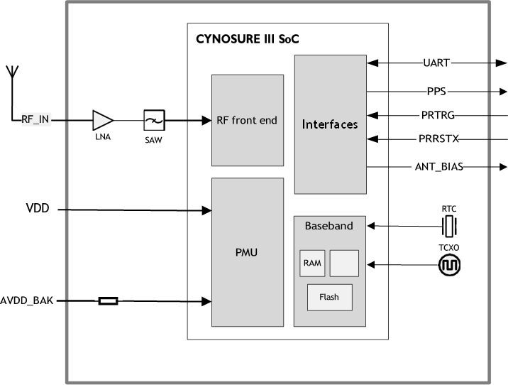
Figure 2 Block diagram
Specifications
Table 2 Specifications
| Parameter | Specification | ||
|---|---|---|---|
| GNSS channels | 88 in total | ||
| GNSS reception | GPS/QZSS: L1C/A | ||
| GLONASS: G1 | |||
| Galileo: E1 | |||
| BDS: B1I | |||
| SBAS: L1 (SDCM, WAAS, EGNOS, GAGAN and MSAS) | |||
| Updating rate | 5 Hz maximum | ||
| Position accuracy[1] | GNSS | 1.5m CEP | |
| GNSS (with SBAS) | <1.0m CEP | ||
| Velocity & Time accuracy | GNSS | 0.1 m/s CEP | |
| 1PPS | 20 ns | ||
| Sensitivity[2] | Cold start | -148 dBm | |
| Hot start | -156 dBm | ||
| Reacquisition | -158 dBm | ||
| Tracking | -163 dBm | ||
| Operating condition | Main voltage | 2.0V-3.63V | |
| Digital I/O voltage | 2.0V-3.63V | ||
| Backup voltage | 1.8V-3.63V | ||
| Power consumption | Tracking | GPS/QZSS+Galileo+GLONASS+SBAS | 21 mA @ 3.3V |
| GPS/QZSS+GLONASS+SBAS | 20 mA @ 3.3V | ||
| GPS/QZSS+Galileo+BDS+SBAS | 17 mA @ 3.3V | ||
| GPS/QZSS | 16 mA @ 3.3V | ||
| Acquisition | GPS/QZSS+Galileo+GLONASS+SBAS | 21 mA @ 3.3V | |
| GPS/QZSS+GLONASS+SBAS | 21 mA @ 3.3V | ||
| GPS/QZSS+Galileo+BDS+SBAS | 17 mA @ 3.3V | ||
| GPS/QZSS | 16 mA @ 3.3V | ||
| Standby mode | 15 μA @ 3.3V | ||
| Serial interface | UART | 1 | |
| Protocol | NMEA 0183 Protocol Ver.3.01/4.00/4.10 (Default) Cynosure GNSS Receiver Protocol | ||
| Operating limit | Velocity | 515 m/s | |
| Altitude | 18,000m | ||
| Antenna supervision | Antenna short circuit protection and open circuit detection | ||
| Operating temperature | -40°C to +85°C | ||
| Storage temperature | -40°C to +85°C | ||
| Package | 10.1x9.7x2.5 mm 18-pin LCC | ||
| Certification | RoHS, REACH, FCC, CE-RED | ||
* [1] Open sky condition.
* [2] Demonstrated with a good external LNA.
Table 3 Time to first fix (TTFF)
| Parameter | GPS/QZSS+Galileo+GLONASS+SBAS | GPS/QZSS+GLONASS+SBAS | GPS/QZSS+Galileo+BDS+SBAS | GPS/QZSS |
|---|---|---|---|---|
| Hot start | 2s | 2s | 2s | 1s |
| Cold start | 26s | 28s | 28s | 28s |
Pin description
Pin assignment
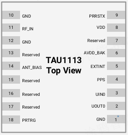
Figure 3 Pin assignment (top view)
* Pin 1 aligns to the circular hole on the module cover.
Detailed pin descriptions
Table 4 Detailed pin descriptions
| Function | Symbol | No. | I/O | Description |
|---|---|---|---|---|
| Power | VDD | 8 | Power | Main power supply voltage input. |
| GND | 1, 10, 12 | VSS | Assure a good GND connection to all GND pins of the module, preferably with a large ground plane. | |
| AVDD_BAK | 6 | Power | Backup power supply voltage input. Backup power is needed in order to enable warm and hot start features. Backup power is a must for system working. If no backup power is available, connect AVDD_BAK to the main power supply. |
|
| Antenna | RF_IN | 11 | I | RF signal input. Use a controlled impedance of 50Ω for the routing from RF_IN pin to the antenna or the antenna connector. |
| ANT_BIAS | 14 | O | Antenna bias voltage output. The ANT_BIAS pin can be used to power an external active antenna, and the current should be no more than 25 mA. | |
| UART | UOUT0 | 2 | O | UART0 serial data output. |
| UIN0 | 3 | I | UART0 serial data input. | |
| Other | PRTRG | 18 | I | Mode selection, or the trigger input in deep sleep mode to wake up the system. |
| PRRSTX | 9 | I | External reset, low active | |
| PPS | 4 | O | Setting for time pulse output (PPS). Leave it floating if not used. | |
| EXTINT | 5 | I | A trigger pin to external interrupt. Leave it floating if not used. | |
| Reserved | 7, 13, 15,16, 17 | - | Reserved. Leave it floating if not used. | |
Electrical characteristics
Absolute maximum rating
Table 5 Absolute rating
| Symbol | Parameter | Min. | Max. | Unit |
|---|---|---|---|---|
| VDD | Power input for the main power domain | -0.5 | 3.63 | V |
| AVDD_BAK | Power input for the backup power domain | -0.5 | 3.63 | V |
| VImax | Digital I/O pin input voltage | -0.5 | 3.6 | V |
| Tstorage | Storage temperature | -40 | 85 | °C |
| Tsolder | Solder reflow temperature | – | 260 | °C |
| VESD (HBM) | Maximum tolerable ESD level | – | 2000 | V |
IO characteristics
PRRSTX and PRTRG
Table 6 PRRSTX and PRTRG
| Symbol | Parameter | Condition | Min. | Typ. | Max. | Unit |
|---|---|---|---|---|---|---|
| IIZ | Input leakage current | - | - | - | +/-1 | μA |
| VIH | Input high voltage | - | AVDD_BAK×0.67 | - | AVDD_BAK | V |
| VIL | Input low voltage | - | 0 | - | AVDD_BAK×0.27 | V |
| VOH | Output high voltage | IOH = 5.3 mA, AVDD_BAK = 3.3V | 2.64 | - | - | V |
| IOH =1.2 mA, AVDD_BAK = 1.8V | 1.53 | - | - | V | ||
| VOL | Output low voltage | IOL = 3.9 mA, AVDD_BAK = 3.3V | - | - | 0.4 | V |
| IOL = 1.9 mA, AVDD_BAK = 1.8V | - | - | 0.45 | V | ||
Others
Table 7 Others
| Symbol | Parameter | Condition | Min. | Typ. | Max. | Unit |
|---|---|---|---|---|---|---|
| IIZ | Input leakage current | – | – | – | +/-1 | μA |
| VIH | Input high voltage | – | VDD×0.67 | – | VDD | V |
| VIL | Input low voltage | – | 0 | – | VDD×0.27 | V |
| VOH | Output high voltage | IOH = 5.3 mA, VDD = 3.3V | 2.64 | – | – | V |
| VOL | Output low voltage | IOL = 3.9 mA, VDD = 3.3V | – | – | 0.4 | V |
DC characteristics
Operating conditions
Table 8 Operating conditions
| Symbol | Parameter | Min. | Typ. | Max. | Unit |
|---|---|---|---|---|---|
| VDD | Power supply voltage | 2.0 | 3.3 | 3.63 | V |
| AVDD_BAK | Backup battery voltage | 1.8 | 3.3 | 3.63 | V |
| ICCmax | Maximum operating current @ VDD | – | – | 200 | mA |
| Tenv | Operating temperature | -40 | – | 85 | °C |
| VANT_BIAS | Antenna bias voltage | – | VDD-0.15[1] | – | V |
* [1] Condition: tested at high, low, and room temperature, with 0.1V deviation.
Power consumption
Table 9 Power consumption
| Parameter | Measure Pin | Typ. | Unit | |
|---|---|---|---|---|
| Tracking | GPS/QZSS+Galileo+GLONASS+SBAS | VDD[1] | 21 | mA |
| GPS/QZSS+GLONASS+SBAS | 20 | |||
| GPS/QZSS+Galileo+BDS+SBAS | 17 | |||
| GPS/QZSS | 16 | |||
| Acquisition | GPS/QZSS+Galileo+GLONASS+SBAS | 21 | ||
| GPS/QZSS+GLONASS+SBAS | 21 | |||
| GPS/QZSS+Galileo+BDS+SBAS | 17 | |||
| GPS/QZSS | 16 | |||
| Standby mode | AVDD_BAK[2] | 15 | μA | |
- [1] Condition: VDD = 3.3V @ Room Temperature. All Pins Open.
- [2] Condition: AVDD_BAK = 3.3V @ Room Temperature. All Pins Open.
Hardware description
Connecting power
In order to ensure the positioning performance, please control the ripple of the module power supply. It is recommended to use the LDO with a max output current above 100 mA.
If the power for the VDD pin is off, the real-time clock (RTC) and battery-backed RAM (BBR) are supplied through the AVDD_BAK pin. Thus, orbit information and time can be maintained, allowing a Hot or Warm start. If the AVDD_BAK needs to be supplied separately, please make sure the voltage is greater than or equal to the main voltage.
Note: If no backup supply is available, keep the AVDD_BAK pin to the main power supply. A floating state is not recommended.
Power on/off sequence
Initial system power on
To meet the requirement of controlling the power on/off sequence of the module, please connect the external reset pin (PRRSTX) to the Host.
When both backup and main supply power on from their off state, external reset (PRRSTX) must be active and hold more than 10 ms after both backup supply and main supply reach the minimum operating voltage. Initial system power-on sequence is illustrated in [Figure 4.]
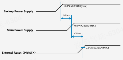
Figure 4 Initial system power-on sequence
Power off in application
Power off sequence is as follows:
- Run the power down command:
F1 D9 06 41 05 00 00 00 00 00 03 4F 64. - Power off the module after a 500 ms interval. Please ensure that the main power supply (VDD), backup power supply (AVDD_BAK) (if powered off), and IO power are all below 0.3V, to avoid the residual voltage from affecting the next power-on.
Note: The electrical characteristics of each EVK board vary, and so do the capacitance and load, which leads to differences in power-off time. Please confirm the power-off time of each EVK with Allystar technical support.
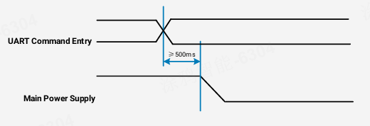
Figure 5 System power-off sequence
Antenna design
There is a built-in LNA and SAW in the GNSS module. It is recommended to use either a passive or an active antenna with a gain of less than 25 dB.
The module has built-in short circuit protection and open circuit detection functions, which can detect the antenna status of normal connection, open circuit, and short circuit, and send out the status prompt message in NMEA data.
-
Short circuit protection
The module includes internal short circuit antenna detection. Once an overcurrent is detected at the ANT_BIAS port, the module will cut off this power supply automatically to prevent permanent damages. -
Open circuit detection
The module can detect an open circuit in the antenna. Users can judge it from antenna status messages.
Reset and mode control
The operation mode of the GNSS module is controlled by PRRSTX (nRESET) and PRTRG (BOOT) pin. PRTRG pin cannot work alone when the module operates normally. PRRSTX pin can reset the system. Users MUST retain PRTRG and PRRSTX pins in the design to ensure that the Boot mode is accessible in case there is no firmware written in the embedded chip.
- Keep the PRTRG pin floating during system power-up or the external reset (PRRSTX from low to high), and the module will enter User Normal Mode.
- When the module powers up or PRRSTX from low to high, the module will execute an external reset. (If the power for AVDD_BAK is always on, the external reset will not affect the ephemeris data in the backup domain)
- Drive the PRTRG pin to low or connect PRTRG to GND directly (not by pull-down resistance) during system power-up or the external reset (PRRSTX from low to high), and the system enters BootROM Command Mode at PRTRG pin being released from low to floating state, and ready for firmware upgrading command.
When connecting PRRSTX and PRTRG to any host IO, DO NOT use the pull-up or pull-down resistance.
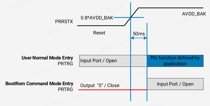
Figure 6 Timing of mode entry with the host controller
Default message
Table 10 Default messages
| Interface | Settings |
|---|---|
| UART output | 9600 baud, 8 data bits, no parity bit, 1 stop bit. Configured to transmit both NMEA and HD Binary protocols, but only the following NMEA (and no HD Binary sentence) messages have been activated at start-up: GGA, GSA, GSV, RMC, ZDA, TXT-ANT |
| UART input | 9600 baud, 8 data bits, no parity bit, 1 stop bit, autobauding disabled. Automatically accepts the following protocols without the need for explicit configuration: HD binary sentence, NMEA The GNSS receiver supports interleaved HD Binary and NMEA messages. |
| Timepulse (1 Hz Nav) |
1 pulse per second, synchronized at the rising edge, pulse length 100 ms. |
* Refer to GNSS_Protocol_Specification for information about other settings.
When the module is applied to the specific application, users can shut off the main power in order to further reduce the power consumption. To avoid the high level of serial interface influencing the normal operation, it is highly suggested to cut off the serial port when the main power is shut off. Otherwise, please set the serial port to input mode or high impedance state with a pull-down resistor.
Mechanical specification
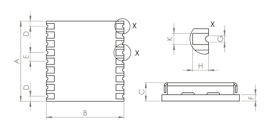
Figure 7 Dimensions
Table 11 Dimensions
| Symbol | Min. (mm) | Typ.(mm) | Max. (mm) |
|---|---|---|---|
| A | 9.9 | 10.1 | 10.3 |
| B | 9.5 | 9.7 | 9.9 |
| C | 2.3 | 2.5 | 2.7 |
| D | 0.55 | 0.65 | 0.95 |
| E | 1.0 | 1.1 | 1.2 |
| F | 0.6 | 0.8 | – |
| G | 0.4 | 0.5 | 0.6 |
| H | 0.8 | 0.9 | 1.0 |
| K | 0.7 | 0.8 | 0.9 |
Referecnce design
Minimal design
The minimal design of TAU1113 is shown below. The 39 nH inductor is used only when an active antenna is connected, and no need for a passive antenna. The characteristic impedance from the RF_IN pin to the antenna connector should be 50Ω.
Note: Do not keep the AVDD_BAK pin open. There is no diode between AVDD_BAK and VDD inside the module. The AVDD_BAK can be powered by VDD through an external diode, or an external independent power supply.
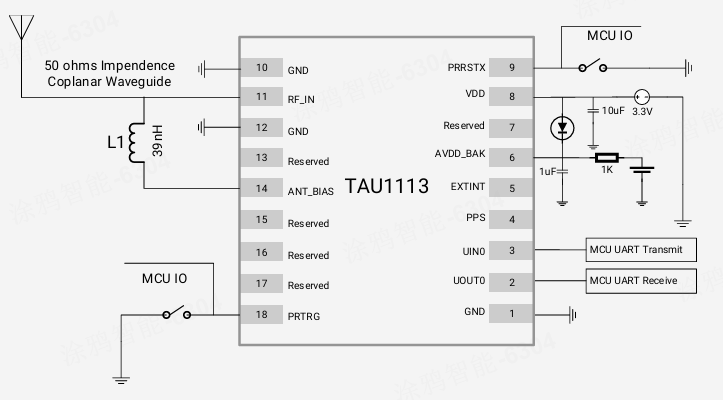
Figure 8 Minimal application diagram
PCB footprint reference
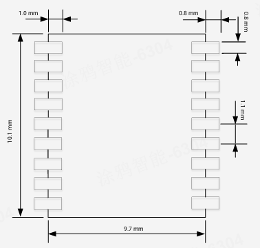
Figure 9 PCB Footprint Reference
Layout notes
- A decoupling capacitor should be placed close to the VDD pin of the module, and the width of power routing should be more than 0.5 mm.
- The width of RF routing between the RF port and the antenna interface should be wider than 0.2 mm. The characteristic impedance of RF routing between the RF port and antenna interface should be controlled to 50Ω.
- It is recommended that the routing from the RF port to the antenna interface refers to the second layer, and no routing is recommended on the layer.
- Do not place the module close to any EMI source, like an antenna, RF routing, DC/DC or power conductor, clock signal, or other high-frequency switching signal, etc. It is optimal to fill all the bottom of the module with ground plane.
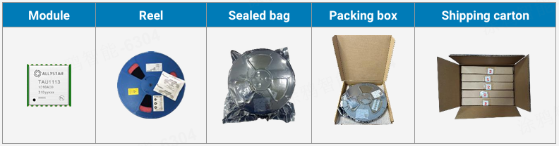
Product packaging and handling
Packaging
Packaging notes
TAU1113 GNSS module is a Moisture Sensitive Device (MSD) and Electrostatic Sensitive Device (ESD). During the packing and shipping, it is strictly required to take appropriate MSD handling instructions and precautions. The table below shows the general packing hierarchy for the standard shipment.
Table 12 Packing hierarchy
Tape and reel
TAU1113 modules are delivered as hermetically sealed, reeled tapes in order to enable efficient production, production lot set-up, and tear-down. The figure below shows the tape dimensions.
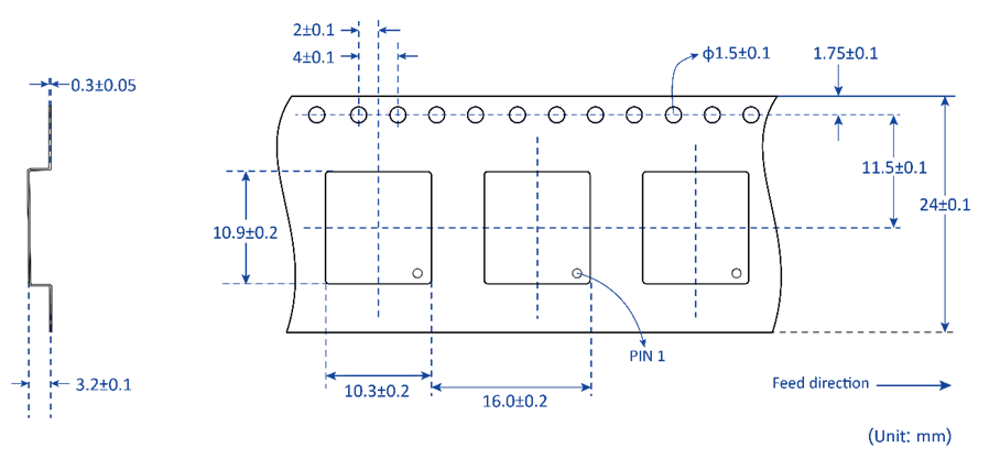
Figure 10 Tape dimensions
The TAU1113 modules are deliverable in quantities of 1000 pcs on a reel. The figure below shows the dimensions of a reel for TAU1113.
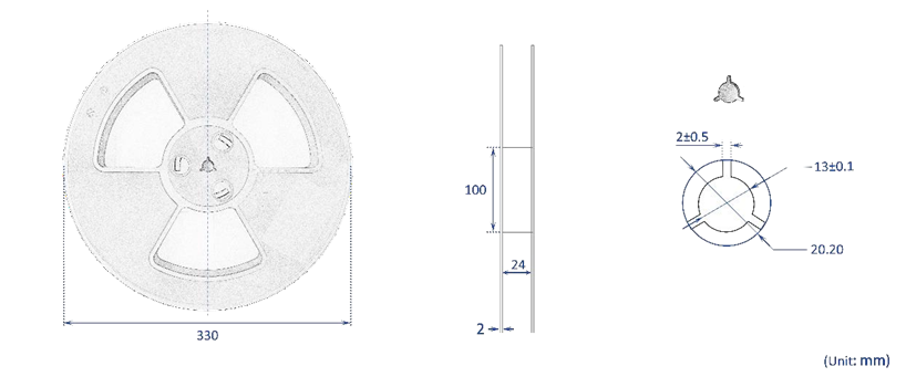
Figure 11 Reel dimensions
Shipment packaging
The reels of TAU1113 are packed in sealed bags in packing boxes and shipped by shipping cartons. Up to five boxes (5000 pcs in total) can be packed in one shipping carton.
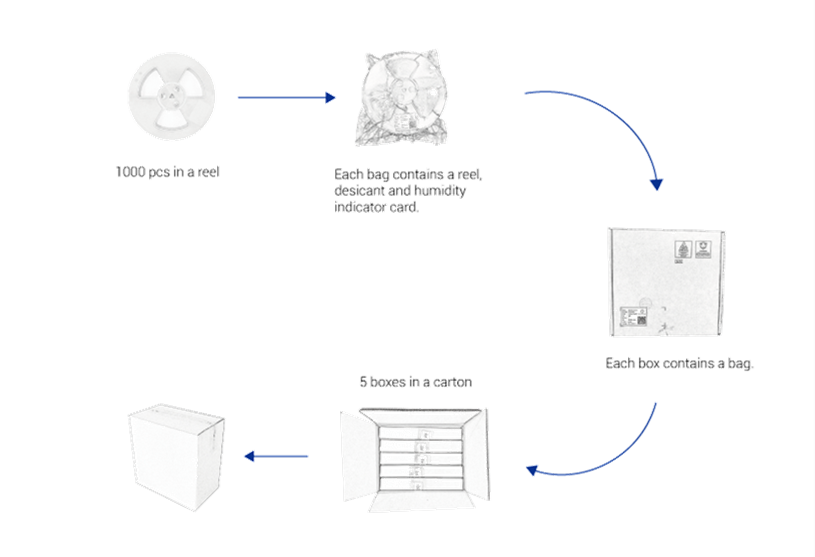
Figure 12 Packaging
Storage
In order to prevent moisture intake and protect against electrostatic discharge, TAU1113 is packaged together with a humidity indicator card and desiccant to absorb humidity.
Handling
ESD handling precautions
The TAU1113 module that contains highly sensitive electronic circuitry is the Electrostatic Sensitive Device (ESD). Observe precautions for handling! Failure to observe these precautions may result in severe damage to the GNSS module!
-
Unless there is a galvanic coupling between the local GND (i.e. the workbench) and the PCB GND, then the first point of contact when handling the PCB must always be between the local GND and PCB GND.
-
Before mounting an antenna patch, connect the ground of the device.
-
When handling the RF pin, do not come into contact with any charged capacitors, and be careful when contacting materials that can develop charges (e.g. patch antenna ~10 pF, coax cable ~50 - 80 pF/m, soldering iron …)
-
To prevent electrostatic discharge through the RF input, do not touch any exposed antenna area. If there is any risk that such an exposed antenna area is touched in non-ESD protected work area, implement proper ESD protection measures in the design.
-
When soldering RF connectors and patch antennas to the receiver’s RF pin, make sure to use an ESD-safe soldering iron (tip).

ESD protection measures
This series of GNSS positioning modules is sensitive to static electricity. Whenever handling the module, particular care must be exercised to reduce the risk of electrostatic charges. In addition to standard ESD safety practices, the following measures should be taken into account.
- Adds ESD protective device to the RF input part to prevent electrostatics discharge.
- Do not touch any exposed antenna area.
- Adds ESD protective device to the UART interface.
Moisture sensitivity level
The Moisture Sensitivity Level (MSL) of the GNSS modules is MSL3.
Labeling and ordering information
Labeling and ordering information help customers get more about Allystar products.
Labeling

| Symbol | Explanation | Instance |
|---|---|---|
| TAUXXXX | Product model | TAU1113 |
| 1010A00 | Product specification | 1010A00 |
| aaayybbbssss | Serial number | 351190010001 |
Ordering info
Table 13 Ordering codes
| Ordering No. | Product Information |
|---|---|
| TAU1113-1010A00E[1] | Concurrent GNSS LCC Module, TCXO, Flash, 10.1*9.7 mm, 1000pieces/reel. |
* [1] See Table 1 for the GNSS systems supported.
Is this page helpful?
YesFeedbackIs this page helpful?
YesFeedback


