MCU Integration Protocol for Gateway
Tuya Wi-Fi serial port protocol is a customized protocol for Wi-Fi modules. It is used for serial port communication between Tuya Wi-Fi modules and other MCU serial ports.
The architecture diagram is shown as follows.

Serial communication convention
- Baud: 115200
- Data bit: 8
- Parity check: none
- Stop bit: 1
- Data flow control: none
- MCU: the control chip of the control board, connecting to the Tuya module through the serial port
Frame format
| Field | Length (byte) | Description |
|---|---|---|
| Header | 2 | It is fixed as 0x55aa |
| Version | 1 | MCU software version number used for upgrading and extension |
| Command | 1 | Specific command |
| Data length | 2 | In big-endian mode |
| Data | Depend on specific data | Data transmitted |
| Checksum | 1 | Start from the header, add up all the bytes, and then divide the sum by 256 to get the remainder |
Data unit format
| Field | Bytes | Description |
|---|---|---|
| dpid | 1 | The identifier of a DP (DP ID). |
| type | 1 | It indicates the data type of a DP defined on the Tuya IoT Development Platform.
|
| len | 2 | The length is the number of bytes of the value. |
| value | 1/2/4/N | Represented in hexadecimal format. Data greater than one byte is transmitted in big-endian format. |
Basic protocol
Query product information
Product information consists of product ID (PID) and the MCU software version.
- PID: Corresponding to the product ID (PID) on the Tuya IoT Platform. It is generated by the Tuya IoT Platform to record product information in the cloud.
- MCU software version number: Defined as dot-decimal notation in the format of
x.x.x(0 ≤ x ≤ 99), and x is a decimal digit.
The module sends the following command:
| Field | Length (byte) | Description |
|---|---|---|
| Header | 2 | 0x55aa |
| Version | 1 | The following two versions are supported:
|
| Command | 1 | 0x01 |
| Data length | 2 | 0x0000 |
| Data | 0 | None |
| Checksum | 1 | Start from the header, add up all the bytes, and then divide the sum by 256 to get the remainder |
For example, 0x55aa 00 01 0000 00
The MCU returns the following command:
| Field | Length (byte) | Description |
|---|---|---|
| Header | 2 | 0x55aa |
| Version | 1 | 0x00 or 0x01 |
| Command | 1 | 0x01 |
| Data length | 2 | N |
| Data | Depend on specific data | See the example |
| Checksum | 1 | Start from the header, add up all the bytes, and then divide the sum by 256 to get the remainder |
For example, {"v":"1.0.0", "m":1, "cap":0, "p":"mhnmpqzf7ntzm***", "n":0, "s":0, "a":0}
-
V: the version number of MCU. For example, 1.0.0. -
m: pairing method.0: default pairing1: low power consumption2: special pairing
-
cap: Capabilities supported by the device. The value has been converted from hexadecimal to decimal. The corresponding functions of the bits are as follows:-
bit0: local group -
bit1: local scenario -
bit2: data point (DP) -
bit3: SIG mesh -
bit4: MCU upgrade -
bit5: group control command withsub_id -
bit6: Bluetooth serial port pairing, with the access point (AP) mode by defaultNote: For example, the device does not support local groups (
bit0is 0) or local scenario (bit1is 0), but supports DPs (bit2is 1). The hexadecimal data is0000 0000 0000 0100, that is, thecapvalue is 4.
-
-
p: product ID (PID). The PID in the example ismhnmpqzf7ntzm***. -
n(optional): pairing mode.-
Without this field: Switch between SmartConfig and AP pairing modes.
-
0: Indicates that both SmartConfig and AP pairing modes are available.
Note: After this pairing mode is selected, the command operation in the Reset Wi-Fi and select the pairing mode section will be invalid. The SmartConfig and AP pairing mode will remain after reset.
-
1: Only supports AP pairing mode.
Note: In this mode, the pairing can only be implemented through AP connection. After this pairing mode is selected, the command operation in the Reset Wi-Fi and select the pairing mode section will be invalid. The AP pairing mode will remain after reset.
-
-
s(optional): indicates whether the gateway is a security gateway and requires security capability support. Security capability is not supported by default.- 0: general gateway without security capability.
- 1: security gateway with security capability.
-
g (optional): Configures the gateway’s capability to access sub-devices. If this field is absent, all capabilities are enabled by default. This field can be left unconfigured.
- bit0: Whether to support sub-device access via the subpieces protocol.
- bit1: Bluetooth sub-device (this capability is enabled by default on some firmware and cannot be disabled).
-
a(optional): device function capability value. The data is 1 byte, equivalent to 8 bits, and each bit corresponds to a function. The MCU must use the corresponding function.bit0: When it indicates the security gateway function, determine whether the security alarm message is displayed. 0 means not supported, and 1 means supported.
Note: For the newly connected gateway,
bit0shall be set to 1 to reduce the MCU development workload. The corresponding command is0xC104.- bit1: Reserved data points. 0 shall be entered by default.
- bit2: Whether the LED indicator behavior and button functions are consistent with the gateway. 1 indicates consistent (with the gateway), 0 indicates the legacy scheme (takes effect when the module operates in Wi-Fi + Bluetooth LE mode).
- bit3~bit7: Reserved data points. 0 shall be entered by default.
Query working mode of the module set by MCU
The working mode of the module mainly includes how to indicate Wi-Fi working status and how to reset the Wi-Fi network. There are two cases.
-
The coordinated processing of the MCU and module
- Wi-Fi working status is displayed by the MCU.
- Wi-Fi reset: The MCU detects the Wi-Fi reset requirement, and through the serial port, notifies the module to reset.
-
The self-processing mode of the module
- Wi-Fi working status is displayed by the LED driven by Wi-Fi GPIO pin.
- Wi-Fi reset: The Wi-Fi is reset by detecting GPIO input requirement. Wi-Fi detects the low level of GPIO input pin for more than 5 seconds to trigger the Wi-Fi reset. The GPIO pins used by the indicators and buttons are configured by the following commands.
The module sends the following command:
| Field | Length (byte) | Description |
|---|---|---|
| Header | 2 | 0x55aa |
| Version | 1 | 0x00 |
| Command | 1 | 0x02 |
| Data length | 2 | 0x0000 |
| Data | 0 | None |
| Checksum | 1 | Start from the header, add up all the bytes, and then divide the sum by 256 to get the remainder |
For example, 0x55aa 00 02 0000 01
The MCU returns the following command:
| Field | Length (byte) | Description |
|---|---|---|
| Header | 2 | 0x55aa |
| Version | 1 | 0x00 |
| Command | 1 | 0x02 |
| Data length | 2 |
|
| Data | 0/2 | The data length is 4, and the port range is 0–3, which represents A–D respectively. The pin range is 0–7.
|
| Checksum | 1 | Start from the header, add up all the bytes, and then divide the sum by 256 to get the remainder |
Example:
0x55aa 00 02 0000 04(coordinated processing of the MCU and the mode)0x55aa 00 02 0004 0103 0102 0C(self-processing of the module, indicator 0x0103: PB_3, and reset button 0x0102: PB_2)
Report the network status of the device
Note: If the working mode of the module is set to module self-processing, the MCU does not need to implement this protocol.
- When the module detects that the MCU reboots or is disconnected and then go back online, the module will send the Wi-Fi status to the MCU.
- When the Wi-Fi status of the module changes, the Wi-Fi status is sent to the MCU.
| Network status of device | Description | Status value |
|---|---|---|
| Status 1 | SmartConfig pairing status | 0x00 |
| Status 2 | AP pairing status | 0x01 |
| Status 3 | Wi-Fi has been configured, but not connected to the router | 0x02 |
| Status 4 | Wi-Fi has been configured, and connected to the router | 0x03 |
| Status 5 | Wi-Fi has been connected to the router and the cloud | 0x04 |
| Status 6 | Wi-Fi device is in the low power consumption mode | 0x05 |
| Status 7 | Both SmartConfig and AP pairing status are available | 0x06 |
The status of LED indicator in module self-processing mode.
- 1: flicker at 250 milliseconds intervals
- 2: flicker at 1,500 milliseconds intervals
- 3: off
- 4: always on
- 5: always on
- 6: off
- 7: flicker at 250 milliseconds intervals
The module sends the following command:
| Field | Length (byte) | Description |
|---|---|---|
| Header | 2 | 0x55aa |
| Version | 1 | 0x00 |
| Command | 1 | 0x03 |
| Data length | 2 | 0x0001 |
| Data | 1 | Indicate the Wi-Fi working status. 0x00: status 1 0x01: status 2 0x02: status 3 0x03: status 4 0x04: status 5 0x05: status 6 0x06: status 7 |
| Checksum | 1 | Start from the header, add up all the bytes, and then divide the sum by 256 to get the remainder |
For example, 0x55aa 00 03 0001 00 03
The MCU returns the following command:
| Field | Length (byte) | Description |
|---|---|---|
| Header | 2 | 0x55aa |
| Version | 1 | 0x00 |
| Command | 1 | 0x03 |
| Data length | 2 | 0x0000 |
| Data | 0 | None |
| Checksum | 1 | Start from the header, add up all the bytes, and then divide the sum by 256 to get the remainder |
For example, 0x55aa 00 03 0000 02
Reset Wi-Fi
Note: If the working mode of the module is set to module self-processing, the MCU does not need to implement this protocol.
-
Status transfer of resetting Wi-Fi is shown as follows:
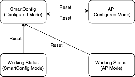
-
Reset Wi-Fi in self-processing mode: Wi-Fi detects the low level of GPIO input pin for more than 5 seconds to trigger Wi-Fi reset.
The MCU sends the following command:
| Field | Length (byte) | Description |
|---|---|---|
| Header | 2 | 0x55aa |
| Version | 1 | 0x00 |
| Command | 1 | 0x04 |
| Data length | 2 | 0x0000 |
| Data | 0 | None |
| Checksum | 1 | Start from the header, add up all the bytes, and then divide the sum by 256 to get the remainder |
For example, 0x55aa 00 04 0000 03
The module returns the following command:
| Field | Length (byte) | Description |
|---|---|---|
| Header | 2 | 0x55aa |
| Version | 1 | 0x00 |
| Command | 1 | 0x04 |
| Data length | 2 | 0x0000 |
| Data | 0 | None |
| Checksum | 1 | Start from the header, add up all the bytes, and then divide the sum by 256 to get the remainder |
For example, 0x55aa 00 04 0000 03
Reset Wi-Fi and select the pairing mode
Note: If the working mode of the module is set to module self-processing, the MCU does not need to implement this protocol.
You can implement this protocol selectively.
The MCU sends the following command:
| Field | Length (byte) | Description |
|---|---|---|
| Header | 2 | 0x55aa |
| Version | 1 | 0x00 |
| Command | 1 | 0x05 |
| Data length | 2 | 0x0001 |
| Data | 1 | 0x00: enter SmartConfig pairing mode 0x01: enter AP pairing mode |
| Checksum | 1 | Start from the header, add up all the bytes, and then divide the sum by 256 to get the remainder |
For example, 0x55aa 00 05 0001 00 05, enter SmartConfig pairing mode.
The module returns the following command:
| Field | Length (byte) | Description |
|---|---|---|
| Header | 2 | 0x55aa |
| Version | 1 | 0x00 |
| Command | 1 | 0x05 |
| Data length | 2 | 0x0000 |
| Data | 0 | None |
| Checksum | 1 | Start from the header, add up all the bytes, and then divide the sum by 256 to get the remainder |
For example, 0x55aa 00 05 0000 04
Enable the access of sub-devices
The app sends a network access command to the gateway, enabling the sub-device to access the network within a specified time.
The module sends the following command:
| Field | Length (byte) | Description |
|---|---|---|
| Header | 2 | 0x55aa |
| Version | 1 | 0x00 |
| Command | 1 | 0x06 |
| Data length | 2 | 0x0000 |
| Data | 0 | None |
| Checksum | 1 | Start from the header, add up all the bytes, and then divide the sum by 256 to get the remainder |
The MCU returns the following command:
| Field | Length (byte) | Description |
|---|---|---|
| Header | 2 | 0x55aa |
| Version | 1 | 0x00 |
| Command | 1 | 0x06 |
| Data length | 2 | 0x0000 |
| Data | 0 | None |
| Checksum | 1 | Start from the header, add up all the bytes, and then divide the sum by 256 to get the remainder |
Disable the access of sub-devices
The app sends a command to the gateway, disabling the access of sub-devices.
The module sends the following command:
| Field | Length (byte) | Description |
|---|---|---|
| Header | 2 | 0x55aa |
| Version | 1 | 0x00 |
| Command | 1 | 0x07 |
| Data length | 2 | 0x0000 |
| Data | 0 | None |
| Checksum | 1 | Start from the header, add up all the bytes, and then divide the sum by 256 to get the remainder |
The MCU returns the following command:
| Field | Length (byte) | Description |
|---|---|---|
| Header | 2 | 0x55aa |
| Version | 1 | 0x00 |
| Command | 1 | 0x07 |
| Data length | 2 | 0x0000 |
| Data | 0 | None |
| Checksum | 1 | Start from the header, add up all the bytes, and then divide the sum by 256 to get the remainder |
Add a sub-device
-
The MCU sends the network access request of the sub-device to Wi-Fi.
-
pk_typeis an optional field, and the default value is 1. -
The channel must be configured when the sub-device needs an OTA function. The default value is 10. Go to Hardware Development > Add custom firmware > Upgrade Channel.
Note: Incorrect channel configuration might cause exceptional OTA function.
The MCU sends the following command:
| Field | Length (byte) | Description |
|---|---|---|
| Header | 2 | 0x55aa |
| Version | 1 | 0x00 |
| Command | 1 | 0x08 |
| Data length | 2 | N |
| Data | N |
|
| Checksum | 1 | Start from the header, add up all the bytes, and then divide the sum by 256 to get the remainder |
The module returns the following command:
| Field | Length (byte) | Description |
|---|---|---|
| Header | 2 | 0x55aa |
| Version | 1 | 0x00 |
| Command | 1 | 0x08 |
| Data length | 2 | 0x0001 |
| Data | 1 | 0x00: Receive request 0x01: Reject request (To check whether the sub-device is actually successfully connected to the network, see Return the result of adding a device) |
| Checksum | 1 | Start from the header, add up all the bytes, and then divide the sum by 256 to get the remainder |
Delete a sub-device
The app sends a command to the gateway, disabling the access of sub-devices.
The module sends the following command:
| Field | Length (byte) | Description |
|---|---|---|
| Header | 2 | 0x55aa |
| Version | 1 | 0x00 |
| Command | 1 | 0x09 |
| Data length | 2 | None |
| Data | Depend on specific data |
|
| Checksum | 1 | Start from the header, add up all the bytes, and then divide the sum by 256 to get the remainder |
The MCU returns the following command:
| Field | Length (byte) | Description |
|---|---|---|
| Header | 2 | 0x55aa |
| Version | 1 | 0x00 |
| Command | 1 | 0x09 |
| Data length | 2 | 0x0000 |
| Data | 0 | None |
| Checksum | 1 | Start from the header, add up all the bytes, and then divide the sum by 256 to get the remainder |
Heartbeat detection
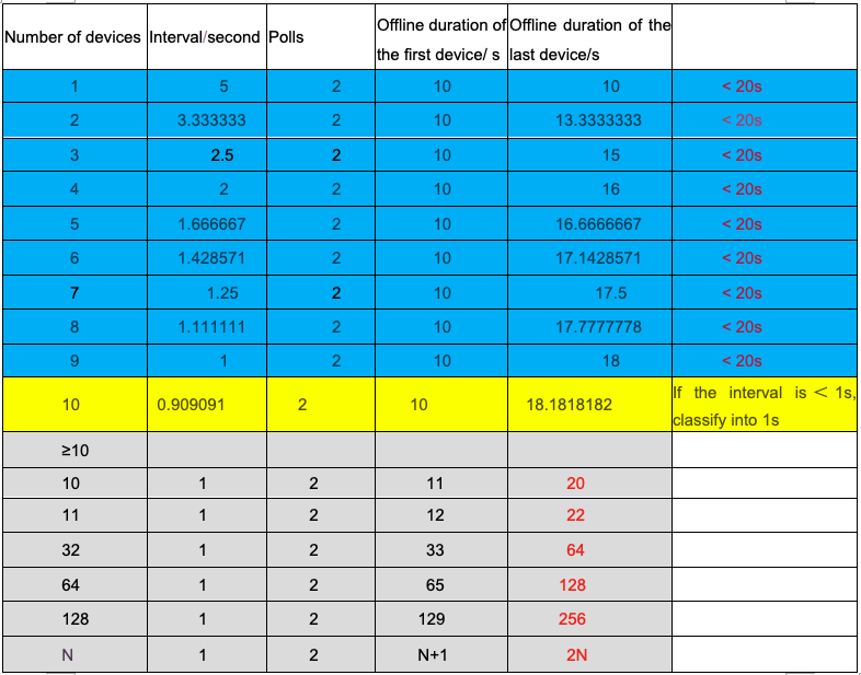
The Wi-Fi module regularly queries the heartbeat of the sub-device. The query cycle is related to the number of sub-devices. The more the sub-devices are, the more frequently the heartbeat of the sub-devices are queried.
The module sends the following command:
| Field | Length (byte) | Description |
|---|---|---|
| Header | 2 | 0x55aa |
| Version | 1 | 0x00 |
| Command | 1 | 0x0A |
| Data length | 2 | None |
| Data | Depend on specific data |
|
| Checksum | 1 | Start from the header, add up all the bytes, and then divide the sum by 256 to get the remainder |
The MCU returns the following command:
Note: An online device shall return its heartbeat. If it does not respond for two consecutive heartbeat cycles, it is considered offline.
| Field | Length (byte) | Description |
|---|---|---|
| Header | 2 | 0x55aa |
| Version | 1 | 0x00 |
| Command | 1 | 0x0A |
| Data length | 2 | None |
| Data | Depend on specific data |
|
| Checksum | 1 | Start from the header, add up all the bytes, and then divide the sum by 256 to get the remainder |
Query the status
Synchronize the sub-device status.
The module sends the following command:
| Field | Length (byte) | Description |
|---|---|---|
| Header | 2 | 0x55aa |
| Version | 1 | 0x00 |
| Command | 1 | 0x0B |
| Data length | 2 | None |
| Data | 0 | None |
| Checksum | 1 | Start from the header, add up all the bytes, and then divide the sum by 256 to get the remainder |
For the command returned by the MCU, see the Report status section.
Send a command
Send a control command.
- For DP commands and status data units, except the
rawtype, all other types belong to theobjtype data points. - Multiple data point commands can be sent at the same time.
- The asynchronous processing protocol is used to send the command, corresponding to the Report the status of the MCU.
DP command or status data unit is shown as follows.
| Data segment | Length (byte) | Description |
|---|---|---|
| dpid | 1 | DP number |
| type | 1 | The specific data type of a data point in the Tuya IoT Platform:
|
| len | 2 | The length corresponds to the byte number of the value (big-endian) |
| value | 1/2/4/N | Expressed with hex, and adopt big-endian transmission when there are more than 1 byte |
The module sends the following command:
| Field | Length (byte) | Description |
|---|---|---|
| Header | 2 | 0x55aa |
| Version | 1 | 0x00 |
| Command | 1 | 0x0C |
| Data length | 2 | None |
| Data | Depend on specific data |
|
| Checksum | 1 | Start from the header, add up all the bytes, and then divide the sum by 256 to get the remainder |
Report the status
The sub-device responds after receiving the command, or actively pushes the command after receiving the status change.
The MCU sends the following command:
| Field | Length (byte) | Description |
|---|---|---|
| Header | 2 | 0x55aa |
| Version | 1 | 0x00 |
| Command | 1 | 0x0D |
| Data length | 2 | None |
| Data | Depend on specific data |
|
| Checksum | 1 | Start from the header, add up all the bytes, and then divide the sum by 256 to get the remainder |
Add sub-devices to groups
Add sub-devices to local groups.
The module sends the following command:
| Field | Length (byte) | Description |
|---|---|---|
| Header | 2 | 0x55aa |
| Version | 1 | 0x00 |
| Command | 1 | 0x0E |
| Data length | 2 | None |
| Data | Depend on specific data |
|
| Checksum | 1 | Start from the header, add up all the bytes, and then divide the sum by 256 to get the remainder |
The MCU returns the following command:
| Field | Length (byte) | Description |
|---|---|---|
| Header | 2 | 0x55aa |
| Version | 1 | 0x00 |
| Command | 1 | 0x0E |
| Data length | 2 | None |
| Data | Depend on specific data |
|
| Checksum | 1 | Start from the header, add up all the bytes, and then divide the sum by 256 to get the remainder |
Remove a sub-device from a group
Remove a sub-device from a local group.
The module sends the following command:
| Field | Length (byte) | Description |
|---|---|---|
| Header | 2 | 0x55aa |
| Version | 1 | 0x00 |
| Command | 1 | 0x0F |
| Data length | 2 | None |
| Data | Depend on specific data |
|
| Checksum | 1 | Start from the header, add up all the bytes, and then divide the sum by 256 to get the remainder |
The MCU returns the following command:
| Field | Length (byte) | Description |
|---|---|---|
| Header | 2 | 0x55aa |
| Version | 1 | 0x00 |
| Command | 1 | 0x0F |
| Data length | 2 | None |
| Data | Depend on specific data |
|
| Checksum | 1 | Start from the header, add up all the bytes, and then divide the sum by 256 to get the remainder |
Get the GMT time of the system
The MCU sends the following command:
| Field | Length (byte) | Description |
|---|---|---|
| Header | 2 | 0x55aa |
| Version | 1 | 0x00 |
| Command | 1 | 0x10 |
| Data length | 2 | 0x0000 |
| Data | 0 | For example, 0x55aa 00 10 0000 0F |
| Checksum | 1 | Start from the header, add up all the bytes, and then divide the sum by 256 to get the remainder |
The module returns the following command:
| Field | Length (byte) | Description |
|---|---|---|
| Header | 2 | 0x55aa |
| Version | 1 | 0x00 |
| Command | 1 | 0x10 |
| Data length | 2 | 0x0007 |
| Data | 7 |
|
| Checksum | 1 | Start from the header, add up all the bytes, and then divide the sum by 256 to get the remainder |
Get the local time
The MCU sends the following command:
| Field | Length (byte) | Description |
|---|---|---|
| Header | 2 | 0x55aa |
| Version | 1 | 0x00 |
| Command | 1 | 0x11 |
| Data length | 2 | 0x0000 |
| Data | 0 | None |
| Checksum | 1 | Start from the header, add up all the bytes, and then divide the sum by 256 to get the remainder |
The module returns the following command:
| Field | Length (byte) | Description |
|---|---|---|
| Header | 2 | 0x55aa |
| Version | 1 | 0x00 |
| Command | 1 | 0x11 |
| Data length | 2 | 0x0008 |
| Data | 8 |
|
| Checksum | 1 | Start from the header, add up all the bytes, and then divide the sum by 256 to get the remainder |
Note:
- If the device is activated in mainland China, the local time is Beijing time (GMT+08:00).
- If the device is activated in other countries or regions, the local time is the time zone in which the device is.
Add devices in batches
Add multiple sub-devices of the same PID in batches. Maximum 32 sub-devices can be added in a single batch.
The MCU sends the following command:
| Field | Length (byte) | Description |
|---|---|---|
| Header | 2 | 0x55aa |
| Version | 1 | 0x00 |
| Command | 1 | 0x12 |
| Data length | 2 | None |
| Data | Depend on specific data |
|
| Checksum | 1 | Start from the header, add up all the bytes, and then divide the sum by 256 to get the remainder |
The module returns the following command:
| Field | Length (byte) | Description |
|---|---|---|
| Header | 2 | 0x55aa |
| Version | 1 | 0x00 |
| Command | 1 | 0x12 |
| Data length | 2 | None |
| Data | 1 |
|
| Checksum | 1 | Start from the header, add up all the bytes, and then divide the sum by 256 to get the remainder |
Return the result of adding a device
After the device is added, notify the MCU of the result.
The module sends the following command:
| Field | Length (byte) | Description |
|---|---|---|
| Header | 2 | 0x55aa |
| Version | 1 | 0x00 |
| Command | 1 | 0x13 |
| Data length | 2 | N |
| Data | N |
|
| Checksum | 1 | Start from the header, add up all the bytes, and then divide the sum by 256 to get the remainder |
The MCU returns the following command:
| Field | Length (byte) | Description |
|---|---|---|
| Header | 2 | 0x55aa |
| Version | 1 | 0x00 |
| Command | 1 | 0x13 |
| Data length | 2 | 0000 |
| Data | 0 | None |
| Checksum | 1 | Start from the header, add up all the bytes, and then divide the sum by 256 to get the remainder |
Send commands to control the group
The module sends the following command:
| Field | Length (byte) | Description |
|---|---|---|
| Header | 2 | 0x55aa |
| Version | 1 | 0x00 |
| Command | 1 | 0x14 |
| Data length | 2 | None |
| Data | Depend on specific data |
|
| Checksum | 1 | Start from the header, add up all the bytes, and then divide the sum by 256 to get the remainder |
The MCU returns the following command:
| Field | Length (byte) | Description |
|---|---|---|
| Header | 2 | 0x55aa |
| Version | 1 | 0x00 |
| Command | 1 | 0x14 |
| Data length | 2 | 0000 |
| Data | 0 | None |
| Checksum | 1 | Start from the header, add up all the bytes, and then divide the sum by 256 to get the remainder |
Wi-Fi functional test
Scan the specific SSID: tuya_mdev_test, and return the scanning result and signal strength percentage.
The MCU sends the following command:
| Field | Length (byte) | Description |
|---|---|---|
| Header | 2 | 0x55aa |
| Version | 1 | 0x00 |
| Command | 1 | 0x15 |
| Data length | 2 | 0x0000 |
| Data | Data | None |
| Checksum | 1 | Start from the header, add up all the bytes, and then divide the sum by 256 to get the remainder |
The module returns the following command:
| Field | Length (byte) | Description |
|---|---|---|
| Header | 2 | 0x55aa |
| Version | 1 | 0x00 |
| Command | 1 | 0x15 |
| Data length | 2 | 0x0002 |
| Data | 2 |
|
| Checksum | 1 | Start from the header, add up all the bytes, and then divide the sum by 256 to get the remainder |
Get Wi-Fi status
The MCU can get the Wi-Fi status with this command. For specific Wi-Fi status, see Report device network status. The gateway will not return the Wi-Fi status before the network initialization is completed.
The MCU sends the following command:
| Field | Length (byte) | Description |
|---|---|---|
| Header | 2 | 0x55aa |
| Version | 1 | 0x00 |
| Command | 1 | 0x16 |
| Data length | 2 | 0x0000 |
| Data | 0 | None |
| Checksum | 1 | Start from the header, add up all the bytes, and then divide the sum by 256 to get the remainder |
The module returns the following command:
| Field | Length (byte) | Description |
|---|---|---|
| Header | 2 | 0x55aa |
| Version | 1 | 0x00 |
| Command | 1 | 0x16 |
| Data length | 2 | 0x0001 |
| Data | 1 | Wi-Fi working status: 0x00: status 1 0x01: status 2 0x02: status 3 0x03: status 4 0x04: status 5 0x05: status 6 0x06: status 7 |
| Checksum | 1 | Start from the header, add up all the bytes, and then divide the sum by 256 to get the remainder |
Restore factory defaults (optional)
If a local (offline) command is sent to restore factory defaults, the cloud information and the local information will be out of sync. The command must be used when the device is online or before the device is activated for the first time.
The MCU sends the following command:
| Field | Length (byte) | Description |
|---|---|---|
| Header | 2 | 0x55aa |
| Version | 1 | 0x00 |
| Command | 1 | 0x17 |
| Data length | 2 | 0x0000 |
| Data | 0 | None |
| Checksum | 1 | Start from the header, add up all the bytes, and then divide the sum by 256 to get the remainder |
Report removal status
When receiving the command to remove a sub-device or restore the factory defaults, the gateway will report the status to the MCU.
- If only the removal command is received, the gateway will only remove the pairing, and will not delete the sub-device information. The next time you connect to the internet, the sub-device information will still be displayed on the app.
- If a command of restoring factory defaults is received, the gateway will remove the pairing and clear all sub-device information.
The module sends the following command:
| Field | Length (byte) | Description |
|---|---|---|
| Header | 2 | 0x55aa |
| Version | 1 | 0x00 |
| Command | 1 | 0x18 |
| Data length | 2 | 0x0001 |
| Data | 1 |
|
| Checksum | 1 | Start from the header, add up all the bytes, and then divide the sum by 256 to get the remainder |
Delete a sub-device locally
MCU sends a command to delete a sub-device.
The MCU sends the following command:
| Field | Length (byte) | Description |
|---|---|---|
| Header | 2 | 0x55aa |
| Version | 1 | 0x00 |
| Command | 1 | 0x19 |
| Data length | 2 | None |
| Data | Depend on specific data | For example, { "sub_id":"xxx" } |
| Checksum | 1 | Start from the header, add up all the bytes, and then divide the sum by 256 to get the remainder |
The module returns the following command:
| Field | Length (byte) | Description |
|---|---|---|
| Header | 2 | 0x55aa |
| Version | 1 | 0x00 |
| Command | 1 | 0x19 |
| Data length | 2 | 0x0001 |
| Data | 1 |
|
| Checksum | 1 | Start from the header, add up all the bytes, and then divide the sum by 256 to get the remainder |
Locally allow/disallow adding sub-devices
The MCU sends the following command:
| Field | Length (byte) | Description |
|---|---|---|
| Header | 2 | 0x55aa |
| Version | 1 | 0x00 |
| Command | 1 | 0x1A |
| Data length | 2 | 0x0003 |
| Data | 3 |
|
| Checksum | 1 | Start from the header, add up all the bytes, and then divide the sum by 256 to get the remainder |
The module returns the following command:
| Field | Length (byte) | Description |
|---|---|---|
| Header | 2 | 0x55aa |
| Version | 1 | 0x00 |
| Command | 1 | 0x1A |
| Data length | 2 | 0x0001 |
| Data | 1 |
|
| Checksum | 1 | Start from the header, add up all the bytes, and then divide the sum by 256 to get the remainder |
Get module memory
Get the remaining memory of the Wi-Fi module.
The MCU sends the following command:
| Field | Length (byte) | Description |
|---|---|---|
| Header | 2 | 0x55aa |
| Version | 1 | 0x03 |
| Command | 1 | 0x1B |
| Data length | 2 | 0x0000 |
| Data | 0 | None |
| Checksum | 1 | Start from the header, add up all the bytes, and then divide the sum by 256 to get the remainder |
The module returns the following command:
| Field | Length (byte) | Description |
|---|---|---|
| Header | 2 | 0x55aa |
| Version | 1 | 0x00 |
| Command | 1 | 0x1B |
| Data length | 2 | 0x0004 |
| Data | 4 | The data length is 4 bytes in big endian mode. For example, 00 00 28 00 represents the remaining memory is 10,240 bytes. |
| Checksum | 1 | Start from the header, add up all the bytes, and then divide the sum by 256 to get the remainder |
Query the list of sub-devices
The MCU can query the list of all sub-devices under the gateway. If greater than 255 bytes, the list data will be sent in packets.
The MCU sends the following command:
| Field | Length (byte) | Description |
|---|---|---|
| Header | 2 | 0x55aa |
| Version | 1 | 0x00 |
| Command | 1 | 0x1C |
| Data length | 2 | 0x0000 |
| Data | 0 | None |
| Checksum | 1 | Start from the header, add up all the bytes, and then divide the sum by 256 to get the remainder |
The module returns the following command:
| Field | Length (byte) | Description |
|---|---|---|
| Header | 2 | 0x55aa |
| Version | 1 | 0x00 |
| Command | 1 | 0x1C |
| Data length | 2 | None |
| Data | Depend on specific data |
|
| Checksum | 1 | Start from the header, add up all the bytes, and then divide the sum by 256 to get the remainder |
Remote upgrade service
The IoT Platform provides visualized configuration options, allowing users to choose the upgrade method. The module only serves as a data transmission channel that supports MCU upgrades and does not perform any data analysis.
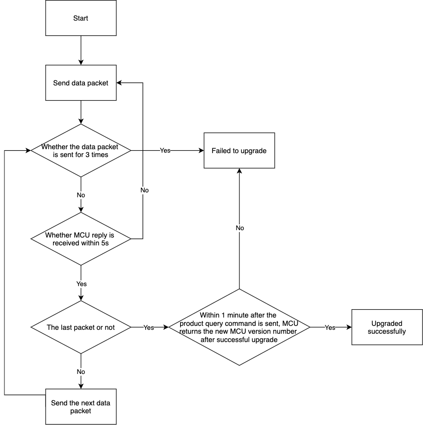
Note: After all the upgrade packets are sent, the Wi-Fi module sends the command 0x01 to query product information. The MCU shall reply with the software version number and the upgraded MCU software version number in the product information within one minute. The version number shall be consistent with that configured and upgraded on the Tuya IoT Platform.
-
MCU remote upgrade methods:
- App notification upgrade: You choose to upgrade or not when the app receives an upgrade prompt.
- App forced upgrade: There is an upgrade prompt on the app. You are required to upgrade the device before you continue to use it.
- App detects update: There is no upgrade prompt on the app. You must detect the relevant firmware version on the app and upgrade.
-
Auto upgrade (former silent upgrade): The app does not prompt the user to upgrade. The upgrade detection will be performed within one minute after the firmware is powered on. If a higher version upgrade packet is detected, it will be automatically downloaded and installed. Since the first power-on, upgrade detection will be performed every 24 hours.
-
MCU upgrade flowchart:
MCU starts upgrade
The module sends the following command:
| Field | Length (byte) | Description |
|---|---|---|
| Header | 2 | 0x55aa |
| Version | 1 | 0x00 |
| Command | 1 | 0x1D |
| Data length | 2 | 0x0004 |
| Data | 4 | Upgrade file size in the big-endian mode |
| Checksum | 1 | Start from the header, add up all the bytes, and then divide the sum by 256 to get the remainder |
The MCU returns the following command:
| Field | Length (byte) | Description |
|---|---|---|
| Header | 2 | 0x55aa |
| Version | 1 | 0x00 |
| Command | 1 | 0x1D |
| Data length | 2 | 0x0001 |
| Data | 1 | Upgrade packet transmission size:
|
| Checksum | 1 | Start from the header, add up all the bytes, and then divide the sum by 256 to get the remainder |
MCU upgrade packet transmission
- The data format of upgrade packet transmission: packet offset (unsigned short) + packet data.
- If MCU receives the frame with data length equal to 4 and the upgrade packet offset is equal to or greater than the size of firmware, the packet transmission ends.
The module sends the following command:
| Field | Length (byte) | Description |
|---|---|---|
| Header | 2 | 0x55aa |
| Version | 1 | 0x00 |
| Command | 1 | 0x1E |
| Data length | 2 | 0x0004+m in which m is the offset byte |
| Data | offset_addr (4 bytes)+ pack (m bytes) | offset_addr: packet offset address pack: packet content |
| Checksum | 1 | Start from the header, add up all the bytes, and then divide the sum by 256 to get the remainder |
For example, the file to be upgraded has 530 bytes. Under this circumstance, the MCU can skip the response to the last data packet.
-
For the first packet data, packet offset is 0x00000000, and the data packet length is 256.
0x55aa 00 1e 0104 00000000 xx…xx XX -
For the second packet data, packet offset is 0x00000100, and data packet length is 256.
0x55aa 00 1e 0104 00000100 xx…xx XX -
For the second to last packet data, packet offset is 0x00000200, and data packet length is 18.
0x55aa 00 1e 0016 00000200 xx…xx XX -
For the last packet data, packet offset is 0x00000212, and data packet length is 0.
0x55aa 00 1e 0004 00000212 XX
The MCU returns the following command:
| Field | Length (byte) | Description |
|---|---|---|
| Header | 2 | 0x55aa |
| Version | 1 | 0x00 |
| Command | 1 | 0x1E |
| Data length | 2 | 0x0000 |
| Data | 0 | None |
| Checksum | 1 | Start from the header, add up all the bytes, and then divide the sum by 256 to get the remainder |
A sub-device starts upgrade
The module sends the following command:
| Field | Length (byte) | Description |
|---|---|---|
| Header | 2 | 0x55aa |
| Version | 1 | 0x00 |
| Command | 1 | 0x1F |
| Data length | 2 | None |
| Data | Depend on specific data |
|
| Checksum | 1 | Start from the header, add up all the bytes, and then divide the sum by 256 to get the remainder |
The MCU returns the following command:
| Field | Length (byte) | Description |
|---|---|---|
| Header | 2 | 0x55aa |
| Version | 1 | 0x00 |
| Command | 1 | 0x1F |
| Data length | 2 | 0x0001 |
| Data | 1 | Packet size of the upgrade packet: 0x00: 256 bytes by default (compatible with old firmware) 0x01: 512 bytes 0x02: 1,024 bytes 0x03: 128 bytes |
| Checksum | 1 | Start from the header, add up all the bytes, and then divide the sum by 256 to get the remainder |
Sub-device upgrade packet transmission
- The data format of upgrade packet transmission: packet offset (unsigned short) + packet data.
- If MCU receives the frame with data length equal to 4 and the upgrade packet offset is equal to or greater than the size of firmware, the packet transmission ends.
The module sends the following command:
| Field | Length (byte) | Description |
|---|---|---|
| Header | 2 | 0x55aa |
| Version | 1 | 0x00 |
| Command | 1 | 0x20 |
| Data length | 2 | None |
| Data | Depend on specific data |
|
| Checksum | 1 | Start from the header, add up all the bytes, and then divide the sum by 256 to get the remainder |
Example: sub_id is 1234, the file size to be upgraded is 530 bytes. Under this circumstance, the MCU can skip the response to the last data packet.
-
For the first packet data, packet offset is 0x00000000, and the data packet length is 256.
0x55aa 00 20 0109 04 31 32 33 34 00000000 xx…xx XX -
For the second packet data, packet offset is 0x00000100, and data packet length is 256.
0x55aa 00 20 0109 04 31 32 33 34 00000100 xx…xx XX -
For the second to last packet data, packet offset is 0x00000200, and data packet length is 18.
0x55aa 00 20 001B 04 31 32 33 34 00000200 xx…xx XX -
For the last packet data, packet offset is 0x00000212, and data packet length is 0.
0x55aa 00 20 0009 04 31 32 33 34 00000212 XX
The MCU returns the following command:
| Field | Length (byte) | Description |
|---|---|---|
| Header | 2 | 0x55aa |
| Version | 1 | 0x00 |
| Command | 1 | 0x20 |
| Data length | 2 | 0x0000 |
| Data | 0 | None |
| Checksum | 1 | Start from the header, add up all the bytes, and then divide the sum by 256 to get the remainder |
Query the version number of a sub-device
The module sends the following command:
| Field | Length (byte) | Description |
|---|---|---|
| Header | 2 | 0x55aa |
| Version | 1 | 0x00 |
| Command | 1 | 0x21 |
| Data length | 2 | None |
| Data | Depend on specific data |
|
| Checksum | 1 | Start from the header, add up all the bytes, and then divide the sum by 256 to get the remainder |
The MCU returns the following command:
| Field | Length (byte) | Description |
|---|---|---|
| Header | 2 | 0x55aa |
| Version | 1 | 0x00 |
| Command | 1 | 0x21 |
| Data length | 2 | None |
| Data | Depend on specific data |
|
| Checksum | 1 | Start from the header, add up all the bytes, and then divide the sum by 256 to get the remainder |
Send commands to control the group (with sub_id)
The module sends the following command:
| Field | Length (byte) | Description |
|---|---|---|
| Header | 2 | 0x55aa |
| Version | 1 | 0x00 |
| Command | 1 | 0x22 |
| Data length | 2 | None |
| Data | Depend on specific data |
|
| Checksum | 1 | Start from the header, add up all the bytes, and then divide the sum by 256 to get the remainder |
The MCU returns the following command:
| Field | Length (byte) | Description |
|---|---|---|
| Header | 2 | 0x55aa |
| Version | 1 | 0x00 |
| Command | 1 | 0x22 |
| Data length | 2 | 0000 |
| Data | 0 | None |
| Checksum | 1 | Start from the header, add up all the bytes, and then divide the sum by 256 to get the remainder |
Pairing through the serial port (integrated)
The MCU sends the following command:
| Field | Length (byte) | Description |
|---|---|---|
| Header | 2 | 0x55aa |
| Version | 1 | 0x00 |
| Command | 1 | 0x23 |
| Data length | 2 | None |
| Data | Depend on specific data |
|
| Checksum | 1 | Start from the header, add up all the bytes, and then divide the sum by 256 to get the remainder |
The module returns the following command:
| Field | Length (byte) | Description |
|---|---|---|
| Header | 2 | 0x55aa |
| Version | 1 | 0x00 |
| Command | 1 | 0x23 |
| Data length | 2 | 0x0001 |
| Data | None |
|
| Checksum | 1 | Start from the header, add up all the bytes, and then divide the sum by 256 to get the remainder |
Pass-through pairing through the serial port (distributed)
Wi-Fi sends a broadcast packet
The data packet is passed from the Wi-Fi module to the MCU module for broadcast.
The module sends the following command:
| Field | Length (byte) | Description |
|---|---|---|
| Header | 2 | 0x55aa |
| Version | 1 | 0x00 |
| Command | 1 | 0x24 |
| Data length | 2 | None |
| Data | Depend on specific data | Broadcast packet data |
| Checksum | 1 | Start from the header, add up all the bytes, and then divide the sum by 256 to get the remainder |
The MCU returns the following command:
| Field | Length (byte) | Description |
|---|---|---|
| Header | 2 | 0x55aa |
| Version | 1 | 0x00 |
| Command | 1 | 0x24 |
| Data length | 2 | 0x0002 |
| Data | 2 | Return status: data[0]: 0x00: success 0x01: failure data[1]: 0: success fail: failure reason |
| Checksum | 1 | Start from the header, add up all the bytes, and then divide the sum by 256 to get the remainder |
The MCU sends pairing information
Data packets are transparently transmitted to Wi-Fi by the app through the MCU.
The MCU sends the following command:
| Field | Length (byte) | Description |
|---|---|---|
| Header | 2 | 0x55aa |
| Version | 1 | 0x00 |
| Command | 1 | 0x25 |
| Data length | 2 | None |
| Data | data | Encryption data |
| Checksum | 1 | Start from the header, add up all the bytes, and then divide the sum by 256 to get the remainder |
The module returns the following command:
| Field | Length (byte) | Description |
|---|---|---|
| Header | 2 | 0x55aa |
| Version | 1 | 0x00 |
| Command | 1 | 0x25 |
| Data length | 2 | 0x0000 |
| Data | 0 | None |
| Checksum | 1 | Start from the header, add up all the bytes, and then divide the sum by 256 to get the remainder |
Wi-Fi reports pairing information
Data packets are transparently transmitted to the app by the Wi-Fi through the MCU.
The module sends the following command:
| Field | Length (byte) | Description |
|---|---|---|
| Header | 2 | 0x55aa |
| Version | 1 | 0x00 |
| Command | 1 | 0x26 |
| Data length | 2 | N |
| Data | Depend on specific data | Encryption data |
| Checksum | 1 | Start from the header, add up all the bytes, and then divide the sum by 256 to get the remainder |
The MCU returns the following command:
| Field | Length (byte) | Description |
|---|---|---|
| Header | 2 | 0x55aa |
| Version | 1 | 0x00 |
| Command | 1 | 0x26 |
| Data length | 2 | 0x0000 |
| Data | None | |
| Checksum | 1 | Start from the header, add up all the bytes, and then divide the sum by 256 to get the remainder |
MCU connection status
The MCU will actively push the connection status with the mobile phone to the Wi-Fi module.
The MCU sends the following command:
| Field | Length (byte) | Description |
|---|---|---|
| Header | 2 | 0x55aa |
| Version | 1 | 0x00 |
| Command | 1 | 0x27 |
| Data length | 2 | 0x0001 |
| Data | 1 | Connection status: 0x00: disconnected 0x01: connection established |
| Checksum | 1 | Start from the header, add up all the bytes, and then divide the sum by 256 to get the remainder |
Wi-Fi module is disconnected actively
The module sends the following command:
| Field | Length (byte) | Description |
|---|---|---|
| Header | 2 | 0x55aa |
| Version | 1 | 0x00 |
| Command | 1 | 0x28 |
| Data length | 2 | 0x0000 |
| Data | 0 | None |
| Checksum | 1 | Start from the header, add up all the bytes, and then divide the sum by 256 to get the remainder |
The MCU returns the following command:
| Field | Length (byte) | Description |
|---|---|---|
| Header | 2 | 0x55aa |
| Version | 1 | 0x00 |
| Command | 1 | 0x28 |
| Data length | 2 | 0x0000 |
| Data | 0 | None |
| Checksum | 1 | Start from the header, add up all the bytes, and then divide the sum by 256 to get the remainder |
Query the DP status
The module sends the following command:
| Field | Length (byte) | Description |
|---|---|---|
| Header | 2 | 0x55aa |
| Version | 1 | 0x00 |
| Command | 1 | 0x29 |
| Data length | 2 | N |
| Data | Depend on specific data |
|
| Checksum | 1 | Start from the header, add up all the bytes, and then divide the sum by 256 to get the remainder |
The MCU returns status report.
Update online/offline status of the sub-device
The MCU sends the following command:
| Field | Length (byte) | Description |
|---|---|---|
| Header | 2 | 0x55aa |
| Version | 1 | 0x00 |
| Command | 1 | 0x2A |
| Data length | 2 | N |
| Data | Depend on specific data |
|
| Checksum | 1 | Start from the header, add up all the bytes, and then divide the sum by 256 to get the remainder |
The module returns the following command:
| Field | Length (byte) | Description |
|---|---|---|
| Header | 2 | 0x55aa |
| Version | 1 | 0x00 |
| Command | 1 | 0x2A |
| Data length | 2 | 0x0001 |
| Data | 1 | 0x00: success 0x01: failure |
| Checksum | 1 | Start from the header, add up all the bytes, and then divide the sum by 256 to get the remainder |
Get the MAC address of the module
The MCU sends the following command:
| Field | Length (byte) | Description |
|---|---|---|
| Header | 2 | 0x55aa |
| Version | 1 | 0x00 |
| Command | 1 | 0x2B |
| Data length | 2 | 0x0000 |
| Data | 0 | None |
| Checksum | 1 | Start from the header, add up all the bytes, and then divide the sum by 256 to get the remainder |
The module returns the following command:
| Field | Length (byte) | Description |
|---|---|---|
| Header | 2 | 0x55aa |
| Version | 1 | 0x00 |
| Command | 1 | 0x2B |
| Data length | 2 | 0x0007 |
| Data | Depend on specific data |
|
| Checksum | 1 | Start from the header, add up all the bytes, and then divide the sum by 256 to get the remainder |
Real-time reporting of record type status (with time)
- For record type sub-devices such as door locks, when reporting the DP status, the timestamp that generated these records shall be included.
- This is a synchronous upstream interface. After the MCU data is reported, the MCU waits for the module to return information to determine whether the sending operation is successful.
The module sends the following command:
| Field | Length (byte) | Description |
|---|---|---|
| Header | 2 | 0x55aa |
| Version | 1 | 0x00 |
| Command | 1 | 0x2C |
| Data length | 2 | None |
| Time | 7 |
|
| Data | Depend on specific data |
|
| Checksum | 1 | Start from the header, add up all the bytes, and then divide the sum by 256 to get the remainder |
The MCU returns the following command:
| Field | Length (byte) | Description |
|---|---|---|
| Header | 2 | 0x55aa |
| Version | 1 | 0x00 |
| Command | 1 | 0x2C |
| Data length | 2 | 0x0001 |
| Data | 1 | 0: success 1: failure |
| Checksum | 1 | Start from the header, add up all the bytes, and then divide the sum by 256 to get the remainder |
Query the binding status of sub-devices
The MCU sends the following command:
| Field | Length (byte) | Description |
|---|---|---|
| Header | 2 | 0x55aa |
| Version | 1 | 0x00 |
| Command | 1 | 0x2D |
| Data length | 2 | None |
| Data | Depend on specific data |
|
| Checksum | 1 | Start from the header, add up all the bytes, and then divide the sum by 256 to get the remainder |
The module returns the following command:
| Field | Length (byte) | Description |
|---|---|---|
| Header | 2 | 0x55aa |
| Version | 1 | 0x00 |
| Command | 1 | 0x2D |
| Data length | 2 | 0x0007 |
| Data | Depend on specific data |
|
| Checksum | 1 | Start from the header, add up all the bytes, and then divide the sum by 256 to get the remainder |
Query the information of sub-devices in the group
The MCU sends the following command:
| Field | Length (byte) | Description |
|---|---|---|
| Header | 2 | 0x55aa |
| Version | 1 | 0x00 |
| Command | 1 | 0x2E |
| Data length | 2 | N |
| Data | Depends on specific data |
|
| Checksum | 1 | Start from the header, add up all the bytes, and then divide the sum by 256 to get the remainder |
The module returns the following command:
| Field | Length (byte) | Description |
|---|---|---|
| Header | 2 | 0x55aa |
| Version | 1 | 0x00 |
| Command | 1 | 0x2E |
| Data length | 2 | None |
| Data | Depend on specific data | For example, {"gid":"xxx","sub_id":"xxxx" } |
| Checksum | 1 | Start from the header, add up all the bytes, and then divide the sum by 256 to get the remainder |
Report DPs locally changed in group
The MCU sends the following command:
| Field | Length (byte) | Description |
|---|---|---|
| Header | 2 | 0x55aa |
| Version | 1 | 0x00 |
| Command | 1 | 0x2F |
| Data length | 2 | N |
| Data | Depend on specific data |
|
| Checksum | 1 | Start from the header, add up all the bytes, and then divide the sum by 256 to get the remainder |
The module returns the following command:
| Field | Length (byte) | Description |
|---|---|---|
| Header | 2 | 0x55aa |
| Version | 1 | 0x00 |
| Command | 1 | 0x2F |
| Data length | 2 | 0x0001 |
| Data | 1 |
|
| Checksum | 1 | Start from the header, add up all the bytes, and then divide the sum by 256 to get the remainder |
Infrared (IR) functions
Send IR control code
- A single packet of IR code sent contains a maximum of 1,024 bytes.
- For scenarios where multiple control codes need to be sent, such as voice control or TV control, the module will output the current number of sent codes. After receiving the IR code, the MCU needs to wait for the module to send the next IR code. If it is not received within 250 ms, the currently received IR code will be sent.
- The default sending frequency of IR codes is 38 kHz.
- The module that sends the IR code shall wait for the MCU to respond with an acknowledge timeout of 1 second.
The module sends the following command:
| Field | Length (byte) | Description |
|---|---|---|
| Header | 2 | 0x55aa |
| Version | 1 | 0x00 |
| Command | 1 | 0x30 |
| Data length | 2 | None |
| Data | Depend on specific data |
|
| Checksum | 1 | Start from the header, add up all the bytes, and then divide the sum by 256 to get the remainder |
The MCU returns the following command:
| Field | Length (byte) | Description |
|---|---|---|
| Header | 2 | 0x55aa |
| Version | 1 | 0x00 |
| Command | 1 | 0x30 |
| Data length | 2 | 0x0002 |
| Data | 2 |
|
| Checksum | 1 | Start from the header, add up all the bytes, and then divide the sum by 256 to get the remainder |
Learn IR control code
The module sends the following command:
| Field | Length (byte) | Description |
|---|---|---|
| Header | 2 | 0x55aa |
| Version | 1 | 0x00 |
| Command | 1 | 0x31 |
| Data length | 2 | 0x0002 |
| Data | 2 |
|
| Checksum | 1 | Start from the header, add up all the bytes, and then divide the sum by 256 to get the remainder |
The MCU returns the following command:
| Field | Length (byte) | Description |
|---|---|---|
| Header | 2 | 0x55aa |
| Version | 1 | 0x00 |
| Command | 1 | 0x31 |
| Data length | 2 | N |
| Data | Depend on specific data |
|
| Checksum | 1 | Start from the header, add up all the bytes, and then divide the sum by 256 to get the remainder |
Example:
The module sends the following command:
55 AA 00 31 00 02 00 1E 50
The MCU returns the following command:
55 AA 00 31 00 75 00 00 00 94 FC 00 36 00 00 236f 236f 068e 0226 068e 0226 068e 0226 0226 0226 0226 0226 068e 0226 0226 0226 0226 0226 0226 0226 068e 0226 068e 0226 068e 0226 0226 0226 068e 0226 068e 0226 068e 0226 068e 0226 0226 0226 0226 0226 0226 0226 068e 0226 0226 0226 0226 0226 a9cf 236f 08ce 0226 82d5 82d5 85
Cancel learning
The module sends the following command:
| Field | Length (byte) | Description |
|---|---|---|
| Header | 2 | 0x55aa |
| Version | 1 | 0x00 |
| Command | 1 | 0x32 |
| Data length | 2 | 0 |
| Data | 0 | None |
| Checksum | 1 | Start from the header, add up all the bytes, and then divide the sum by 256 to get the remainder |
The MCU returns the following command:
| Field | Length (byte) | Description |
|---|---|---|
| Header | 2 | 0x55aa |
| Version | 1 | 0x00 |
| Command | 1 | 0x32 |
| Data length | 2 | 0x0001 |
| Data | MCU status of receiving control codes:
|
|
| Checksum | 1 | Start from the header, add up all the bytes, and then divide the sum by 256 to get the remainder |
Extended function
Weather service
- Weather service refers to obtaining weather data of the city where the device is activated, and currently supports 7-day weather forecast.
- After the MCU actively obtains and activates the weather service of the module, the module actively notifies the MCU regularly.
- For example, if request parameters are
w.temp,w.pm25and onlyw.tempis returned, the return parameters are less than the request parameters. In this case, check whether the request parameter name is correct. For more information, see the detailed parameter description of weather service. - For the field value of
w.condition, see Weather UTF-8 code table.
Example:
w.humidity: 69, w.temp: 32, w.pm25: 10, w.condition: cloudy (UTF-8 code E5A49A E4BA91)
55 AA 00 21 00 40 01 0A 77 2E 68 75 6D 69 64 69 74 79 00 04 00 00 00 45 06 77 2E 74 65 6D 70 00 04 00 00 00 20 06 77 2E 70 6D 32 35 00 04 00 00 00 10 0B 77 2E 63 6F 6E 64 69 74 69 6F 6E 01 06 E5 A4 9A E4 BA 91 1E
-
Input parameter:
{"codes":"w.temp","w.humidity", "w.sunRise", "w.sunSet", "t.local","w.date.3"} -
Return:
{"codes": "w.temp.0":13,"w.humidity.0":100, "w.sunRise.0":2019-12-28 06:54,""w.sunSet.0":2019-12-28 17:05,"w.temp.1":13,"w.humidity.1":100, "w.sunRise.1":2019-12-28 06:54,""w.sunSet.1":2019-12-28 17:05,"w.temp.2":13,"w.humidity.2":100,"w.sunRise.2":2019-12-28 06:54,""w.sunSet.2":2019-12-28 17:05,}
The module regularly updates the weather service
Enable to get the weather data
Enable to get the weather data. The update cycle is set by the MCU. The minimum update interval is 10 minutes, while the recommended standard update interval is 60 minutes. Considering the real-time nature of weather data, the maximum interval is 240 minutes.
The MCU sends the following command:
| Field | Length (byte) | Description |
|---|---|---|
| Header | 2 | 0x55aa |
| Version | 1 | 0x00 |
| Command | 1 | 0x33 |
| Data length | 2 | (1+1+(L+K)+(L+K)…) |
| Data | Depend on specific data |
|
| Checksum | 1 | Start from the header, add up all the bytes, and then divide the sum by 256 to get the remainder |
Example: 55 AA 00 33 00 2C 00 00 06 77 2E 74 65 6D 70 0A 77 2E 68 75 6D 69 64 69 74 79 0A 77 2E 70 72 65 73 73 75 72 65 06 77 2E 70 6D 32 35 05 77 2E 73 6F 32 B0
The module returns the following command:
| Field | Length (byte) | Description |
|---|---|---|
| Header | 2 | 0x55aa |
| Version | 1 | 0x00 |
| Command | 1 | 0x33 |
| Data length | 2 | 0x0003 |
| Data | 3 |
|
| Checksum | 1 | Start from the header, add up all the bytes, and then divide the sum by 256 to get the remainder |
Send weather data
After the weather data function is enabled, the module regularly sends the weather data. After the function is enabled, the data sending will be triggered immediately, and the data will be sent subsequently at the set time interval.
The module sends the following command:
| Field | Length (byte) | Description |
|---|---|---|
| Header | 2 | 0x55aa |
| Version | 1 | 0x00 |
| Command | 1 | 0x33 |
| Data length | 2 | (1+(LKTLV)+(LKTLV)+…) |
| Data | Depend on specific data |
|
| Checksum | 1 | Start from the header, add up all the bytes, and then divide the sum by 256 to get the remainder |
The MCU returns the following command:
| Field | Length (byte) | Description |
|---|---|---|
| Header | 2 | 0x55aa |
| Version | 1 | 0x00 |
| Command | 1 | 0x33 |
| Data length | 2 | 0x0001 |
| Data | 1 | Sub-command: 0x01 |
| Checksum | 1 | Start from the header, add up all the bytes, and then divide the sum by 256 to get the remainder |
The MCU gets weather service
- When the MCU actively gets the weather service, the MCU carries the required weather service data content.
- The frequency of using this command cannot be less than one minute, and multiple requests within one minute are processed only once.
- This command is used to confirm the data request. The data is still sent through command
0x3301.
The MCU sends the following command:
| Field | Length | Description |
|---|---|---|
| Header | 2 | 0x55aa |
| Version | 1 | 0x00 |
| Command | 1 | 0x33 |
| Data length | 2 | (1+1+(L+K)+(L+K)…) |
| Data | Depend on specific data |
|
| Checksum | 1 | Start from the header, add up all the bytes, and then divide the sum by 256 to get the remainder |
Example: 55 AA 00 33 00 2B 02 06 77 2E 74 65 6D 70 0A 77 2E 68 75 6D 69 64 69 74 79 0A 77 2E 70 72 65 73 73 75 72 65 06 77 2E 70 6D 32 35 05 77 2E 73 6F 32 B1
The module returns the following command:
| Field | Length (byte) | Description |
|---|---|---|
| Header | 2 | 0x55aa |
| Version | 1 | 0x00 |
| Command | 1 | 0x33 |
| Data length | 2 | 0x0002 |
| Data | 1 | Sub-command: 0x02 |
| 1 | Result: 0x00: success 0x01: failure |
|
| Checksum | 1 | Start from the header, add up all the bytes, and then divide the sum by 256 to get the remainder |
Send the time data with time zone system (GMT)
The MCU sends the following command:
| Field | Length (byte) | Description |
|---|---|---|
| Header | 2 | 0x55aa |
| Version | 1 | 0x00 |
| Command | 1 | 0x33 |
| Data length | 2 | 0x0001 |
| Data | 1 | Command: 0x03 |
| Checksum | 1 | Start from the header, add up all the bytes, and then divide the sum by 256 to get the remainder |
For example, 55 AA 00 33 00 01 03 36
The module returns the following command:
| Field | Length (byte) | Description |
|---|---|---|
| Header | 2 | 0x55aa |
| Version | 1 | 0x00 |
| Command | 1 | 0x33 |
| Data length | 2 | 1+2+1+7 |
| Data | 11 |
|
| Checksum | 1 | Start from the header, add up all the bytes, and then divide the sum by 256 to get the remainder |
Heartbeat query management
For scenarios that do not require heartbeat query, you can use this command to pause the heartbeat query.
The MCU sends the following command:
| Field | Length (byte) | Description |
|---|---|---|
| Header | 2 | 0x55aa |
| Version | 1 | 0x00 |
| Command | 1 | 0x33 |
| Data length | 2 | 0x0002 |
| Data | 1 | Sub-command: 0x04 |
| 1 | Heartbeat query status 0x01: recover heartbeat query 0x00: Disable heartbeat query |
|
| Checksum | 1 | Start from the header, add up all the bytes, and then divide the sum by 256 to get the remainder |
For example, 55 AA 00 33 00 02 04 00 38
The module returns the following command:
| Field | Length (byte) | Description |
|---|---|---|
| Header | 2 | 0x55aa |
| Version | 1 | 0x00 |
| Command | 1 | 0x33 |
| Data length | 2 | 1 |
| Data | 1 | Sub-command: 0x04 |
| Checksum | 1 | Start from the header, add up all the bytes, and then divide the sum by 256 to get the remainder |
Security and sensor extension protocol
This protocol contains security-related function commands, which only describes their content. For the detailed integration process, download the Connection Process of Security Gateway on the IoT Platform.
Set the arming mode
Set the current arming and disarming mode.
- After entering the arming mode, disarm and then set the arming mode again.
- At present, the arming delay time set by this command is invalid. The arming delay time is subject to the app settings. Pass 0 for the arming delay field data.
The MCU sends the following command:
| Field | Length (byte) | Description |
|---|---|---|
| Header | 2 | 0x55aa |
| Version | 1 | 0x00 |
| Command | 1 | 0xC0 |
| Data length | 2 | 1+N |
| Data | Depend on specific data |
|
| Checksum | 1 | Start from the header, add up all the bytes, and then divide the sum by 256 to get the remainder |
The module returns the following command:
| Field | Length (byte) | Description |
|---|---|---|
| Header | 2 | 0x55aa |
| Version | 1 | 0x00 |
| Command | 1 | 0xC0 |
| Data length | 2 | 2 |
| Data | 1 | Sub-command: 0x00 |
| 1 | Result: 00: success Others: failure |
|
| Checksum | 1 | Start from the header, add up all the bytes, and then divide the sum by 256 to get the remainder |
Get the current security information
Get the current security information.
The MCU sends the following command:
| Field | Length (byte) | Description |
|---|---|---|
| Header | 2 | 0x55aa |
| Version | 1 | 0x00 |
| Command | 1 | 0xC0 |
| Data length | 2 | 1 |
| Data | 1 | Sub-command: 0x01 |
| Checksum | 1 | Start from the header, add up all the bytes, and then divide the sum by 256 to get the remainder |
The module returns the following command:
| Field | Length (byte) | Description |
|---|---|---|
| Header | 2 | 0x55aa |
| Version | 1 | 0x00 |
| Command | 1 | 0xC0 |
| Data length | 2 | 1+N |
| Data | 1 | Sub-command: 0x01 |
| Depend on specific data |
|
|
| Checksum | 1 | Start from the header, add up all the bytes, and then divide the sum by 256 to get the remainder |
Synchronize security information
After the security information is set through the app, the module synchronizes the status to the MCU through this command.
The module sends the following command:
| Field | Length (byte) | Description |
|---|---|---|
| Header | 2 | 0x55aa |
| Version | 1 | 0x00 |
| Command | 1 | 0xC0 |
| Data length | 2 | 1+N |
| Data | 1 | Sub-command: 0x02 |
| Depend on specific data |
|
|
| Checksum | 1 | Start from the header, add up all the bytes, and then divide the sum by 256 to get the remainder |
The MCU returns the following command:
| Field | Length (byte) | Description |
|---|---|---|
| Header | 2 | 0x55aa |
| Version | 1 | 0x00 |
| Command | 1 | 0xC0 |
| Data length | 2 | 1 |
| Data | 1 | Sub-command: 0x02 |
| Checksum | 1 | Start from the header, add up all the bytes, and then divide the sum by 256 to get the remainder |
Synchronize device security events
The security event module synchronizes the status to the MCU through this command.
The module sends the following command:
| Field | Length (byte) | Description |
|---|---|---|
| Header | 2 | 0x55aa |
| Version | 1 | 0x00 |
| Command | 1 | 0xC0 |
| Data length | 2 | 1+N |
| Data | Sub-command | 0x03 |
| Depend on specific data |
|
|
| Checksum | 1 | Start from the header, add up all the bytes, and then divide the sum by 256 to get the remainder |
The MCU returns the following command:
| Field | Length (byte) | Description |
|---|---|---|
| Header | 2 | 0x55aa |
| Version | 1 | 0x00 |
| Command | 1 | 0xC0 |
| Data length | 2 | 1 |
| Data | Sub-command | 0x03 |
| Checksum | 1 | Start from the header, add up all the bytes, and then divide the sum by 256 to get the remainder |
Alarm status setting
In case of status change through the security standard DP32, the MCU shall synchronize the status to the module.
The MCU sends the following command:
| Field | Length (byte) | Description |
|---|---|---|
| Header | 2 | 0x55aa |
| Version | 1 | 0x00 |
| Command | 1 | 0xC1 |
| Data length | 2 | 2 |
| Data | Sub-command | 0x00 |
| Alarm status | 0: normal. Non-0: alarming |
|
| Checksum | 1 | Start from the header, add up all the bytes, and then divide the sum by 256 to get the remainder |
The module returns the following command:
| Field | Length (byte) | Description |
|---|---|---|
| Header | 2 | 0x55aa |
| Version | 1 | 0x00 |
| Command | 1 | 0xC1 |
| Data length | 2 | 2 |
| Data | Sub-command | 0x00 |
| Action result | 0: success Others: failure |
|
| Checksum | 1 | Start from the header, add up all the bytes, and then divide the sum by 256 to get the remainder |
Cancel alarm status synchronization
When the alarm is canceled through the app, the module synchronizes the status with this command to the MCU, and the MCU reports false through the security standard DP 2.
The module sends the following command:
| Field | Length (byte) | Description |
|---|---|---|
| Header | 2 | 0x55aa |
| Version | 1 | 0x00 |
| Command | 1 | 0xC1 |
| Data length | 2 | 2 |
| Data | 1 | Sub-command: 0x01 |
| 1 | 0: cancel the alarm | |
| Checksum | 1 | Start from the header, add up all the bytes, and then divide the sum by 256 to get the remainder |
The MCU returns the following command:
| Field | Length (byte) | Description |
|---|---|---|
| Header | 2 | 0x55aa |
| Version | 1 | 0x00 |
| Command | 1 | 0xC1 |
| Data length | 2 | 1 |
| Data | 1 | Sub-command: 0x01 |
| Checksum | 1 | Start from the header, add up all the bytes, and then divide the sum by 256 to get the remainder |
Synchronize device alarm information
When the environmental device DP or non-environmental device DP triggers a device alarm, the module uses this command to synchronize the alarm information to the MCU, and the MCU reports it through the security standard DP 26.
- Non-environmental device: It is related to arming and disarming, and only alarms when arming.
- Environmental device: It is irrelevant to arming and disarming. As long as it is triggered, it will alarm.
The module sends the following command:
| Field | Length (byte) | Description |
|---|---|---|
| Header | 2 | 0x55aa |
| Version | 1 | 0x00 |
| Command | 1 | 0xC1 |
| Data length | 2 | 1+N |
| Data | Sub-command | 0x02 |
| Depend on specific data |
|
|
| Checksum | 1 | Start from the header, add up all the bytes, and then divide the sum by 256 to get the remainder |
The MCU returns the following command:
| Field | Length (byte) | Description |
|---|---|---|
| Header | 2 | 0x55aa |
| Version | 1 | 0x00 |
| Command | 1 | 0xC1 |
| Data length | 2 | 1 |
| Data | 1 | Sub-command: 0x02 |
| Checksum | 1 | Start from the header, add up all the bytes, and then divide the sum by 256 to get the remainder |
Synchronize device alarm delay status
When the device is in the alarm delay status, the alarm delay status will be synchronized to the MCU through this command.
The module sends the following command:
| Field | Length (byte) | Description |
|---|---|---|
| Header | 2 | 0x55aa |
| Version | 1 | 0x00 |
| Command | 1 | 0xC1 |
| Data length | 2 | 2 |
| Data | 1 | Sub-command: 0x03 |
| 1 | Alarm delay status 0: alarm delay is not created 1: alarm delay is in progress 2: alarm delay is over |
|
| Checksum | 1 | Start from the header, add up all the bytes, and then divide the sum by 256 to get the remainder |
The MCU returns the following command:
| Field | Length (byte) | Description |
|---|---|---|
| Header | 2 | 0x55aa |
| Version | 1 | 0x00 |
| Command | 1 | 0xC1 |
| Data length | 2 | 1 |
| Data | 1 | Sub-command: 0x03 |
| Checksum | 1 | Start from the header, add up all the bytes, and then divide the sum by 256 to get the remainder |
Synchronize the new device alarm information
This command is to synchronize the new device alarm information. It is enabled with the bit 0 of the A field in the 01 command. After enabled, the security 0xc101 and 0xc102 commands do not need to be processed.
- There is currently no
GPfield. - Non-environmental device: the device is not related to environmental monitoring.
- Environmental device: the device is related to environmental monitoring.
- This command is used for alarm information synchronization. The data content sent by the module is not fixed, and the supported field data will be sent according to the available device functions.
Currently, fields for multi-zone gateway function are reserved. The field could not be returned.
The module sends the following command:
| Field | Length (byte) | Description |
|---|---|---|
| Header | 2 | 0x55aa |
| Version | 1 | 0x00 |
| Command | 1 | 0xC1 |
| Data length | 2 | 1+N |
| Data | 1 | Sub-command: 0x04 |
| Depend on specific data |
|
|
| Checksum | 1 | Start from the header, add up all the bytes, and then divide the sum by 256 to get the remainder |
The MCU returns the following command:
| Field | Length (byte) | Description |
|---|---|---|
| Header | 2 | 0x55aa |
| Version | 1 | 0x00 |
| Command | 1 | 0xC1 |
| Data length | 2 | 1 |
| Data | Sub-command | 0x04 |
| Checksum | 1 | Start from the header, add up all the bytes, and then divide the sum by 256 to get the remainder |
Synchronize the new device alarm status
This command is to synchronize the new device alarm information. It is enabled with the bit 0 of the A field in the 01 command.
The module sends the following command:
| Field | Length (byte) | Description |
|---|---|---|
| Header | 2 | 0x55aa |
| Version | 1 | 0x00 |
| Command | 1 | 0xC1 |
| Data length | 2 | 2 |
| Data | 1 | Sub-command: 0x05 |
| Data | 0: cancel the alarm 1: alarm in progress |
|
| Checksum | 1 | Start from the header, add up all the bytes, and then divide the sum by 256 to get the remainder |
The MCU returns the following command:
| Field | Length (byte) | Description |
|---|---|---|
| Header | 2 | 0x55aa |
| Version | 1 | 0x00 |
| Command | 1 | 0xC1 |
| Data length | 2 | 1 |
| Data | 1 | Sub-command: 0x05 |
| Checksum | 1 | Start from the header, add up all the bytes, and then divide the sum by 256 to get the remainder |
Appendix 1. Weather UTF-8 code table of condition
| Text | Hexadecimal | Text | Hexadecimal |
|---|---|---|---|
| Sunny | E699B4 | Heavy rain | E5A4A7 E99BA8 |
| Thunderstorm | E99BB7 E69AB4 | Sandstorm | E6B299 E5B098 E69AB4 |
| Light snow | E5B08F E99BAA | Snow | E99BAA |
| Freezing fog | E586BB E99BBE | Rainstorm | E69AB4 E99BA8 |
| Isolated showers | E5B180 E983A8 E998B5 E99BA8 | Dust | E6B5AE E5B098 |
| Thunder and lightning | E99BB7 E794B5 | Light showers | E5B08F E998B5 E99BA8 |
| Rain | E99BA8 | Sleet | E99BA8 E5A4B9 E99BAA |
| Dust devil | E5B098 E58DB7 E9A38E | Ice pellet | E586B0 E7B292 |
| Strong sandstorm | E5BCBA E6B299 E5B098 E69AB4 | Sand blowing | E689AC E6B299 |
| Light to moderate rain | E5B08F E588B0 E4B8AD E99BA8 | Mostly clear | E5A4A7 E983A8 E699B4 E69C97 |
| Fog | E99BBE | Showers | E998B5 E99BA8 |
| Heavy showers | E5BCBA E998B5 E99BA8 | Heavy snow | E5A4A7 E99BAA |
| Extraordinary rainstorm | E789B9 E5A4A7 E69AB4 E99BA8 | Blizzard | E69AB4 E99BAA |
| Hail | E586B0 E99BB9 | Light to moderate snow | E5B08F E588B0 E4B8AD E99BAA |
| Partly cloudy | E5B091 E4BA91 | Light snow shower | E5B08F E998B5 E99BAA |
| Moderate snow | E4B8AD E99BAA | Overcast | E998B4 |
| Needle ice | E586B0 E99288 | Downpour | E5A4A7 E69AB4 E99BA8 |
| Thundershower and hail | E99BB7 E998B5 E99BA8 E4BCB4 E69C89 E586B0 E99BB9 | Freezing rain | E586BB E99BA8 |
| Snow showers | E998B5 E99BAA | Light rain | E5B08F E99BA8 |
| Haze | E99CBE | Moderate rain | E4B8AD E99BA8 |
| Cloudy | E5A49A E4BA91 | Thundershower | E99BB7 E998B5 E99BA8 |
| Moderate to heavy rain | E4B8AD E588B0 E5A4A7 E99BA8 | Heavy to rainstorm | E5A4A7 E588B0 E69AB4 E99BA8 |
Appendix 2. Detailed parameter description of weather service
| Weather data parameter | Description | Mainland China | Outside mainland China | Forecast | Hexadecimal value |
|---|---|---|---|---|---|
| w.temp | Atmospheric temperature | Yes | Yes | 7-day forecast in mainland China | 77 2e 74 65 6d 70 |
| w.thigh | The highest temperature | No | Yes | 7-day forecast | 77 2e 74 68 69 67 68 |
| w.tlow | The lowest temperature | No | Yes | 7-day forecast | 77 2e 74 6c 6f 77 |
| w.humidity | Air humidity | Yes | Yes | 7-day forecast | 77 2e 68 75 6d 69 64 69 74 79 |
| w.condition | Weather conditions, such as sunny day, rain, and snow | Yes | Yes | 7-day forecast | 77 2e 63 6f 6e 64 69 74 69 6f 6e |
| w.conditionNum | Weather conditions, indicated by digital codes | Yes | Yes | 7-day forecast | 77 2e 63 6f 6e 64 69 74 69 6f 6e 4e 75 6d |
| w.pressure | Atmospheric pressure | No | Yes | 7-day forecast | 77 2e 70 72 65 73 73 75 72 65 |
| w.realFeel | Apparent temperature | No | Yes | 7-day forecast | 77 2e 72 65 61 6c 46 65 65 6c |
| w.uvi | Ultraviolet index | No | Yes | 7-day forecast | 77 2e 75 76 69 |
| w.sunRise | Sunrise | Yes | Yes | 7-day forecast | 77 2e 73 75 6e 52 69 73 65 |
| w.sunSet | Sunset | Yes | Yes | 7-day forecast | 77 2e 73 75 6e 53 65 74 |
| t.unix | Greenwich Mean Time (GMT), used with sunrise and sunset time | 74 2e 75 6e 69 78 | |||
| t.local | Local time, used with sunrise and sunset time | 74 2e 6c 6f 63 61 6c | |||
| w.windSpeed | Wind speed | Yes | Yes | 7-day forecast | 77 2e 77 69 6e 64 53 70 65 65 64 |
| w.windDir | Wind direction | Yes | No | 7-day forecast | 77 2e 77 69 6e 64 44 69 72 2e 6e |
| w.windLevel | Wind scale | Yes | No | 7-day forecast | 77 2e 77 69 6e 64 4c 65 76 65 6c |
| w.aqi | Air quality index | Yes | No | Only data of the day | 77 2e 61 71 69 |
| w.tips | Notify live weather and professional live conditions with one sentence. | Yes | No | Only data of the day | 77 2e 74 69 70 73 |
| w.rank | Detailed AQI status and national ranking | Yes | No | Only data of the day | 77 2e 72 61 6e 6b |
| w.pm10 | PM10 (inhalable particulate matter) | Yes | No | Only data of the day | 77 2e 70 6d 31 30 |
| w.pm25 | PM2.5 (fine particulate matter) | Yes | No | Only data of the day | 77 2e 70 6d 32 35 |
| w.o3 | Ozone concentration | Yes | No | Only data of the day | 77 2e 6f 33 |
| w.no2 | Nitrogen dioxide concentration | Yes | No | Only data of the day | 77 2e 6e 6f 32 |
| w.co | Carbon monoxide concentration | Yes | No | Only data of the day | 77 2e 63 6f |
| w.so2 | Sulfur dioxide concentration | Yes | No | Only data of the day | 77 2e 73 6f 32 |
| w.date.n (n means the number of days to be forecasted, 1 ≤ n ≤ 7) | The number of days to forecast | Yes | Yes | 77 2e 64 61 74 65 2e 6e |
Update history
| Version | Date | Description |
|---|---|---|
| 1.1.9 | September 25, 2020 |
|
| 1.1.8 | July 9, 2020 |
|
| 1.1.7 | April 23, 2020 |
|
| 1.1.6 | April 9, 2020 |
|
| 1.1.5 | February 20, 2020 |
|
| 1.1.4 | September 12, 2019 |
|
| 1.1.3 | September 2, 2019 |
|
| 1.1.2 | July 13, 2019 |
|
| 1.1.1 | May 29, 2019 |
|
| 1.1.0 | May 20, 2019 |
|
| 1.0.9 | April 13, 2019 |
|
| 1.0.8 | March 19, 2019 |
|
| 1.0.7 | January 18, 2019 |
|
| 1.0.6 | January 11, 2019 |
|
| 1.0.5 | November 7, 2018 |
|
| 1.0.4 | November 7, 2018 |
|
| 1.0.3 | October 30, 2018 |
|
| 1.0.2 | October 27, 2018 |
|
| 1.0.1 | October 25, 2018 |
|
| 1.0.0 | October 18, 2018 |
|
Is this page helpful?
YesFeedbackIs this page helpful?
YesFeedback


