MCU Integration Protocol for Gateway Pro
This topic describes the serial protocol that is used to implement serial communication between Tuya’s Wi-Fi module and the third-party MCU.
The following figure shows how the serial communication works.

Serial communication
- Baud: 115200
- Data bit: 8
- Parity check: none
- Stop bit: 1
- Data flow control: none
- MCU: microcontroller unit. Your MCU communicates with Tuya’s modules through the serial port.
Frame format
| Field | Length (byte) | Description |
|---|---|---|
| Header | 2 | It is fixed to 0x55aa. |
| Version | 1 | The firmware version number of your MCU. |
| Command | 1 | A specific command to instruct the hardware to act and perform certain tasks. |
| Data length | 2 | Data in big-endian format. |
| Data | N | The payload. |
| Checksum | 1 | Start from the header, add up all the bytes, and then divide the sum by 256 to get the remainder. |
Basic protocol
Query product information
Product information consists of the product ID and the MCU software version number.
- Product ID (PID): a unique identifier assigned to each product created on the Tuya Developer Platform for storing product information in the cloud.
- MCU software version number: It is expressed in dot-decimal notation
x.x.x.xis a decimal digit between 0 and 99.
The module sends the following data.
| Field | Length (byte) | Description |
|---|---|---|
| Header | 2 | 0x55aa |
| Version | 1 | 0x01 Gateway pro only supports getting the PID, without the default PID. |
| Command | 1 | 0x01 |
| Data length | 2 | 0x0000 |
| Data | 0 | None |
| Checksum | 1 | Start from the header, add up all the bytes, and then divide the sum by 256 to get the remainder. |
Example: 0x55aa 00 01 0000 00
The MCU returns the following data.
| Field | Length (byte) | Description |
|---|---|---|
| Header | 2 | 0x55aa |
| Version | 1 | 0x01 |
| Command | 1 | 0x01 |
| Data length | 2 | N |
| Data | N | See the example |
| Checksum | 1 | Start from the header, add up all the bytes, and then divide the sum by 256 to get the remainder. |
Example: {"v":"1.0.0", "m":0, "cap":0, "p":"mhnmpqzf7ntzm***", "s":0,}
-
v: the MCU firmware version. For example, 1.0.0. -
m: the pairing mode. The gateway pro only supports the default pairing mode.0: the default pairing mode.
Note: active pairing. For the first-time use, the module automatically enters the pairing state. If you do not pair the module to change its network state, the module will stay in the pairing state.
-
cap: the capability that a gateway has. The value of this parameter is a decimal value to which a hexadecimal value converts. The feature represented by each bit:- Bit0: support for local groups (Gateway pro supports this feature by default).
- Bit2: support for data point (DP) (Gateway pro supports this feature by default).
- Bit4: support for updating MCU’s firmware.
- Bit5: support for group control command
sub_id. - The unused bits are padded with zeros.
Note: Assume a gateway does not support the local group control (bit0 is 0) but supports the data point (bit2 is 1). The value of
capis0000 0000 0000 0100in hex, which is 4 in decimal.
-
p: the product ID (PID). In the example, the PID ismhnmpqzf7ntz****. -
(Optional)
s: specifies whether a gateway supports the security feature. Its value defaults to0.0: a common gateway, without the security feature.1: a gateway with the security feature.
-
(Optional)
a: the extension capability that a gateway has. The value of this parameter is a decimal value to which a hexadecimal value converts. The feature represented by each bit:- Bit0: indicates whether a gateway with the security feature supports the display of alerts.
0: not support.1: support. - Bit1: supports multiple network connection modes. The default priority is wired > Wi-Fi > 4G.
- Bit2: the button feature is processed by the module. The buttons on the hardware circuit are controlled by the specified pins of the module. For more information, see the specified module hardware solution.
- Bit3: the light feature is processed by the module. The indicator lights on the hardware circuit are controlled by the specified pins of the module. For more information, see the specified module hardware solution.
- Bit4 to 7: reserved.
- The unused bits are padded with zeros.
- Bit0: indicates whether a gateway with the security feature supports the display of alerts.
Report network status
- The device only supports a Wi-Fi network connection. In the command 0x01-query product information, Bit1 of the field
ais disabled. - When the Wi-Fi network status changes, the module will proactively send the current status to the MCU.
| Network status | Description | Status value |
|---|---|---|
| Status 2 | Pair a gateway in AP mode. | 0x01 |
| Status 3 | The Wi-Fi network is set up, but the device is not connected to the router. | 0x02 |
| Status 4 | The Wi-Fi network is set up, and the device is connected to the router. | 0x03 |
| Status 5 | The device is connected to the router and the cloud. | 0x04 |
The module sends the following data.
| Field | Length (byte) | Description |
|---|---|---|
| Header | 2 | 0x55aa |
| Version | 1 | 0x00 |
| Command | 1 | 0x03 |
| Data length | 2 | 0x0001 |
| Data | 1 | Valid values that represent the Wi-Fi network status:
|
| Checksum | 1 | Start from the header, add up all the bytes, and then divide the sum by 256 to get the remainder. |
Example: 0x55aa 00 03 0001 00 03
The MCU returns the following data.
| Field | Length (byte) | Description |
|---|---|---|
| Header | 2 | 0x55aa |
| Version | 1 | 0x00 |
| Command | 1 | 0x03 |
| Data length | 2 | 0x0000 |
| Data | 0 | None |
| Checksum | 1 | Start from the header, add up all the bytes, and then divide the sum by 256 to get the remainder. |
Example: 0x55aa 00 03 0000 02
Reset a gateway locally
After a gateway is unbound from the mobile app, it will enter the AP pairing mode (status value 0x01). Disconnecting means the gateway removes its connection with a sub-device but does not delete the data of this device. After pairing with the original home again, the information of the sub-device will be resumed and synced to the app.
The MCU sends the following data.
| Field | Length (byte) | Description |
|---|---|---|
| Header | 2 | 0x55aa |
| Version | 1 | 0x00 |
| Command | 1 | 0x04 |
| Data length | 2 | 0x0000 |
| Data | 0 | None |
| Checksum | 1 | Start from the header, add up all the bytes, and then divide the sum by 256 to get the remainder. |
Example: 0x55aa 00 04 0000 03
The module returns the following data.
| Field | Length (byte) | Description |
|---|---|---|
| Header | 2 | 0x55aa |
| Version | 1 | 0x00 |
| Command | 1 | 0x04 |
| Data length | 2 | 0x0000 |
| Data | 0 | None |
| Checksum | 1 | Start from the header, add up all the bytes, and then divide the sum by 256 to get the remainder. |
Example: 0x55aa 00 04 0000 03
Allow sub-devices to join network
The app sends a command to the gateway to allow a sub-device to join the network within a specified time period.
The module sends the following data.
| Field | Length (byte) | Description |
|---|---|---|
| Header | 2 | 0x55aa |
| Version | 1 | 0x00 |
| Command | 1 | 0x06 |
| Data length | 2 | 0x0000 |
| Data | 0 | None |
| Checksum | 1 | Start from the header, add up all the bytes, and then divide the sum by 256 to get the remainder. |
The MCU returns the following data.
| Field | Length (byte) | Description |
|---|---|---|
| Header | 2 | 0x55aa |
| Version | 1 | 0x00 |
| Command | 1 | 0x06 |
| Data length | 2 | 0x0000 |
| Data | 0 | None |
| Checksum | 1 | Start from the header, add up all the bytes, and then divide the sum by 256 to get the remainder. |
Disallow sub-devices to join network
The app sends a command to the gateway to stop allowing a device to join the network.
The module sends the following data.
| Field | Length (byte) | Description |
|---|---|---|
| Header | 2 | 0x55aa |
| Version | 1 | 0x00 |
| Command | 1 | 0x07 |
| Data length | 2 | 0x0000 |
| Data | 0 | None |
| Checksum | 1 | Start from the header, add up all the bytes, and then divide the sum by 256 to get the remainder. |
The MCU returns the following data.
| Field | Length (byte) | Description |
|---|---|---|
| Header | 2 | 0x55aa |
| Version | 1 | 0x00 |
| Command | 1 | 0x07 |
| Data length | 2 | 0x0000 |
| Data | 0 | None |
| Checksum | 1 | Start from the header, add up all the bytes, and then divide the sum by 256 to get the remainder. |
Connect sub-devices to gateway
- The MCU sends a joining request to the module.
- (Optional)
pk_type: default to1. channelis required if you enable the OTA update feature for the sub-device. Its value defaults to10. Log in to the Tuya Developer Platform, and choose Hardware Development > Add Custom Firmware > Update Channel to set the channel for OTA update.- The current version of the SDK does not support updating sub-devices by using OTA.
- Incorrect configuration of the update
channelmight cause the OTA feature to fail.
The MCU sends the following data.
| Field | Length (byte) | Description |
|---|---|---|
| Header | 2 | 0x55aa |
| Version | 1 | 0x00 |
| Command | 1 | 0x08 |
| Data length | 2 | N |
| Data | N |
|
| Checksum | 1 | Start from the header, add up all the bytes, and then divide the sum by 256 to get the remainder. |
The module returns the following data.
| Field | Length (byte) | Description |
|---|---|---|
| Header | 2 | 0x55aa |
| Version | 1 | 0x00 |
| Command | 1 | 0x08 |
| Data length | 2 | 0x0001 |
| Data | 1 |
|
| Checksum | 1 | Start from the header, add up all the bytes, and then divide the sum by 256 to get the remainder. |
Delete sub-devices
The module sends the MCU the information about deleting a sub-device.
The module sends the following data.
| Field | Length (byte) | Description |
|---|---|---|
| Header | 2 | 0x55aa |
| Version | 1 | 0x00 |
| Command | 1 | 0x09 |
| Data length | 2 | N |
| Data | N |
|
| Checksum | 1 | Start from the header, add up all the bytes, and then divide the sum by 256 to get the remainder. |
The MCU returns the following data.
| Field | Length (byte) | Description |
|---|---|---|
| Header | 2 | 0x55aa |
| Version | 1 | 0x00 |
| Command | 1 | 0x09 |
| Data length | 2 | 0x0000 |
| Data | 0 | None |
| Checksum | 1 | Start from the header, add up all the bytes, and then divide the sum by 256 to get the remainder. |
Heartbeat check
The module sends a heartbeat packet to the MCU regularly to check the status of its connection to sub-devices. The interval of heartbeat checks depends on the number of target sub-devices. A higher number of sub-devices increases the frequency of heartbeat checks.
The module sends the following data.
| Field | Length (byte) | Description |
|---|---|---|
| Header | 2 | 0x55aa |
| Version | 1 | 0x00 |
| Command | 1 | 0x0A |
| Data length | 2 | N |
| Data | N |
|
| Checksum | 1 | Start from the header, add up all the bytes, and then divide the sum by 256 to get the remainder. |
The MCU returns the following data.
The online device must respond to the heartbeat packet. If the module does not receive a response in two consecutive intervals, it will declare that the device is offline.
| Field | Length (byte) | Description |
|---|---|---|
| Header | 2 | 0x55aa |
| Version | 1 | 0x00 |
| Command | 1 | 0x0A |
| Data length | 2 | N |
| Data | N |
|
| Checksum | 1 | Start from the header, add up all the bytes, and then divide the sum by 256 to get the remainder. |
Query status
This module sends this command to the MCU to get the current status of the sub-device.
The module sends the following data.
| Field | Length (byte) | Description |
|---|---|---|
| Header | 2 | 0x55aa |
| Version | 1 | 0x00 |
| Command | 1 | 0x0B |
| Data length | 2 | 0x0000 |
| Data | 0 | None |
| Checksum | 1 | Start from the header, add up all the bytes, and then divide the sum by 256 to get the remainder. |
The MCU returns status by using the status reporting command.
Send commands
The module sends a command to instruct the MCU to perform a specific task.
- All available data types except for the
rawtype are theobjecttypes. - The module can send commands of multiple DPs to the MCU.
- Asynchronous communication applies when the module sends control commands and the MCU reports status.
The following table lists the data format of DP commands.
| Data segment | Length (byte) | Description |
|---|---|---|
| dpid | 1 | The identifier of a DP (DP ID). |
| type | 1 | It indicates the data type of a DP defined on the Tuya Developer Platform.
|
| len | 2 | The length is the number of bytes of the value, in big-endian format. |
| value | 1/2/4/N | Represented in hexadecimal format. Data greater than one byte is transmitted in big-endian format. |
The module sends the following data.
| Field | Length (byte) | Description |
|---|---|---|
| Header | 2 | 0x55aa |
| Version | 1 | 0x00 |
| Command | 1 | 0x0C |
| Data length | 2 | N |
| Data | N |
|
| Checksum | 1 | Start from the header, add up all the bytes, and then divide the sum by 256 to get the remainder. |
Report status
- The sub-device responds to a status query from the gateway or proactively sends the current status of DPs to the module on the gateway.
The following table lists the data format of DP commands.
| Data segment | Length (byte) | Description |
|---|---|---|
| dpid | 1 | The identifier of a DP (DP ID). |
| type | 1 | It indicates the data type of a DP defined on the Tuya Developer Platform.
|
| len | 2 | The length is the number of bytes of the value, in big-endian format. |
| value | 1/2/4/N | Represented in hexadecimal format. Data greater than one byte is transmitted in big-endian format. |
The MCU sends the following data.
| Field | Length (byte) | Description |
|---|---|---|
| Header | 2 | 0x55aa |
| Version | 1 | 0x00 |
| Command | 1 | 0x0D |
| Data length | 2 | N |
| Data | N |
|
| Checksum | 1 | Start from the header, add up all the bytes, and then divide the sum by 256 to get the remainder. |
Add a sub-device to a group
Add a sub-device to a local group.
- When adding a sub-device to the group, the module sends the group ID to the MCU. And then, the MCU forwards it to the sub-device for local storage.
- When the group executes commands, the module sends the group ID and DPs to the MCU. And then, the MCU notifies all sub-devices via a broadcast command.
The module sends the following data.
| Field | Length (byte) | Description |
|---|---|---|
| Header | 2 | 0x55aa |
| Version | 1 | 0x00 |
| Command | 1 | 0x0E |
| Data length | 2 | N |
| Data | N |
|
| Checksum | 1 | Start from the header, add up all the bytes, and then divide the sum by 256 to get the remainder. |
The MCU returns the following data.
| Field | Length (byte) | Description |
|---|---|---|
| Header | 2 | 0x55aa |
| Version | 1 | 0x00 |
| Command | 1 | 0x0E |
| Data length | 2 | N |
| Data | N |
|
| Checksum | 1 | Start from the header, add up all the bytes, and then divide the sum by 256 to get the remainder. |
Delete sub-devices from group
The module instructs the MCU to remove a sub-device from a group. When deleting a sub-device from the group, the module sends the group ID to the MCU. And then, the MCU forwards it to the sub-device for local deletion.
The module sends the following data.
| Field | Length (byte) | Description |
|---|---|---|
| Header | 2 | 0x55aa |
| Version | 1 | 0x00 |
| Command | 1 | 0x0F |
| Data length | 2 | N |
| Data | N |
|
| Checksum | 1 | Start from the header, add up all the bytes, and then divide the sum by 256 to get the remainder. |
The MCU returns the following data.
| Field | Length (byte) | Description |
|---|---|---|
| Header | 2 | 0x55aa |
| Version | 1 | 0x00 |
| Command | 1 | 0x0F |
| Data length | 2 | N |
| Data | N |
|
| Checksum | 1 | Start from the header, add up all the bytes, and then divide the sum by 256 to get the remainder. |
Get the GMT
The MCU sends the following data.
| Field | Length (byte) | Description |
|---|---|---|
| Header | 2 | 0x55aa |
| Version | 1 | 0x00 |
| Command | 1 | 0x10 |
| Data length | 2 | 0x0000 |
| Data | 0 | Example: 0x55aa 00 10 0000 0F |
| Checksum | 1 | Start from the header, add up all the bytes, and then divide the sum by 256 to get the remainder. |
The module returns the following data.
| Field | Length (byte) | Description |
|---|---|---|
| Header | 2 | 0x55aa |
| Version | 1 | 0x00 |
| Command | 1 | 0x10 |
| Data length | 2 | 0x0007 |
| Data | 7 |
|
| Checksum | 1 | Start from the header, add up all the bytes, and then divide the sum by 256 to get the remainder. |
Get local time
The MCU sends the following data.
| Field | Length (byte) | Description |
|---|---|---|
| Header | 2 | 0x55aa |
| Version | 1 | 0x00 |
| Command | 1 | 0x11 |
| Data length | 2 | 0x0000 |
| Data | 0 | None |
| Checksum | 1 | Start from the header, add up all the bytes, and then divide the sum by 256 to get the remainder. |
The module returns the following data.
| Field | Length (byte) | Description |
|---|---|---|
| Header | 2 | 0x55aa |
| Version | 1 | 0x00 |
| Command | 1 | 0x11 |
| Data length | 2 | 0x0008 |
| Data | 8 |
|
| Checksum | 1 | Start from the header, add up all the bytes, and then divide the sum by 256 to get the remainder. |
- If the device is activated in mainland China, the local time is Beijing time (UTC+8).
- If the device is activated in other countries or regions, the local time is the time zone in which the device is located.
Add devices in bulk
Add sub-devices with the same PID in bulk. Up to 32 sub-devices can be added at a time.
The current version of the SDK does not support updating sub-devices by using OTA.
The MCU sends the following data.
| Field | Length (byte) | Description |
|---|---|---|
| Header | 2 | 0x55aa |
| Version | 1 | 0x00 |
| Command | 1 | 0x12 |
| Data length | 2 | N |
| Data | N |
|
| Checksum | 1 | Start from the header, add up all the bytes, and then divide the sum by 256 to get the remainder. |
The module returns the following data.
| Field | Length (byte) | Description |
|---|---|---|
| Header | 2 | 0x55aa |
| Version | 1 | 0x00 |
| Command | 1 | 0x12 |
| Data length | 2 | 0x0001 |
| Data | 1 |
|
| Checksum | 1 | Start from the header, add up all the bytes, and then divide the sum by 256 to get the remainder. |
Return the result of adding sub-devices
The module sends the result of adding sub-devices to the MCU.
The module sends the following data.
| Field | Length (byte) | Description |
|---|---|---|
| Header | 2 | 0x55aa |
| Version | 1 | 0x00 |
| Command | 1 | 0x13 |
| Data length | 2 | N |
| Data | N |
|
| Checksum | 1 | Start from the header, add up all the bytes, and then divide the sum by 256 to get the remainder. |
The MCU returns the following data.
| Field | Length (byte) | Description |
|---|---|---|
| Header | 2 | 0x55aa |
| Version | 1 | 0x00 |
| Command | 1 | 0x13 |
| Data length | 2 | 0x0000 |
| Data | 0 | None |
| Checksum | 1 | Start from the header, add up all the bytes, and then divide the sum by 256 to get the remainder. |
Send group control commands
The following table lists the data format of DP commands.
| Data segment | Length (byte) | Description |
|---|---|---|
| dpid | 1 | The identifier of a DP (DP ID). |
| type | 1 | It indicates the data type of a DP defined on the Tuya Developer Platform.
|
| len | 2 | The length is the number of bytes of the value, in big-endian format. |
| value | 1/2/4/N | Represented in hexadecimal format. Data greater than one byte is transmitted in big-endian format. |
The module sends the following data.
| Field | Length (byte) | Description |
|---|---|---|
| Header | 2 | 0x55aa |
| Version | 1 | 0x00 |
| Command | 1 | 0x14 |
| Data length | 2 | N |
| Data | N |
|
| Checksum | 1 | Start from the header, add up all the bytes, and then divide the sum by 256 to get the remainder. |
The MCU returns the following data.
| Field | Length (byte) | Description |
|---|---|---|
| Header | 2 | 0x55aa |
| Version | 1 | 0x00 |
| Command | 1 | 0x14 |
| Data length | 2 | 0x0000 |
| Data | 0 | None |
| Checksum | 1 | Start from the header, add up all the bytes, and then divide the sum by 256 to get the remainder. |
Test Wi-Fi functionality
The module scans the router whose SSID is tuya_mdev_test and returns the scanning result and signal strength in percentage.
The MCU sends the following data.
| Field | Length (byte) | Description |
|---|---|---|
| Header | 2 | 0x55aa |
| Version | 1 | 0x00 |
| Command | 1 | 0x15 |
| Data length | 2 | 0x0000 |
| Data | 0 | None |
| Checksum | 1 | Start from the header, add up all the bytes, and then divide the sum by 256 to get the remainder. |
The module returns the following data.
| Field | Length (byte) | Description |
|---|---|---|
| Header | 2 | 0x55aa |
| Version | 1 | 0x00 |
| Command | 1 | 0x15 |
| Data length | 2 | 0x0002 |
| Data | 2 |
|
| Checksum | 1 | Start from the header, add up all the bytes, and then divide the sum by 256 to get the remainder. |
Get Wi-Fi status
- The device only supports a Wi-Fi network connection. In the command 0x01-query product information, Bit1 of the field
ais disabled. - The module on the gateway does not respond to the network status query until the network initialization is completed.
| Network status | Description | Status value |
|---|---|---|
| Status 2 | Pairing in AP mode. | 0x01 |
| Status 3 | The Wi-Fi network is set up, but the device is not connected to the router. | 0x02 |
| Status 4 | The Wi-Fi network is set up, and the device is connected to the router. | 0x03 |
| Status 5 | The device is connected to the router and the cloud. | 0x04 |
The MCU sends the following data.
| Field | Length (byte) | Description |
|---|---|---|
| Header | 2 | 0x55aa |
| Version | 1 | 0x00 |
| Command | 1 | 0x16 |
| Data length | 2 | 0x0000 |
| Data | 0 | None |
| Checksum | 1 | Start from the header, add up all the bytes, and then divide the sum by 256 to get the remainder. |
The module returns the following data.
| Field | Length (byte) | Description |
|---|---|---|
| Header | 2 | 0x55aa |
| Version | 1 | 0x00 |
| Command | 1 | 0x16 |
| Data length | 2 | 0x0001 |
| Data | 1 | Valid values that represent the Wi-Fi network status:
|
| Checksum | 1 | Start from the header, add up all the bytes, and then divide the sum by 256 to get the remainder. |
(Optional) Restore factory settings
After a local factory reset, Bluetooth sub-devices will be directly deleted from the app rather than added to the device list on the home page of the app.
The MCU sends the following data.
| Field | Length (byte) | Description |
|---|---|---|
| Header | 2 | 0x55aa |
| Version | 1 | 0x00 |
| Command | 1 | 0x17 |
| Data length | 2 | 0x0000 |
| Data | 0 | None |
| Checksum | 1 | Start from the header, add up all the bytes, and then divide the sum by 256 to get the remainder. |
Report the removal status
After receiving a command to disconnect from or perform a factory reset on a sub-device, the module will report the removal status to the MCU.
- Disconnecting means the gateway removes its connection with a sub-device but does not delete the data of this device. After pairing with the original home again, the information of the sub-device will be resumed and synced to the app.
- A factory reset means the gateway removes its connection with a sub-device and deletes the data of this device.
The module sends the following data.
| Field | Length (byte) | Description |
|---|---|---|
| Header | 2 | 0x55aa |
| Version | 1 | 0x00 |
| Command | 1 | 0x18 |
| Data length | 2 | 0x0001 |
| Data | 1 |
|
| Checksum | 1 | Start from the header, add up all the bytes, and then divide the sum by 256 to get the remainder. |
Delete sub-devices locally
The MCU sends a command to the module to delete a sub-device.
The MCU sends the following data.
| Field | Length (byte) | Description |
|---|---|---|
| Header | 2 | 0x55aa |
| Version | 1 | 0x00 |
| Command | 1 | 0x19 |
| Data length | 2 | N |
| Data | N | Example: { "sub_id":"xxx" } |
| Checksum | 1 | Start from the header, add up all the bytes, and then divide the sum by 256 to get the remainder. |
The module returns the following data.
| Field | Length (byte) | Description |
|---|---|---|
| Header | 2 | 0x55aa |
| Version | 1 | 0x00 |
| Command | 1 | 0x19 |
| Data length | 2 | 0x0001 |
| Data | 1 |
|
| Checksum | 1 | Start from the header, add up all the bytes, and then divide the sum by 256 to get the remainder. |
Allow/disallow adding sub-devices locally
The MCU sends the following data.
| Field | Length (byte) | Description |
|---|---|---|
| Header | 2 | 0x55aa |
| Version | 1 | 0x00 |
| Command | 1 | 0x1A |
| Data length | 2 | 0x0003 |
| Data | 3 |
|
| Checksum | 1 | Start from the header, add up all the bytes, and then divide the sum by 256 to get the remainder. |
The module returns the following data.
| Field | Length (byte) | Description |
|---|---|---|
| Header | 2 | 0x55aa |
| Version | 1 | 0x00 |
| Command | 1 | 0x1A |
| Data length | 2 | 0x0001 |
| Data | 1 |
|
| Checksum | 1 | Start from the header, add up all the bytes, and then divide the sum by 256 to get the remainder. |
Query the list of sub-devices
The MCU can query all the sub-devices connected to the gateway. If the length of the list is greater than 255 bytes, the payload will be delivered in multiple packets.
The MCU sends the following data.
| Field | Length (byte) | Description |
|---|---|---|
| Header | 2 | 0x55aa |
| Version | 1 | 0x00 |
| Command | 1 | 0x1C |
| Data length | 2 | 0x0000 |
| Data | 0 | None |
| Checksum | 1 | Start from the header, add up all the bytes, and then divide the sum by 256 to get the remainder. |
The module returns the following data.
| Field | Length (byte) | Description |
|---|---|---|
| Header | 2 | 0x55aa |
| Version | 1 | 0x00 |
| Command | 1 | 0x1C |
| Data length | 2 | N |
| Data | N |
|
| Checksum | 1 | Start from the header, add up all the bytes, and then divide the sum by 256 to get the remainder. |
OTA update
You can choose the desired update options for the OTA firmware update. The module only serves as the channel for OTA data transmission, without any data parsing operation.
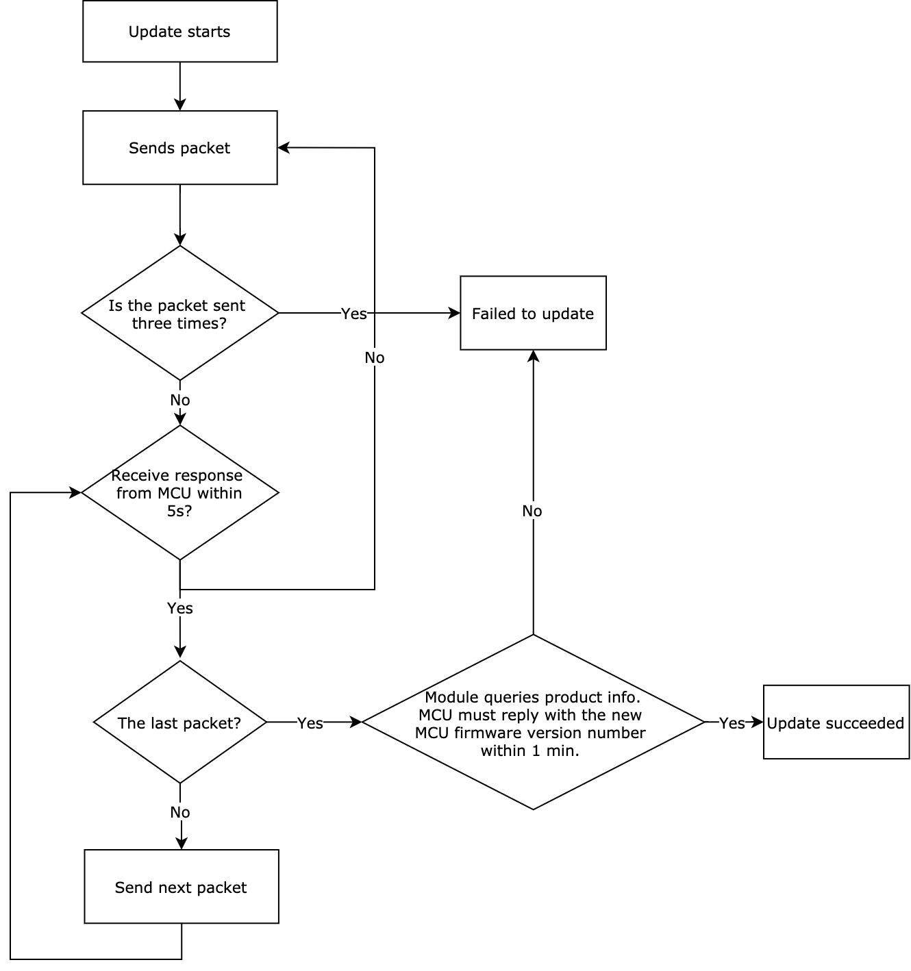
After the Wi-Fi module completes the update transmission, it will send the MCU the command 0x01 to request the product information. The MCU must reply with the software version number and the new MCU software version number within one minute. The new version number should be consistent with that configured on the Developer Platform.
-
The update options:
- Update notification: Users receive a firmware update notification on the app and choose whether to install updates.
- Forced update: Users receive a firmware update notification on the app and have no option but to update the firmware.
- Check for updates: Users will not receive a firmware update notification on the app but need to manually check for new updates.
-
Automatic update (previously named silent update): Users will not receive any update notification. The module checks for firmware updates within the specified time period (for example, one minute) after power on and install updates if any are available. The module checks for updates every 24 hours after the first-time power on.
-
The following flowchart shows how the OTA firmware update works.
Initiate an update
The module sends the following data.
| Field | Length (byte) | Description |
|---|---|---|
| Header | 2 | 0x55aa |
| Version | 1 | 0x00 |
| Command | 1 | 0x1D |
| Data length | 2 | 0x0004 |
| Data | 4 | The size of the update, in big-endian format. |
| Checksum | 1 | Start from the header, add up all the bytes, and then divide the sum by 256 to get the remainder. |
The MCU returns the following data.
| Field | Length (byte) | Description |
|---|---|---|
| Header | 2 | 0x55aa |
| Version | 1 | 0x00 |
| Command | 1 | 0x1D |
| Data length | 2 | 0x0001 |
| Data | 1 | The options for the maximum size of each packet:
|
| Checksum | 1 | Start from the header, add up all the bytes, and then divide the sum by 256 to get the remainder. |
Transfer update package
- Data format: packet offset (unsigned short) + payload data.
- When the MCU receives a frame with a length of four bytes and the fragment offset is equal to or greater than the size of the firmware update, the transfer is completed.
The module sends the following data.
| Field | Length (byte) | Description |
|---|---|---|
| Header | 2 | 0x55aa |
| Version | 1 | 0x00 |
| Command | 1 | 0x1E |
| Data length | 2 | 0x0004+m m: the offset in bytes. |
| Data | offset_addr(4byte) + pack(mbyte) | offset_addr: the offset address.pack: the payload. |
| Checksum | 1 | Start from the header, add up all the bytes, and then divide the sum by 256 to get the remainder. |
Assume that the size of the update is 530 bytes. The MCU does not need to respond to the last packet.
-
For the first packet, the packet offset is
0x00000000, and the packet length is 256 bytes.0x55aa 00 1e 0104 00000000 xx…xx XX -
For the second packet, the packet offset is
0x00000100, and the packet length is 256 bytes.0x55aa 00 1e 0104 00000100 xx…xx XX -
For the third packet, the packet offset is
0x00000200, and the packet length is 18 bytes.0x55aa 00 1e 0016 00000200 xx…xx XX -
For the last packet, the packet offset is
0x00000212, and the packet length is 0 bytes.0x55aa 00 1e 0004 00000212 XX
The MCU returns the following data.
| Field | Length (byte) | Description |
|---|---|---|
| Header | 2 | 0x55aa |
| Version | 1 | 0x00 |
| Command | 1 | 0x1E |
| Data length | 2 | 0x0000 |
| Data | 0 | None |
| Checksum | 1 | Start from the header, add up all the bytes, and then divide the sum by 256 to get the remainder. |
Initiate sub-device update
The module sends the following data.
| Field | Length (byte) | Description |
|---|---|---|
| Header | 2 | 0x55aa |
| Version | 1 | 0x00 |
| Command | 1 | 0x1F |
| Data length | 2 | N |
| Data | N |
|
| Checksum | 1 | Start from the header, add up all the bytes, and then divide the sum by 256 to get the remainder. |
The MCU returns the following data.
| Field | Length (byte) | Description |
|---|---|---|
| Header | 2 | 0x55aa |
| Version | 1 | 0x00 |
| Command | 1 | 0x1F |
| Data length | 2 | 0x0001 |
| Data | 1 | The options for the maximum size of each packet:
|
| Checksum | 1 | Start from the header, add up all the bytes, and then divide the sum by 256 to get the remainder. |
Transfer the update
- Data format: packet offset (unsigned short) + payload data.
- When the MCU receives a frame with a length of four bytes and the fragment offset is equal to or greater than the size of the firmware update, the transfer is completed.
The module sends the following data.
| Field | Length (byte) | Description |
|---|---|---|
| Header | 2 | 0x55aa |
| Version | 1 | 0x00 |
| Command | 1 | 0x20 |
| Data length | 2 | N |
| Data | N |
|
| Checksum | 1 | Start from the header, add up all the bytes, and then divide the sum by 256 to get the remainder. |
Assume that the sub_id is 1234 and the size of the update is 530 bytes. The MCU does not need to respond to the last packet.
-
For the first packet, the packet offset is
0x00000000, and the packet length is 256 bytes.0x55aa 00 20 0109 04 31 32 33 34 00000000 xx…xx XX -
For the second packet, the packet offset is
0x00000100, and the packet length is 256 bytes.0x55aa 00 20 0109 04 31 32 33 34 00000100 xx…xx XX -
For the third packet, the packet offset is
0x00000200, and the packet length is 18 bytes.0x55aa 00 20 001B 04 31 32 33 34 00000200 xx…xx XX -
For the last packet, the packet offset is
0x00000212, and the packet length is 0 bytes.0x55aa 00 20 0009 04 31 32 33 34 00000212 XX
The MCU returns the following data.
| Field | Length (byte) | Description |
|---|---|---|
| Header | 2 | 0x55aa |
| Version | 1 | 0x00 |
| Command | 1 | 0x20 |
| Data length | 2 | 0x0000 |
| Data | 0 | None |
| Checksum | 1 | Start from the header, add up all the bytes, and then divide the sum by 256 to get the remainder. |
Query the version number of the sub-device
The module sends the following data.
| Field | Length (byte) | Description |
|---|---|---|
| Header | 2 | 0x55aa |
| Version | 1 | 0x00 |
| Command | 1 | 0x21 |
| Data length | 2 | N |
| Data | N |
|
| Checksum | 1 | Start from the header, add up all the bytes, and then divide the sum by 256 to get the remainder. |
The MCU returns the following data.
| Field | Length (byte) | Description |
|---|---|---|
| Header | 2 | 0x55aa |
| Version | 1 | 0x00 |
| Command | 1 | 0x21 |
| Data length | 2 | N |
| Data | N |
|
| Checksum | 1 | Start from the header, add up all the bytes, and then divide the sum by 256 to get the remainder. |
Send group control commands (with sub_id)
The following table lists the data format of DP commands.
| Data segment | Length (byte) | Description |
|---|---|---|
| dpid | 1 | The identifier of a DP (DP ID). |
| type | 1 | It indicates the data type of a DP defined on the Tuya Developer Platform.
|
| len | 2 | The length is the number of bytes of the value, in big-endian format. |
| value | 1/2/4/N | Represented in hexadecimal format. Data greater than one byte is transmitted in big-endian format. |
The module sends the following data.
| Field | Length (byte) | Description |
|---|---|---|
| Header | 2 | 0x55aa |
| Version | 1 | 0x00 |
| Command | 1 | 0x22 |
| Data length | 2 | N |
| Data | N |
|
| Checksum | 1 | Start from the header, add up all the bytes, and then divide the sum by 256 to get the remainder. |
The MCU returns the following data.
| Field | Length (byte) | Description |
|---|---|---|
| Header | 2 | 0x55aa |
| Version | 1 | 0x00 |
| Command | 1 | 0x22 |
| Data length | 2 | 0x0000 |
| Data | 0 | None |
| Checksum | 1 | Start from the header, add up all the bytes, and then divide the sum by 256 to get the remainder. |
Query the status of DPs
The module sends the following data.
| Field | Length (byte) | Description |
|---|---|---|
| Header | 2 | 0x55aa |
| Version | 1 | 0x00 |
| Command | 1 | 0x29 |
| Data length | 2 | N |
| Data | N |
|
| Checksum | 1 | Start from the header, add up all the bytes, and then divide the sum by 256 to get the remainder. |
The MCU returns status by using the status reporting command.
Update the connection status of sub-devices
The MCU sends the following data.
| Field | Length (byte) | Description |
|---|---|---|
| Header | 2 | 0x55aa |
| Version | 1 | 0x00 |
| Command | 1 | 0x2A |
| Data length | 2 | N |
| Data | N |
|
| Checksum | 1 | Start from the header, add up all the bytes, and then divide the sum by 256 to get the remainder. |
The module returns the following data.
| Field | Length (byte) | Description |
|---|---|---|
| Header | 2 | 0x55aa |
| Version | 1 | 0x00 |
| Command | 1 | 0x2A |
| Data length | 2 | 0x0001 |
| Data | 1 |
|
| Checksum | 1 | Start from the header, add up all the bytes, and then divide the sum by 256 to get the remainder. |
Get the MAC address of the module
The module returns the MAC address of the wireless network interface.
The MCU sends the following data.
| Field | Length (byte) | Description |
|---|---|---|
| Header | 2 | 0x55aa |
| Version | 1 | 0x00 |
| Command | 1 | 0x2B |
| Data length | 2 | 0x0000 |
| Data | 0 | None |
| Checksum | 1 | Start from the header, add up all the bytes, and then divide the sum by 256 to get the remainder. |
The module returns the following data.
| Field | Length (byte) | Description |
|---|---|---|
| Header | 2 | 0x55aa |
| Version | 1 | 0x00 |
| Command | 1 | 0x2B |
| Data length | 2 | 0x0007 |
| Data | 7 |
|
| Checksum | 1 | Start from the header, add up all the bytes, and then divide the sum by 256 to get the remainder. |
Report the status of time-dependent DPs
- For time-dependent sub-devices such as door locks, the MCU must have the timestamp when an event occurred contained in the payload when it reports status to the module.
- This is a synchronous command. The MCU reports DP status and then waits for the result from the module.
The following table lists the data format of DP commands.
| Data segment | Length (byte) | Description |
|---|---|---|
| dpid | 1 | The identifier of a DP (DP ID). |
| type | 1 | It indicates the data type of a DP defined on the Tuya Developer Platform.
|
| len | 2 | The length is the number of bytes of the value, in big-endian format. |
| value | 1/2/4/N | Represented in hexadecimal format. Data greater than one byte is transmitted in big-endian format. |
The MCU sends the following data.
| Field | Length (byte) | Description |
|---|---|---|
| Header | 2 | 0x55aa |
| Version | 1 | 0x00 |
| Command | 1 | 0x2C |
| Data length | 2 | 7 + N |
| Time | 7 |
|
| Data | N |
|
| Checksum | 1 | Start from the header, add up all the bytes, and then divide the sum by 256 to get the remainder. |
The module returns the following data.
| Field | Length (byte) | Description |
|---|---|---|
| Header | 2 | 0x55aa |
| Version | 1 | 0x00 |
| Command | 1 | 0x2C |
| Data length | 2 | 0x0001 |
| Data | 1 |
|
| Checksum | 1 | Start from the header, add up all the bytes, and then divide the sum by 256 to get the remainder. |
Query the binding status of sub-devices
The MCU sends the following data.
| Field | Length (byte) | Description |
|---|---|---|
| Header | 2 | 0x55aa |
| Version | 1 | 0x00 |
| Command | 1 | 0x2D |
| Data length | 2 | N |
| Data | N |
|
| Checksum | 1 | Start from the header, add up all the bytes, and then divide the sum by 256 to get the remainder. |
The module returns the following data.
| Field | Length (byte) | Description |
|---|---|---|
| Header | 2 | 0x55aa |
| Version | 1 | 0x00 |
| Command | 1 | 0x2D |
| Data length | 2 | N |
| Data | N |
|
| Checksum | 1 | Start from the header, add up all the bytes, and then divide the sum by 256 to get the remainder. |
Query the information of sub-devices in a group
The MCU sends the following data.
| Field | Length (byte) | Description |
|---|---|---|
| Header | 2 | 0x55aa |
| Version | 1 | 0x00 |
| Command | 1 | 0x2E |
| Data length | 2 | N |
| Data | N |
|
| Checksum | 1 | Start from the header, add up all the bytes, and then divide the sum by 256 to get the remainder. |
The module returns the following data.
| Field | Length (byte) | Description |
|---|---|---|
| Header | 2 | 0x55aa |
| Version | 1 | 0x00 |
| Command | 1 | 0x2E |
| Data length | 2 | N |
| Data | N | Example: {"gid":"xxx","sub_id":"xxxx" } |
| Checksum | 1 | Start from the header, add up all the bytes, and then divide the sum by 256 to get the remainder. |
Report the status-updated DP in a group
The MCU sends the following data.
| Field | Length (byte) | Description |
|---|---|---|
| Header | 2 | 0x55aa |
| Version | 1 | 0x00 |
| Command | 1 | 0x2F |
| Data length | 2 | N |
| Data | N |
|
| Checksum | 1 | Start from the header, add up all the bytes, and then divide the sum by 256 to get the remainder. |
The module returns the following data.
| Field | Length (byte) | Description |
|---|---|---|
| Header | 2 | 0x55aa |
| Version | 1 | 0x00 |
| Command | 1 | 0x2F |
| Data length | 2 | 0x0001 |
| Data | 1 |
|
| Checksum | 1 | Start from the header, add up all the bytes, and then divide the sum by 256 to get the remainder. |
Extended features
Weather service
- The weather service feature can be used to get weather information on the device pairing address or home address. If you want to get the weather information of your home address, you need to add the request parameter
w.a.new, and request the real-time weather and forecast weather separately. If you request both simultaneously, only the forecast weather will be returned. - The MCU can proactively get the weather information and enable the module to update the weather information regularly.
- If the return parameters are less than the request parameters, check whether the request parameter name is correct or supported.
- For more information about the weather service data, see Appendix 1.
- For more information about the city service data, see Appendix 2.
- For more information about data types of the weather forecast service, see Appendix 3.
- For more information about weather data in UTF-8 encoding, see Appendix 4.
- For more information about the wind direction code, see Appendix 5.
Enable regular requests of weather data
The MCU sends the following data.
| Field | Length (byte) | Description |
|---|---|---|
| Header | 2 | 0x55aa |
| Version | 1 | 0x00 |
| Command | 1 | 0x33 |
| Data length | 2 | (1+1+(L+K)+(L+K)…) |
| Data | N |
|
| Checksum | 1 | Start from the header, add up all the bytes, and then divide the sum by 256 to get the remainder. |
Example: 55 AA 00 33 00 09 00 1E 06 77 2E 74 65 6D 70 BA
The module returns the following data.
| Field | Length (byte) | Description |
|---|---|---|
| Header | 2 | 0x55aa |
| Version | 1 | 0x00 |
| Command | 1 | 0x33 |
| Data length | 2 | 0x0002 |
| Data | 2 |
|
| Checksum | 1 | Start from the header, add up all the bytes, and then divide the sum by 256 to get the remainder. |
Send weather data
With the regular update of weather data enabled, the module will regularly send weather data to the MCU. After the regular update is successfully enabled, the data will be sent immediately, and then sent at the set interval.
The module sends the following data.
| Field | Length (byte) | Description |
|---|---|---|
| Header | 2 | 0x55aa |
| Version | 1 | 0x00 |
| Command | 1 | 0x33 |
| Data length | 2 | (1+1+(LKTLV)+(LKTLV)+…) or 0x0003 |
| Data | N |
|
| Checksum | 1 | Start from the header, add up all the bytes, and then divide the sum by 256 to get the remainder. |
Example: 55 AA 00 33 00 0F 01 01 06 77 2E 74 65 6D 70 00 04 00 00 00 06 AE
The MCU returns the following data.
| Field | Length (byte) | Description |
|---|---|---|
| Header | 2 | 0x55aa |
| Version | 1 | 0x00 |
| Command | 1 | 0x33 |
| Data length | 2 | 0x0001 |
| Data | 1 | Subcommand: 0x01 |
| Checksum | 1 | Start from the header, add up all the bytes, and then divide the sum by 256 to get the remainder. |
Proactively request weather data
The module only uses this command to confirm a request and sends weather data still through the command 0x3301.
The MCU sends the following data.
| Field | Length | Description |
|---|---|---|
| Header | 2 | 0x55aa |
| Version | 1 | 0x00 |
| Command | 1 | 0x33 |
| Data length | 2 | (1+(L+K)+(L+K)…) |
| Data | N |
|
| Checksum | 1 | Start from the header, add up all the bytes, and then divide the sum by 256 to get the remainder. |
Example: 55 AA 00 33 00 08 02 06 77 2E 74 65 6D 70 9D
The module returns the following data.
| Field | Length (byte) | Description |
|---|---|---|
| Header | 2 | 0x55aa |
| Version | 1 | 0x00 |
| Command | 1 | 0x33 |
| Data length | 2 | 0x0002 |
| Data | 1 | Subcommand: 0x02 |
| 1 | The returned result.0x00: success0x01: failure |
|
| Checksum | 1 | Start from the header, add up all the bytes, and then divide the sum by 256 to get the remainder. |
Examples of weather data requests
The following examples use devices in mainland China.
Request the real-time data of the current day
-
The MCU sends the request:
{"w.temp","w.humidity"}or{"w.temp","w.humidity","w.currdate"}. -
The module returns the following data.
{
    "w.temp":13,
    "w.humidity":100
}
Request the weather forecast of the current day only
The returned result is forecast data. When using, distinguish the forecast data of the day from the real-time data.
-
The MCU sends the request:
{"w.humidity","w.date.1"}. -
The module returns the following data.
{
    "w.humidity.0":100
}
Request daily forecasts
-
The MCU sends the request:
{"w.humidity","w.date.3"}. -
The module returns the following data.
{
    "w.humidity.0":100,
    "w.humidity.1":100,
    "w.humidity.2":100
}
Request weather data with sunset and sunrise time
-
GMT (taking UTC +8 time zone as an example)
-
The MCU sends the request:
{ "w.humidity","w.sunrise","w.sunset","t.unix","w.date.3" }. -
The module returns the following data.
{
    "w.humidity.0":100,
    "w.sunrise.0":"2019-12-27 00:05",
    "w.sunset.0":"2019-12-27 10:54",
    "w.humidity.1":100,
    "w.sunrise.1":"2019-12-28 00:05",
    "w.sunset.1":"2019-12-28 10:54",
    "w.humidity.2":100,
    "w.sunrise.2":"2019-12-29 00:05",
    "w.sunset.2":"2019-12-29 10:54"
}
-
-
Local time (taking UTC +8 time zone as an example)
-
The MCU sends the request:
{ "w.humidity","w.sunrise","w.sunset","t.local","w.date.3" }. -
The module returns the following data.
{
    "w.humidity.0":100,
    "w.sunrise.0":"2019-12-27 08:05",
    "w.sunset.0":"2019-12-27 18:54",
    "w.humidity.1":100,
    "w.sunrise.1":"2019-12-28 08:05",
    "w.sunset.1":"2019-12-28 18:54",
    "w.humidity.2":100,
    "w.sunrise.2":"2019-12-29 08:05",
    "w.sunset.2":"2019-12-29 18:54"
}
-
Request daily forecasts and measured air data
-
The MCU sends the request:
{ "w.temp","w.humidity","w.pm10","w.pm25","w.date.3" }. -
The module returns the following data.
{
    "w.pm10.0":14,
    "w.pm25.0":7,
    "w.humidity.0":100,
    "w.humidity.1":100,
    "w.humidity.2":100
}
If the value
nyou specified for the parameterw.date.nis greater than 7 or not greater than 0, the server takes it as an input parameter error and returns nothing.
Restart a gateway locally
The MCU instructs the module to restart.
The MCU sends the following data.
| Field | Length (byte) | Description |
|---|---|---|
| Header | 2 | 0x55aa |
| Version | 1 | 0x00 |
| Command | 1 | 0x34 |
| Data length | 2 | 0x0001 |
| Data | 1 | Subcommand: 0x09 |
| Checksum | 1 | Start from the header, add up all the bytes, and then divide the sum by 256 to get the remainder. |
The module returns the following data.
| Field | Length (byte) | Description |
|---|---|---|
| Header | 2 | 0x55aa |
| Version | 1 | 0x00 |
| Command | 1 | 0x34 |
| Data length | 2 | 0x0002 |
| Data | 2 |
|
| Checksum | 1 | Start from the header, add up all the bytes, and then divide the sum by 256 to get the remainder. |
Turn on/off 4G feature locally
This command only applies to modules that support 4G network.
The MCU sends the following data.
| Field | Length (byte) | Description |
|---|---|---|
| Header | 2 | 0x55aa |
| Version | 1 | 0x00 |
| Command | 1 | 0x72 |
| Data length | 2 | 0x0002 |
| Data | 2 |
|
| Checksum | 1 | Start from the header, add up all the bytes, and then divide the sum by 256 to get the remainder. |
The module returns the following data.
| Field | Length (byte) | Description |
|---|---|---|
| Header | 2 | 0x55aa |
| Version | 1 | 0x00 |
| Command | 1 | 0x72 |
| Data length | 2 | 0x0002 |
| Data | 2 |
|
| Checksum | 1 | Start from the header, add up all the bytes, and then divide the sum by 256 to get the remainder. |
Report network status of multi-NIC devices
- The device supports multiple network connection methods. In the command
0x01-query product information, Bit1 of the fieldais enabled. - When the network status of the multi-NIC device changes, the module will proactively send its current status to the MCU.
The module sends the following data.
| Field | Length (byte) | Description |
|---|---|---|
| Header | 2 | 0x55aa |
| Version | 1 | 0x00 |
| Command | 1 | 0x72 |
| Data length | 2 | 0x0003 |
| Data | 3 |
|
| Checksum | 1 | Start from the header, add up all the bytes, and then divide the sum by 256 to get the remainder. |
The MCU returns the following data.
| Field | Length (byte) | Description |
|---|---|---|
| Header | 2 | 0x55aa |
| Version | 1 | 0x00 |
| Command | 1 | 0x72 |
| Data length | 2 | 0x0001 |
| Data | 1 | Subcommand: 0x02 |
| Checksum | 1 | Start from the header, add up all the bytes, and then divide the sum by 256 to get the remainder. |
Request network status of multi-NIC devices
The device supports multiple network connection methods. In the command 0x01-query product information, Bit1 of the field a is enabled.
The MCU sends the following data.
| Field | Length (byte) | Description |
|---|---|---|
| Header | 2 | 0x55aa |
| Version | 1 | 0x00 |
| Command | 1 | 0x72 |
| Data length | 2 | 0x0001 |
| Data | 1 | Subcommand: 0x03 |
| Checksum | 1 | Start from the header, add up all the bytes, and then divide the sum by 256 to get the remainder. |
The module returns the following data.
| Field | Length (byte) | Description |
|---|---|---|
| Header | 2 | 0x55aa |
| Version | 1 | 0x00 |
| Command | 1 | 0x72 |
| Data length | 2 | 0x0003 |
| Data | 3 |
|
| Checksum | 1 | Start from the header, add up all the bytes, and then divide the sum by 256 to get the remainder. |
Request IPV4 network details
The MCU sends the following data.
| Field | Length (byte) | Description |
|---|---|---|
| Header | 2 | 0x55aa |
| Version | 1 | 0x00 |
| Command | 1 | 0x72 |
| Data length | 2 | 0x0002 |
| Data | 2 |
|
| Checksum | 1 | Start from the header, add up all the bytes, and then divide the sum by 256 to get the remainder. |
The module returns the following data.
| Field | Length (byte) | Description |
|---|---|---|
| Header | 2 | 0x55aa |
| Version | 1 | 0x00 |
| Command | 1 | 0x72 |
| Data length | 2 | 0x0002 or 0x0013 |
| Data | 2 or 19 |
|
| Checksum | 1 | Start from the header, add up all the bytes, and then divide the sum by 256 to get the remainder. |
Query signal strength of sub-devices
The panel displays the network topology of the sub-devices. When there is a relay sub-device, the MCU will return the IDs and signal strength of the terminal sub-device and the relay sub-device in sequence.
The module sends the following data.
| Field | Length (byte) | Description |
|---|---|---|
| Header | 2 | 0x55aa |
| Version | 1 | 0x00 |
| Command | 1 | 0x72 |
| Data length | 2 | 1 + N |
| Data | 1 | Subcommand: 0x05 |
| N |
|
|
| Checksum | 1 | Start from the header, add up all the bytes, and then divide the sum by 256 to get the remainder. |
The MCU returns the following data.
| Field | Length (byte) | Description |
|---|---|---|
| Header | 2 | 0x55aa |
| Version | 1 | 0x00 |
| Command | 1 | 0x72 |
| Data length | 2 | 1 + N |
| Data | 1 | Subcommand: 0x05 |
| N |
the array elements returned by the MCU have filled in the following order: [ {"sub_id":"sub-device A’s ID","rssi":sub-device A’s rssi}, {"sub_id":"sub-device B’s ID","rssi":sub-device B’s rssi}, {"sub_id":"sub-device C’s ID","rssi":sub-device C’s rssi}, … ] |
|
| Checksum | 1 | Start from the header, add up all the bytes, and then divide the sum by 256 to get the remainder. |
Extended protocol for security features
This section describes the commands specific to the security feature. For more information about implementing the feature, see Security Gateway MCU Development.
Set the arm mode
This command is used to arm or disarm the security system.
- If the system is being armed, to edit the arm mode, you need to disarm the system first.
- The arm delay set by using this command is not valid. You need to set its value to
0. The arm delay setup on the mobile app prevails. sub_id:NULLmeans the gateway itself.
The MCU sends the following data.
| Field | Length (byte) | Description |
|---|---|---|
| Header | 2 | 0x55aa |
| Version | 1 | 0x00 |
| Command | 1 | 0xC0 |
| Data length | 2 | 1 + N |
| Data | 1 | Subcommand: 0x00 |
| N |
|
|
| Checksum | 1 | Start from the header, add up all the bytes, and then divide the sum by 256 to get the remainder. |
The module returns the following data.
| Field | Length (byte) | Description |
|---|---|---|
| Header | 2 | 0x55aa |
| Version | 1 | 0x00 |
| Command | 1 | 0xC0 |
| Data length | 2 | 0x0002 |
| Data | 2 |
|
| Checksum | 1 | Start from the header, add up all the bytes, and then divide the sum by 256 to get the remainder. |
Request the current security status
The MCU sends this command to get the current status of the security system.
The MCU sends the following data.
| Field | Length (byte) | Description |
|---|---|---|
| Header | 2 | 0x55aa |
| Version | 1 | 0x00 |
| Command | 1 | 0xC0 |
| Data length | 2 | 0x0001 |
| Data | 1 | Subcommand: 0x01 |
| Checksum | 1 | Start from the header, add up all the bytes, and then divide the sum by 256 to get the remainder. |
The module returns the following data.
| Field | Length (byte) | Description |
|---|---|---|
| Header | 2 | 0x55aa |
| Version | 1 | 0x00 |
| Command | 1 | 0xC0 |
| Data length | 2 | 1 + N |
| Data | 1 | Subcommand: 0x01 |
| N |
|
|
| Checksum | 1 | Start from the header, add up all the bytes, and then divide the sum by 256 to get the remainder. |
Sync the security mode settings
After receiving the security mode settings from the mobile app, the module uses this command to sync the information with the MCU.
The module sends the following data.
| Field | Length (byte) | Description |
|---|---|---|
| Header | 2 | 0x55aa |
| Version | 1 | 0x00 |
| Command | 1 | 0xC0 |
| Data length | 2 | 1 + N |
| Data | 1 | Subcommand: 0x02 |
| N |
|
|
| Checksum | 1 | Start from the header, add up all the bytes, and then divide the sum by 256 to get the remainder. |
The MCU returns the following data.
| Field | Length (byte) | Description |
|---|---|---|
| Header | 2 | 0x55aa |
| Version | 1 | 0x00 |
| Command | 1 | 0xC0 |
| Data length | 2 | 0x0001 |
| Data | 1 | Subcommand: 0x02 |
| Checksum | 1 | Start from the header, add up all the bytes, and then divide the sum by 256 to get the remainder. |
Sync security events
After receiving a disarming event, the module should notify the MCU to cancel the alarm through the DP 32. You need to set the alarm status.
The module syncs the security events with the MCU by using this command.
The module sends the following data.
| Field | Length (byte) | Description |
|---|---|---|
| Header | 2 | 0x55aa |
| Version | 1 | 0x00 |
| Command | 1 | 0xC0 |
| Data length | 2 | 1 + N |
| Data | 1 | Subcommand: 0x03 |
| N |
|
|
| Checksum | 1 | Start from the header, add up all the bytes, and then divide the sum by 256 to get the remainder. |
The MCU returns the following data.
| Field | Length (byte) | Description |
|---|---|---|
| Header | 2 | 0x55aa |
| Version | 1 | 0x00 |
| Command | 1 | 0xC0 |
| Data length | 2 | 0x0001 |
| Data | 1 | Subcommand: 0x03 |
| Checksum | 1 | Start from the header, add up all the bytes, and then divide the sum by 256 to get the remainder. |
Set alarm status
The alarm delay is set by using the mobile app. After the countdown is done, the module should send the alarm status to the app. If the alarm status is not set, the cloud will also send a message to the app because of the fault tolerance mechanism. We recommend you set the alarm status.
The MCU syncs the alarm status with the module through the DP 32.
The MCU sends the following data.
| Field | Length (byte) | Description |
|---|---|---|
| Header | 2 | 0x55aa |
| Version | 1 | 0x00 |
| Command | 1 | 0xC1 |
| Data length | 2 | 0x0002 |
| Data | 2 |
|
| Checksum | 1 | Start from the header, add up all the bytes, and then divide the sum by 256 to get the remainder. |
The module returns the following data.
| Field | Length (byte) | Description |
|---|---|---|
| Header | 2 | 0x55aa |
| Version | 1 | 0x00 |
| Command | 1 | 0xC1 |
| Data length | 2 | 0x0002 |
| Data | 2 |
|
| Checksum | 1 | Start from the header, add up all the bytes, and then divide the sum by 256 to get the remainder. |
Sync the alarm delay status
When alarm delay is running, the module syncs the current alarm status to the MCU.
The module sends the following data.
| Field | Length (byte) | Description |
|---|---|---|
| Header | 2 | 0x55aa |
| Version | 1 | 0x00 |
| Command | 1 | 0xC1 |
| Data length | 2 | 0x0002 |
| Data | 2 |
|
| Checksum | 1 | Start from the header, add up all the bytes, and then divide the sum by 256 to get the remainder. |
The MCU returns the following data.
| Field | Length (byte) | Description |
|---|---|---|
| Header | 2 | 0x55aa |
| Version | 1 | 0x00 |
| Command | 1 | 0xC1 |
| Data length | 2 | 0x0001 |
| Data | 1 | Subcommand: 0x03 |
| Checksum | 1 | Start from the header, add up all the bytes, and then divide the sum by 256 to get the remainder. |
Sync alarm information (new)
This is a new command used to sync alarm information. It works with bit0 of the a field in the 0x01 command. If bit0 is enabled, processing 0xc101 and 0xc102 is not necessary.
- The
GPfield is not supported. - Non-environmental sensing devices: indicates devices that are not used to sense and monitor the environment.
- Environmental sensing devices: indicates devices that can sense and monitor the environment.
- The payload content depends on the enabled features.
The gp field is reserved for the feature of multi-protection areas. The MCU does not return the value of this field.
The module sends the following data.
| Field | Length (byte) | Description |
|---|---|---|
| Header | 2 | 0x55aa |
| Version | 1 | 0x00 |
| Command | 1 | 0xC1 |
| Data length | 2 | 1 + N |
| Data | 1 | Subcommand: 0x04 |
| N |
|
|
| Checksum | 1 | Start from the header, add up all the bytes, and then divide the sum by 256 to get the remainder. |
The MCU returns the following data.
| Field | Length (byte) | Description |
|---|---|---|
| Header | 2 | 0x55aa |
| Version | 1 | 0x00 |
| Command | 1 | 0xC1 |
| Data length | 2 | 0x0001 |
| Data | 1 | Subcommand: 0x04 |
| Checksum | 1 | Start from the header, add up all the bytes, and then divide the sum by 256 to get the remainder. |
Sync the alarm status (new)
This is a new command used to sync alarm status. It works with the enabled bit0 of the a field in the 0x01 command.
The module sends the following data.
| Field | Length (byte) | Description |
|---|---|---|
| Header | 2 | 0x55aa |
| Version | 1 | 0x00 |
| Command | 1 | 0xC1 |
| Data length | 2 | 0x0002 |
| Data | 1 |
|
| Checksum | 1 | Start from the header, add up all the bytes, and then divide the sum by 256 to get the remainder. |
The MCU returns the following data.
| Field | Length (byte) | Description |
|---|---|---|
| Header | 2 | 0x55aa |
| Version | 1 | 0x00 |
| Command | 1 | 0xC1 |
| Data length | 2 | 0x0001 |
| Data | 1 | Subcommand: 0x05 |
| Checksum | 1 | Start from the header, add up all the bytes, and then divide the sum by 256 to get the remainder. |
Appendices
Appendix 1: Weather data in ASCII
| Parameter | Meaning | Mainland China | Other countries/regions | Weather forecast | Length | Hexadecimal value |
|---|---|---|---|---|---|---|
| w.temp | Atmospheric temperature in °C | Supported | Supported | 7-day forecast (except for mainland China) | 6 | 77 2e 74 65 6d 70 |
| w.humidity | Air humidity | Supported | Supported | 7-day forecast | 10 | 77 2e 68 75 6d 69 64 69 74 79 |
| w.conditionNum | Weather condition No. | Supported | Supported | 7-day forecast | 14 | 77 2e 63 6f 6e 64 69 74 69 6f 6e 4e 75 6d |
| w.pressure | Atmospheric pressure in mbar | Supported | Supported | 7-day forecast (except for mainland China) | 10 | 77 2e 70 72 65 73 73 75 72 65 |
| w.realFeel | Apparent temperature | Supported | Supported | N/A | 10 | 77 2e 72 65 61 6c 46 65 65 6c |
| w.uvi | Ultraviolet index | Supported | Supported | 7-day forecast | 5 | 77 2e 75 76 69 |
| w.sunrise | Sunrise | Supported | Supported | 7-day forecast | 9 | 77 2e 73 75 6e 72 69 73 65 |
| w.sunset | Sunset | Supported | Supported | 7-day forecast | 8 | 77 2e 73 75 6e 73 65 74 |
| t.unix | GMT, used with sunrise (w.sunrise) and sunset (w.sunset) |
- | - | - | 6 | 74 2e 75 6e 69 78 |
| t.local | Local time, used with sunrise (w.sunrise) and sunset (w.sunset) |
- | - | - | 7 | 74 2e 6c 6f 63 61 6c |
| w.windSpeed | Wind speed in m/s | Supported | Supported | 7-day forecast | 11 | 77 2e 77 69 6e 64 53 70 65 65 64 |
| w.windDir | Wind direction | Supported | Supported | 7-day forecast | 9 | 77 2e 77 69 6e 64 44 69 72 |
| w.windLevel | Wind scale | Mainland China only | Not supported | 7-day forecast | 11 | 77 2e 77 69 6e 64 4c 65 76 65 6c |
| w.aqi | Air quality index, US EPA standard: 0 to 500 | Supported | Supported | Current day only | 5 | 77 2e 61 71 69 |
| w.rank/w.quality | AQI details and national ranking | Mainland China only | Not supported | Current day only | 6 | 77 2e 72 61 6e 6b / 77 2e 71 75 61 6c 69 74 79 |
| w.pm10 | PM10 (inhalable particulate matter) in µg/m³ | Supported | Supported | Current day only | 6 | 77 2e 70 6d 31 30 |
| w.pm25 | PM2.5 (fine particulate matter) in µg/m³ | Supported | Supported | Current day only | 6 | 77 2e 70 6d 32 35 |
| w.o3 | Ozone level in µg/m³ | Supported | Supported | Current day only | 4 | 77 2e 6f 33 |
| w.no2 | Nitrogen dioxide level in µg/m³ | Supported | Supported | Current day only | 5 | 77 2e 6e 6f 32 |
| w.co | Carbon monoxide level in µg/m³ | Supported | Supported | Current day only | 4 | 77 2e 63 6f |
| w.so2 | Sulfur dioxide level in µg/m³ | Supported | Supported | Current day only | 5 | 77 2e 73 6f 32 |
| w.thigh | The highest temperature in °C | Supported | Supported | Forecast only | 7 | 77 2e 74 68 69 67 68 |
| w.tlow | The lowest temperature in °C | Supported | Supported | Forecast only | 6 | 77 2e 74 6c 6f 77 |
| w.date.n | Number of forecast days, represented by n with 1 ≤ n ≤ 7 |
Supported | Supported | - | 8 | 77 2e 64 61 74 65 2e 6e |
| w.currdate | Current weather | Supported | Supported | - | 10 | 77 2e 63 75 72 72 64 61 74 65 |
-
WindDirindicates the wind direction. For more information about the wind direction code, see Appendix 5. -
w.conditionNumindicates the weather condition code. For more information, see Appendix 4. -
Atmospheric pressure conversion:
1 mbar = 100 pa = 1 hPa.
-
Support for forecasts: If
w.date.nis carried, the return data is the weather forecast. -
Support for real-time weather data: For weather requests with
w.date.ncarried,w.currdatecan be carried to get the real-time weather data at the same time. For more information, see Examples of weather data requests.
Appendix 2: City service data in ASCII
| Parameter | Description | Type | Length | Hexadecimal value |
|---|---|---|---|---|
| c.area | County or district name | String | 6 | 63 2e 61 72 65 61 |
| c.city | City name | String | 6 | 63 2e 63 69 74 79 |
| c.province | Province | String | 10 | 63 2e 70 72 6f 76 69 6e 63 65 |
If the weather service API only returns the service city without any content, it indicates the device does not provide its latitude and longitude, so the request failed. To resolve this issue, you should guide users to enable the location on their mobile phone and pair the device with the mobile app again.
Appendix 3: Weather forecast service
| Parameter | Description | Type | Real-time weather | Weather forecast |
|---|---|---|---|---|
| w.temp | Temperature | Integer | Yes | Supported (except for mainland China) |
| w.humidity | Humidity | Integer | Yes | Yes |
| w.conditionNum | Weather condition No. | String | Yes | Yes |
| w.pressure | Air pressure | Integer | Yes | Supported (except for mainland China) |
| w.realFeel | Apparent temperature | Integer | Yes | No |
| w.uvi | Ultraviolet index | Integer | Yes | Yes |
| w.windDir | Wind direction | String | Yes | Yes |
| w.windLevel | Wind scale | Integer | Mainland China only | No |
| w.windSpeed | Wind speed | String (format example: 1.0; 0.5) |
Yes | Yes |
| w.sunrise | Sunrise time | String (format example: 2017-04-24 05:24) | Yes | Yes |
| w.sunset | Sunset time | String (format example: 2017-04-24 18:32) | Yes | Yes |
| w.aqi | Air quality index | Integer | Yes | No |
| w.pm25 | PM2.5 | Integer | Yes | No |
| w.so2 | Sulfur dioxide level | Integer | Yes | No |
| w.rank/w.quality | Air quality rating | String (format example: 447/609) | Mainland China only | No |
| w.pm10 | PM10 | Integer | Yes | No |
| w.o3 | Ozone (O3) level | Integer | Yes | No |
| w.no2 | Nitrogen dioxide (NO2) level | Integer | Yes | No |
| w.co | Carbon monoxide (CO) level | Integer | Yes | No |
| w.qualityLevel | Air quality rating | Integer | Yes | No |
| w.thigh | The highest temperature | Integer | No | Yes |
| w.tlow | The lowest temperature | Integer | No | Yes |
- The number in the string is rounded to one decimal place. Example:
1.0; 0.9. - Support for real-time weather data: For weather requests with
w.date.ncarried,w.currdatecan be carried to get the real-time weather data at the same time. For more information, see Examples of weather data requests. - Support for forecasts: If
w.date.nis carried, the return data is the weather forecast.
Appendix 4: Weather data in UTF-8 encoding
w.conditionNum in ASCII code |
Hexadecimal value | Weather conditions |
|---|---|---|
| 120 | 31 32 30 | Sunny |
| 101 | 31 30 31 | Heavy rain |
| 102 | 31 30 32 | Thunderstorm |
| 103 | 31 30 33 | Sandstorm |
| 104 | 31 30 34 | Light snow |
| 105 | 31 30 35 | Snow |
| 106 | 31 30 36 | Freezing fog |
| 107 | 31 30 37 | Rainstorm |
| 108 | 31 30 38 | Isolated shower |
| 109 | 31 30 39 | Dust |
| 110 | 31 31 30 | Thunder and lightning |
| 111 | 31 31 31 | Light shower |
| 112 | 31 31 32 | Rain |
| 113 | 31 31 33 | Sleet |
| 114 | 31 31 34 | Dust devil |
| 115 | 31 31 35 | Ice pellets |
| 116 | 31 31 36 | Strong sandstorm |
| 117 | 31 31 37 | Sand blowing |
| 118 | 31 31 38 | Light to moderate rain |
| 119 | 31 31 39 | Mostly clear |
| 121 | 31 32 31 | Fog |
| 122 | 31 32 32 | Shower |
| 123 | 31 32 33 | Heavy shower |
| 124 | 31 32 34 | Heavy snow |
| 125 | 31 32 35 | Extreme rainstorm |
| 126 | 31 32 36 | Blizzard |
| 127 | 31 32 37 | Hail |
| 128 | 31 32 38 | Light to moderate snow |
| 129 | 31 32 39 | Partly cloudy |
| 130 | 31 33 30 | Light snow shower |
| 131 | 31 33 31 | Moderate snow |
| 132 | 31 33 32 | Overcast |
| 133 | 31 33 33 | Needle ice |
| 134 | 31 33 34 | Downpour |
| 136 | 31 33 36 | Thundershower and hail |
| 137 | 31 33 37 | Freezing rain |
| 138 | 31 33 38 | Snow shower |
| 139 | 31 33 39 | Light rain |
| 140 | 31 34 30 | Haze |
| 141 | 31 34 31 | Moderate rain |
| 142 | 31 34 32 | Cloudy |
| 143 | 31 34 33 | Thundershower |
| 144 | 31 34 34 | Moderate to heavy rain |
| 145 | 31 34 35 | Heavy rain to rainstorm |
| 146 | 31 34 36 | Clear |
Appendix 5: Wind direction code
| Code (string) | Hexadecimal value | Description |
|---|---|---|
| N | 4e | North |
| NNE | 4e 4e 45 | Northeast by north |
| NE | 4e 45 | Northeast |
| ENE | 45 4e 45 | Northeast by east |
| E | 45 | East |
| ESE | 45 53 45 | Southeast by east |
| SE | 53 45 | Southeast |
| SSE | 53 53 45 | Southeast by south |
| S | 53 | South |
| SSW | 53 53 57 | Southwest by south |
| SW | 53 57 | Southwest |
| WSW | 57 53 57 | Southwest by west |
| W | 57 | West |
| WNW | 57 4e 57 | Northwest by west |
| NW | 4e 57 | Northwest |
| NNW | 4e 4e 57 | Northwest by north |
Is this page helpful?
YesFeedbackIs this page helpful?
YesFeedback


