Basic Features
This topic describes the serial protocol that is used to implement serial communication between Tuya’s Bluetooth module and the third-party MCU, as shown in the following diagram.
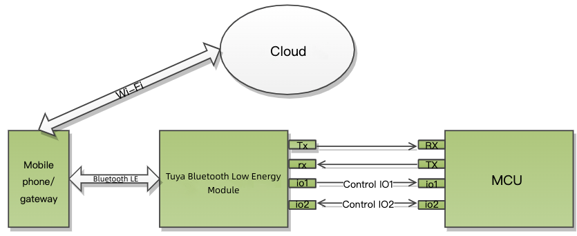
Serial communication convention
-
Baud: 9600/115200 bps
-
Data bit: 8
-
Parity check: none
-
Stop bit: 1
-
Data flow control: none
After the Bluetooth module is powered on or restarted, it will start automatic baud rate detection. The module sends a heartbeat packet to the MCU at the baud rate configured last time. It changes to another baud rate at the next heartbeat interval and so on. If the module receives the correct response from the MCU, it will stop baud rate detection and write the current serial port configuration to the flash memory. Some legacy firmware versions do not support automatic baud rate detection.
Terms
| Term | Description |
|---|---|
| Data point (DP) | A DP is an abstract representation of a product function. For more information, see Product Functions. |
| Product ID (PID) | A PID is an abstract representation of a collection of physical devices that have the same configurations and properties. Each product created on the Tuya Developer Platform is assigned a unique PID that is associated with the product information, including DPs, app control panel, and purchase information. |
| Bind Bluetooth device | Bind a Bluetooth device with an app account through the Tuya-specific Bluetooth protocol to register the device to the cloud. |
| Unbind Bluetooth device | Unbind a Bluetooth device from an app account. The device will be in the unbound and not connected state. |
| Reset Bluetooth device | Unbind a Bluetooth device and clear the user data by using the app. The difference between resetting and unbinding is whether the user data is cleared. |
| Bluetooth connection | Indicate a Bluetooth device is in the connection state in the link layer. |
| Bluetooth advertising | Indicate a Bluetooth device is in the advertising state in the link layer. |
| Bluetooth pairing status | Indicate a Bluetooth device that is not bound and not connected is advertising specified data, allowing the mobile app to discover the advertising device. |
| Bluetooth bound and connected | Indicate a Bluetooth device is online. The device is bound with and establishes a secure connection with the app through the Tuya-specific Bluetooth protocol. |
| Bluetooth bound but not connected | Indicate a Bluetooth device is offline. The device is bound with but not connected to the app. |
| Bluetooth gateway online | The gateway connection status depends on the logic to determine the online/offline status, which can vary depending on the gateway for use.
|
Packet structure
| No. | Bytes | Field | Description |
|---|---|---|---|
| 0 1 |
2 | Header | 0x55 0xAA |
| 2 | 1 | Version number | It is used for update and extension |
| 3 | 1 | Command (CMD) | Specific frame type |
| 4 5 |
2 | Data length (Len) | Upper 8 bits Lower 8 bits |
| 6 to 6+Len-1 | Len | Data | - |
| 6+Len | 1 | CRC8 | Start from the header, add up all the bytes, and then divide the sum by 256 to get the remainder |
All data greater than one byte is transmitted in big-endian format.
DP format
| Field | Bytes | Description |
|---|---|---|
| dp_id | 1 | The ID of a DP. |
| dp_type | 1 | The data type of a DP. |
| dp_data_len | 2 | The data length of a DP. |
| dp_data_value | dp_data_len | The data of a DP. |
The value range and description of dp_type (cloud defined):
| dp_type | Value | Bytes | Description |
|---|---|---|---|
| raw | 0x00 | 1 to 255 | The raw data in hexadecimal format. |
| bool | 0x01 | 1 | Boolean type. |
| value | 0x02 | 4 | Integer type. |
| string | 0x03 | 0 to 255 | String type. Its value can be empty. |
| enum | 0x04 | 1 | Enumeration type. |
| bitmap | 0x05 | 1/2/4 | Data greater than one byte is transmitted in big-endian format. |
Generic protocol
Heartbeat mechanism (0x00)
-
After power on, the module will send a heartbeat packet to the MCU every 3 seconds. If the MCU correctly responds to a heartbeat, it indicates the MCU works properly. After the first-time heartbeat communication, the module will send the MCU a command to get product information.
-
The MCU can determine whether the module works properly by the regular heartbeat check. If the MCU does not receive a heartbeat packet as expected, it can use the reset pin to reset the module.
-
After getting the MCU information, the module checks the heartbeat every 10 seconds in standard power mode. In low power mode, there is no heartbeat check.
The Telink Bluetooth modules do not perform heartbeat checks both in low power mode. They cannot detect whether the MCU has been restarted.
The module sends the following data.
| No. | Bytes | Field | Description |
|---|---|---|---|
| 0 1 |
2 | Header | 0x55 0xAA |
| 2 | 1 | Version number | 0x00 |
| 3 | 1 | Command (CMD) | 0x00 |
| 4 5 |
2 | Data length | 0x00 0x00 |
| 6 | 1 | CRC8 | Start from the header, add up all the bytes, and then divide the sum by 256 to get the remainder |
The MCU returns the following data.
| No. | Bytes | Field | Description |
|---|---|---|---|
| 0 1 |
2 | Header | 0x55 0xAA |
| 2 | 1 | Version number | 0x00 |
| 3 | 1 | Command (CMD) | 0x00 |
| 4 5 |
2 | Data length | 0x00 0x01 |
| 6 | 1 | State | Return value |
| 7 | 1 | CRC8 | Start from the header, add up all the bytes, and then divide the sum by 256 to get the remainder |
Return value of state:
0x00: The MCU returns this value on the first-time heartbeat communication after a restart. The module uses this value to determine whether the MCU restarts during operation.0x01: The MCU returns this value except for the first response after a restart.``
Get MCU information (0x01)
- Product key: a unique 8-digit identifier assigned to each product created on the platform for storing product information in the cloud.
- Product information: refers to the PID.
- The generic protocol v2.0.0 or later versions allow you to configure firmware features with the optional TLD configuration item. Contact the technical engineer or submit a service ticket for details.
The module sends the following data.
| No. | Bytes | Field | Description |
|---|---|---|---|
| 0 1 |
2 | Header | 0x55 0xAA |
| 2 | 1 | Version number | 0x00 |
| 3 | 1 | Command (CMD) | 0x01 |
| 4 5 |
2 | Data length | 0x00 0x00 |
| 6 | 1 | CRC8 | Start from the header, add up all the bytes, and then divide the sum by 256 to get the remainder |
The MCU returns the following data.
| No. | Bytes | Field | Description |
|---|---|---|---|
| 0 1 |
2 | Header | 0x55 0xAA |
| 2 | 1 | Version number | 0x00 |
| 3 | 1 | Command (CMD) | 0x01 |
| 4 5 |
2 | Data length | 0x00 0x0d |
| 6 to 18+n | 13+n | Data | See the following table |
| 19+n | 1 | CRC8 | Start from the header, add up all the bytes, and then divide the sum by 256 to get the remainder |
Data format
| 1 to 8 | 9 to 13 | 14 to 14+n |
|---|---|---|
| PID | The reserved field. | The optional information TLD [TLD][TLD]… |
Example: 55 AA 00 01 00 0D 66 74 62 38 78 32 78 30 31 2E 30 2E 30 C0, indicating the PID is ftb8x2x0 and the MCU version number is 1.0.0.
-
PID: an 8-digit string, such as
ftb8x2x0. -
Reserved field: populated with the MCU version number as the placeholder by default. The module does not parse this field. The MCU reports its version number using the command
0xE8or0xE9. -
TLD: used to configure the features and capabilities for the generic firmware. TLD refers to a custom data format:
Tis short for Type, indicating the ID of the feature to set.Lis short for Length, indicating the length of the data to set.Dis short for Data, indicating the data to set.
You can set one or multiple TLDs. If you use the default configuration, you can leave this field as is. Otherwise, populate it with the desired content.
The values of
TandLare fixed. The module can get the value ofDby parsing theTandL. There is no order requirement for multiple TLDs.The following table lists the TLD data format. The number refers to the sequence number of the byte.
-
When
Tis0x07andLis0x01,Dindicates the configuration of beacon capability. This is an optional TLD. If you do not choose and set it, beacon is not supported by default.1 2 3 T (0x07) L (0x01) beacon_enable beacon_enable: indicates the beacon capability for status reporting. With beacon enabled, the device in bound but not connected can report status to the gateway or app by using broadcasting. For more information, see Status reporting (0x07).-
0x00: Disable -
0x01: Enable -
Others: reserved
Example: 55 AA 00 01 00 10 6D 6E 75 78 64 38 30 75 31 2E 30 2E 30 07 01 01 0F
-
-
When
Tis0x03andLis0x01,Dindicates the configuration of device online policy. This is an optional TLD. If you do not choose and set it, the default value is0x00.1 2 3 T (0x03) L (0x01) online_flag online_flag: the flag of device online policy. The policy depends on the Bluetooth gateway for use instead of the mobile app.0x00: Use the policy of standard power consumption.0x01: Use the policy of low power consumption.- Others: reserved
Example: 55 AA 00 01 00 13 6D 6E 75 78 64 38 30 75 31 2E 30 2E 30 07 01 01 03 01 01 17
-
When
Tis0xBAandLis0x01,Dindicates the SMP enablement. This is an optional TLD. If you do not choose and set it, the default value is0x00.1 2 3 T (0xBA) L (0x01) SMP_ENABLE SMP_ENABLE: the enablement of Bluetooth SMP feature.0x00: Disable SMP pairing.0x01: Enable SMP pairing.- Others: reserved
Example: 55 AA 00 01 00 10 34 6B 78 36 68 6C 61 78 31 2E 30 2E 30 BA 01 01 B3
-
When T is
0x01and L is0x01, D indicates the configuration of the secure connection type. This is an optional TLD. If you do not choose and set it, the default value is0x00.1 2 3 T (0x01) L (0x01) Secure_connect_type Secure_connect_type: The type of secure Bluetooth connection.0x00: Use the default setting. A Bluetooth device can be added by either scanning QR codes or searching for devices.0x01: A Bluetooth device can be added only by scanning QR codes.- Others: reserved
Example: 55 AA 00 01 00 10 34 6B 78 36 68 6C 61 78 31 2E 30 2E 30 01 01 01 FA
-
When T is
0x02and L is0x01, D indicates the configuration of the connection policy. This is an optional TLD. If you do not choose and set it, the default value is0x00.1 2 3 T (0x02) L (0x01) connection_strategy connection_strategy: Bluetooth connection strategy. After configuration changes, the device needs to be paired again.- Bit 0: Gateway connect mode.
0: Non-persistent connection. You can connect on demand.1: Persistent connection.- The configurations of this bit only apply to the gateway.
- Bit 1 to bit 2: Connectivity.
0: Support both mobile phones and gateways.1: Only support gateways.2: Only support mobile phones.
- All other bits are reserved.
Example: Support persistent connection through gateway: 55 AA 00 01 00 10 34 6B 78 36 68 6C 61 78 31 2E 30 2E 30 02 01 01 FB
- Bit 0: Gateway connect mode.
-
When
Tis0xC2andLis0x01,Dindicates the configuration of accessory support. This is an optional TLD. If you do not choose and set it, the default value is0x00.1 2 3 T (0xC2) L (0x01) Accessory_Support Accessory_Support: Specifies whether to support non-smart accessories. After configuration changes, the device needs to be paired again.0x00: Not supported. It is the default value.0x01: Supported. You can implement activation, DP data transfer, and OTA updates for the accessory. For more information, see the serial protocol for accessories.- Others: Reserved.
Example: 55 AA 00 01 00 10 34 6B 78 36 68 6C 61 78 31 2E 30 2E 30 C2 01 01 BB
The MCU information and configuration are stored in the flash memory. If you do not set the optional information, the module will use the default configuration or the previous configuration if any.
Request working mode (0x02)
-
The working mode indicates how the network status is indicated and the way to trigger module reset. Theoretically, the module can work in the following two modes:
- The MCU works with the module to process network events: The module sends its current work status to the MCU through serial communication. The MCU controls the LED to indicate status accordingly. When the MCU detects a request to reset the module, it directs the module to reset through serial communication.
- The module processes network events itself: Not supported.
-
The Bluetooth module only supports the first collaboration mode.
The module sends the following data.
| No. | Bytes | Field | Description |
|---|---|---|---|
| 0 1 |
2 | Header | 0x55 0xAA |
| 2 | 1 | Version number | 0x00 |
| 3 | 1 | Command (CMD) | 0x02 |
| 4 5 |
2 | Data length | 0x00 0x00 |
| 6 | 1 | CRC8 | Start from the header, add up all the bytes, and then divide the sum by 256 to get the remainder |
Example: 55 aa 00 02 00 00 01
The MCU returns the following data.
| No. | Bytes | Field | Description |
|---|---|---|---|
| 0 1 |
2 | Header | 0x55 0xAA |
| 2 | 1 | Version number | 0x00 |
| 3 | 1 | Command (CMD) | 0x02 |
| 4 5 |
2 | Data length | 0x00 0x00 |
| 6 | 1 | CRC8 | Start from the header, add up all the bytes, and then divide the sum by 256 to get the remainder |
Example: 55 AA 00 02 00 00 01
Send working status (0x03)
- The module’s status:
0x00: Unbound0x01: Bound but not connected0x02: Bound and connected
- The module will send its current status to the MCU after responding to the command
0x02. - The module will send its current state to the MCU when the state changes.
The module sends the following data.
| No. | Bytes | Field | Description |
|---|---|---|---|
| 0 1 |
2 | Header | 0x55 0xAA |
| 2 | 1 | Version number | 0x00 |
| 3 | 1 | Command (CMD) | 0x03 |
| 4 5 |
2 | Data length | 0x00 0x01 |
| 6 | 1 | State | Return value |
| 7 | 1 | CRC8 | Start from the header, add up all the bytes, and then divide the sum by 256 to get the remainder |
| State | Status | Things to note |
|---|---|---|
| 0x00 | Unbound | The shared devices either in the unbound state or bound but not connected state are considered as ready for pairing with the mobile app. |
| 0x01 | Bound but not connected | Same as above. |
| 0x02 | Bound and connected | For shared devices, this state indicates that a device is paired and connected. |
Reset the module (0x04)
-
The MCU sends this command to direct the Bluetooth module to be disconnected and unbound. The module’s cache data will be cleared.
-
The pairing information and business data cache will be cleared, but other configuration information of the module will not be cleared.
If the MCU uses the Bluetooth broadcast enable (
0xA3) interface to turn off the Bluetooth broadcast, or sets the trigger pairing (0xBC), the MCU needs to start the Bluetooth pairing broadcast again through the Bluetooth broadcast enable (0xA3) or trigger pairing (0xBC) interface.
The MCU sends the following data.
| No. | Bytes | Field | Description |
|---|---|---|---|
| 0 1 |
2 | Header | 0x55 0xAA |
| 2 | 1 | Version number | 0x00 |
| 3 | 1 | Command (CMD) | 0x04 |
| 4 5 |
2 | Data length | 0x00 0x00 |
| 6 | 1 | CRC8 | Start from the header, add up all the bytes, and then divide the sum by 256 to get the remainder |
Example: 55 aa 00 04 00 00 03
The module returns the following data.
| No. | Bytes | Field | Description |
|---|---|---|---|
| 0 1 |
2 | Header | 0x55 0xAA |
| 2 | 1 | Version number | 0x00 |
| 3 | 1 | Command (CMD) | 0x04 |
| 4 5 |
2 | Data length | 0x00 0x00 |
| 6 | 1 | CRC8 | Start from the header, add up all the bytes, and then divide the sum by 256 to get the remainder |
Example: 55 AA 00 04 00 00 03
Reset the module (New) (0x05)
-
The MCU sends this command to direct the Bluetooth module to be disconnected and unbound. The module’s cache data will be cleared.
-
This command works the same way as the
0x04. The only difference is this0x05command is used to resolve historical issues. -
The pairing information and business data cache will be cleared, but other configuration information of the module will not be cleared.
If the MCU uses the Bluetooth broadcast enable (
0xA3) interface to turn off the Bluetooth broadcast, or sets the trigger pairing (0xBC), the MCU needs to start the Bluetooth pairing broadcast again through the Bluetooth broadcast enable (0xA3) or trigger pairing (0xBC) interface.
The MCU sends the following data.
| No. | Bytes | Field | Description |
|---|---|---|---|
| 0 1 |
2 | Header | 0x55 0xAA |
| 2 | 1 | Version number | 0x00 |
| 3 | 1 | Command (CMD) | 0x05 |
| 4 5 |
2 | Data length | 0x00 0x00 |
| 6 | 1 | CRC8 | Start from the header, add up all the bytes, and then divide the sum by 256 to get the remainder |
Example: 55 aa 00 05 00 00 04
The module returns the following data.
| No. | Bytes | Field | Description |
|---|---|---|---|
| 0 1 |
2 | Header | 0x55 0xAA |
| 2 | 1 | Version number | 0x00 |
| 3 | 1 | Command (CMD) | 0x05 |
| 4 5 |
2 | Data length | 0x00 0x00 |
| 6 | 1 | CRC8 | Start from the header, add up all the bytes, and then divide the sum by 256 to get the remainder |
Example: 55 AA 00 05 00 00 04
Send commands (0x06)
- For more information about DPs, see DP format.
- One command can contain data units of multiple DPs.
- The command sending is processed asynchronously, corresponding to the MCU reporting status.
The module sends the following data.
| No. | Bytes | Field | Description |
|---|---|---|---|
| 0 1 |
2 | Header | 0x55 0xAA |
| 2 | 1 | Version number | 0x00 |
| 3 | 1 | Command (CMD) | 0x06 |
| 4 5 |
2 | Data length (Len) | Upper 8 bits Lower 8 bits |
| 6 to 6+Len-1 | Len | DP | See the following table |
| 6+Len | 1 | CRC8 | Start from the header, add up all the bytes, and then divide the sum by 256 to get the remainder |
DP format:
| 1 | 2 | 3 to 4 | 5 and followings | … | n | n+1 | n+1 to n+2 | n+3 and followings |
|---|---|---|---|---|---|---|---|---|
| dp1_id | dp1_type | dp1_len | dp1_data | … | dpN_id | dpN_type | dpN_len | dpN_data |
Example: 55 aa 00 06 00 05 03 01 00 01 01 10
The MCU returns the following data.
None.
Report status (0x07)
- For more information about DPs, see DP format.
- A piece of status data can contain data units of multiple DPs.
- This is an asynchronous command. The MCU uses it to report device status to the module, which can be triggered by three mechanisms.
- After the MCU executes the command received from the module, it reports the changed DP status to the module.
- When the MCU proactively detects status changes of DPs, it reports the changed DP status to the module.
- When the MCU receives the DP status query, it sends the status of all DPs to the module.
- If you enable the beacon capability, the module in bound but not connected can report status using advertising. The maximum
dp_lenin each DP is four bytes. For more information about the beacon capability, see Get MCU information (0x01). - The maximum DP data length varies depending on the firmware of different chip platforms. Currently, Telink, BK3431Q, and BK3432 platforms support a maximum length of 220 bytes, while PHY6222 and FR8016 support a maximum length of 512 bytes.
The MCU sends the following data.
| No. | Bytes | Field | Description |
|---|---|---|---|
| 0 1 |
2 | Header | 0x55 0xAA |
| 2 | 1 | Version number | 0x00 |
| 3 | 1 | Command (CMD) | 0x07 |
| 4 5 |
2 | Data length (Len) | Upper 8 bits Lower 8 bits |
| 6 to 6+Len-1 | Len | DP | See the following table |
| 6+Len | 1 | CRC8 | Start from the header, add up all the bytes, and then divide the sum by 256 to get the remainder |
DP format
| 1 | 2 | 3 to 4 | 5 and followings | … | n | n+1 | n+1 to n+2 | n+3 and followings |
|---|---|---|---|---|---|---|---|---|
| dp1_id | dp1_type | dp1_len | dp1_data | … | dpN_id | dpN_type | dpN_len | dpN_data |
Example: 55 aa 00 07 00 05 03 01 00 01 01 11
The module returns the following data.
| No. | Bytes | Field | Description |
|---|---|---|---|
| 0 1 |
2 | Header | 0x55 0xAA |
| 2 | 1 | Version number | 0x00 |
| 3 | 1 | Command (CMD) | 0x07 |
| 4 5 |
2 | Data length | 0x00 0x01 |
| 6 | 1 | State | Return value |
| 7 | 1 | CRC8 | Start from the header, add up all the bytes, and then divide the sum by 256 to get the remainder |
Return value of state:
0x00: Success- Other values: Failure
Query status (0x08)
- The module asynchronously queries the status of all object-type DPs from the MCU. When the MCU receives a query, it reports the status of the respective DP through the command 0x07.
- The module sends a status query to the MCU when the following two events occur.
- For a bound and connected module, it detects that the MCU is restarted based on the heartbeat check.
The Telink generic firmware does not support detecting MCU restart.
- A bound module is reconnected after it goes offline.
- For a bound and connected module, it detects that the MCU is restarted based on the heartbeat check.
The module sends the following data.
| No. | Bytes | Field | Description |
|---|---|---|---|
| 0 1 |
2 | Header | 0x55 0xAA |
| 2 | 1 | Version number | 0x00 |
| 3 | 1 | Command (CMD) | 0x08 |
| 4 5 |
2 | Data length | 0x00 0x00 |
| 6 | 1 | CRC8 | Start from the header, add up all the bytes, and then divide the sum by 256 to get the remainder |
Example: 55 aa 00 08 00 00 07
The MCU returns the following data.
None.
Unbind the module (0x09)
After the MCU sends this command, the Bluetooth module will be disconnected and unbound from the mobile app. Its virtual ID and cache data will not be cleared.
This command does not apply to the generic firmware for the shared devices.
The MCU sends the following data.
| No. | Bytes | Field | Description |
|---|---|---|---|
| 0 1 |
2 | Header | 0x55 0xAA |
| 2 | 1 | Version number | 0x00 |
| 3 | 1 | Command (CMD) | 0x09 |
| 4 5 |
2 | Data length | 0x00 0x00 |
| 6 | 1 | CRC8 | Start from the header, add up all the bytes, and then divide the sum by 256 to get the remainder |
The module returns the following data.
| No. | Bytes | Field | Description |
|---|---|---|---|
| 0 1 |
2 | Header | 0x55 0xAA |
| 2 | 1 | Version number | 0x00 |
| 3 | 1 | Command (CMD) | 0x09 |
| 4 5 |
2 | Data length | 0x00 0x01 |
| 6 | 1 | State | Return value |
| 7 | 1 | CRC8 | Start from the header, add up all the bytes, and then divide the sum by 256 to get the remainder |
Return value of state:
0x00: Success- Other values: Failure
Query the module’s connection status (0x0A)
- The MCU proactively queries the current connection status of the module. The module returns its status through the command 0x03.
- The module’s status:
0x00: Unbound0x01: Bound but not connected0x02: Bound and connected
The MCU sends the following data.
| No. | Bytes | Field | Description |
|---|---|---|---|
| 0 1 |
2 | Header | 0x55 0xAA |
| 2 | 1 | Version number | 0x00 |
| 3 | 1 | Command (CMD) | 0x0A |
| 4 5 |
2 | Data length | 0x00 0x00 |
| 6 | 1 | CRC8 | Start from the header, add up all the bytes, and then divide the sum by 256 to get the remainder |
Flag-based status reporting (0xA4)
- You can use flags to indicate whether to report specific real-time data to the cloud or the app panel.
- In this asynchronous command, the reply will be sent to the MCU after the app replies ACK. Its SN is the SN written by the MCU when reporting the DP. Therefore, the MCU can also use this feature to confirm whether the DP has actually reached the app, and can implement the DP retransmission logic.
The MCU sends the following data.
| No. | Bytes | Field | Description |
|---|---|---|---|
| 0 1 |
2 | Header | 0x55 0xAA |
| 2 | 1 | Version number | 0x00 |
| 3 | 1 | Command (CMD) | 0xA4 |
| 4 5 |
2 | Data length (Len) | Upper 8 bits Lower 8 bits |
| 6 to 6+Len-1 | Len | Data | See the following table |
| 6+Len | 1 | CRC8 | Start from the header, add up all the bytes, and then divide the sum by 256 to get the remainder |
Data format
| 2 bytes | 1 byte | 1 byte | (Optional) 13 bytes | m byte(s) |
|---|---|---|---|---|
| Sequence number (SN) | Flag | Time_flag | Time_date | DP |
-
Sequence number (SN): two bytes in length, in big-endian (high byte first) format.
-
Flag:
0x00: Report data both to the cloud and the app panel.0x01: Report data to the cloud but not to the app panel.0x02: Report data to the app panel but not to the cloud.0x03: Not report data.
-
Time_flag:0x00: Report data with the time data from the module.0x01: Report data with the time data from the MCU.0x02: Report data without including the time data.
-
Time_date: 13-digit Unix timestamp. This field is required whenTime_flagis set to0x01. -
DP data: the payload. For more information, see DP format.
For example, dynamic data is only reported to the app panel and without the time data.
55 AA 00 A4 00 0B 00 FF 02 02 65 00 00 03 13 23 66 B5
The module returns the following data.
| No. | Bytes | Field | Description |
|---|---|---|---|
| 0 1 |
2 | Header | 0x55 0xAA |
| 2 | 1 | Version number | 0x00 |
| 3 | 1 | Command (CMD) | 0xA4 |
| 4 5 |
2 | Data length | 0x00 0x04 |
| 6 to 9 | 4 | Data | See the following table |
| 10 | 1 | CRC8 | Start from the header, add up all the bytes, and then divide the sum by 256 to get the remainder |
Data format
| 2 bytes | 1 byte | 1 byte |
|---|---|---|
| Sequence number (SN) | Flag | State |
- Sequence number (SN): This value is from the reported data from the MCU.
- Flag: This value is from the reported data from the MCU.
- State:
0x00indicates success. All other values indicate failure.
Report record-type data (0xE0)
-
If the module is offline when receiving reported data from the MCU, it will save the data to its flash memory and send the stranded data after going online. After the last piece of stranded data is sent to the cloud, the module will release the cache.
-
The module can cache up to N pieces of DP data. When the limit is reached, the newest record will overwrite the oldest one.
- The nRF52832 and BK3431Q based modules can store up to 63 pieces of data in the stable storage and 16 pieces of data in the cache. The maximum length of a piece of data is 200 bytes.
- The Telink based modules can store up to 63 pieces of data. The maximum length of a piece of data is 160 bytes.
- The BK3432 based modules can store up to 23 pieces of data in the stable storage and 8 pieces of data in the cache. The maximum length of a piece of data is 32 bytes.
-
The time drift of the module’s internal clock is less than one minute in 24 hours. The module will sync its clock with the server time each time it is connected to the cloud. If you require highly accurate time, you can report data using the MCU’s timestamp.
To ensure reliable data transmission, we recommend you use this command to report record-type data no matter what connection status the module is in.
The MCU sends the following data.
| No. | Bytes | Field | Description |
|---|---|---|---|
| 0 1 |
2 | Header | 0x55 0xAA |
| 2 | 1 | Version number | 0x00 |
| 3 | 1 | Command (CMD) | 0xE0 |
| 4 5 |
2 | Data length (Len) | Upper 8 bits Lower 8 bits |
| 6 to 6+Len-1 | Len | Data | See the following table |
| 6+Len | 1 | CRC8 | Start from the header, add up all the bytes, and then divide the sum by 256 to get the remainder |
Data format
| 1 | 2 to x | x | x+1 | x+2 to x+3 | x+4 and followings | … | n | n+1 | n+1 to n+2 | n+3 and followings |
|---|---|---|---|---|---|---|---|---|---|---|
| TYPE | Time_Str | dp1_id | dp1_type | dp1_len | dp1_data | … | dpN_id | dpN_type | dpN_len | dpN_data |
-
Time_Str: 13-digit Unix timestamp.TYPE_bit3_bit0 The time data for use 0x01 Format 1: Report status with the time data from the Bluetooth module 0x03 Format 3: Report status with the time data from the MCU TYPE_bit5_bit4 Reporting type 0x00 Report data both to the cloud and the app panel. 0x01 Report data to the cloud but not to the app panel. 0x02 Report data to the app panel but not to the cloud. TYPE_bit7_bit6: Reserved.Enum for
TYPEfield:0x01: Report data both to the cloud and the app panel with the time data from the module.0x03: Report data both to the cloud and the app panel with the time data from the MCU.0x11: Report data to the cloud only with the time data from the module.0x13: Report data to the cloud only with the time data from the MCU.0x21: Report data to the app panel only with the time data from the module.0x23: Report data to the app panel only with the time data from the MCU.
-
unix_time_string: It is required only whenTYPE_bit3-bit0is0x03.
Example:
-
Format 1: Report status with the time data from the Bluetooth module.
55 AA 00 E0 00 17 01 66 02 00 04 00 00 00 01 67 03 00 05 72 77 72 77 77 68 04 00 01 00 89 -
Format 3: Report status with the time data from the MCU.
55 AA 00 E0 00 28 03 31 35 38 39 31 36 38 33 32 37 30 30 30 66 02 00 04 00 00 00 01 67 03 00 09 72 77 72 77 77 61 66 61 66 68 04 00 01 00 D0
The module returns the following data.
| No. | Bytes | Field | Description |
|---|---|---|---|
| 0 1 |
2 | Header | 0x55 0xAA |
| 2 | 1 | Version number | 0x00 |
| 3 | 1 | Command (CMD) | 0xE0 |
| 4 5 |
2 | Data length | 0x00 0x01 |
| 6 | 1 | State | Return value |
| 7 | 1 | CRC8 | Start from the header, add up all the bytes, and then divide the sum by 256 to get the remainder |
Return value of state:
0x00: Stored successfully.- Other values: Failed to store.
Get the current time (0xE1)
- We recommend you use the date and time format
0x02. - After the module is online, it will proactively sync the server time with the MCU.
The MCU sends the following data.
| No. | Bytes | Field | Description |
|---|---|---|---|
| 0 1 |
2 | Header | 0x55 0xAA |
| 2 | 1 | Version number | 0x00 |
| 3 | 1 | Command (CMD) | 0xE1 |
| 4 5 |
2 | Data length | 0x00 0x01 |
| 6 | 1 | Time_Type | See the following table |
| 7 | 1 | CRC8 | Start from the header, add up all the bytes, and then divide the sum by 256 to get the remainder |
Time_type description:
| Time_Type_bit3-bit0 | Time type |
|---|---|
| 0x00 | Format 0: 7-byte time type and 2-byte time zone value (local time) |
| 0x01 | Format 1: 13-byte Unix time value in milliseconds and 2-byte time zone value (GMT) |
| 0x02 | Format 2: 7-byte time type and 2-byte time zone value (local time) |
| Time_Type_bit5_bit4 | Source of time data |
|---|---|
| 0x00 | Request the server time through the mobile app. |
| 0x01 | Request the internal software clock of the module. |
Time_Type_bit7_bit6: Reserved.
Enum for Time_Type:
-
0x00: Request the server time in format 0 through the mobile app. -
0x01: Request the server time in format 1 through the mobile app. -
0x02: Request the server time in format 2 through the mobile app. -
0x10: Request the internal software clock of the module in format 0. -
0x11: Request the internal software clock of the module in format 1. -
0x12: Request the internal software clock of the module in format 2.Request for custom time data in format 0 might cause compatibility issues across different chipset platforms. This format will be deprecated in the future. We recommend you use the date and time format
0x02.- The Telink based module does not support format 0. The module will return time data in format 2 if it receives a request for time data in format 0.
- The value of the time zone is 100 times the actual time zone. For example,
800represents GMT+8.
The module returns the following data.
| No. | Bytes | Field | Description |
|---|---|---|---|
| 0 1 |
2 | Header | 0x55 0xAA |
| 2 | 1 | Version number | 0x00 |
| 3 | 1 | Command (CMD) | 0xE1 |
| 4 5 |
2 | Data length (Len) | Upper 8 bits Lower 8 bits |
| 6 to 6+Len-1 | Len | Time_Data | See the following table |
| 6+Len | 1 | CRC8 | Start from the header, add up all the bytes, and then divide the sum by 256 to get the remainder |
-
Time_Dataformat 0:Result code Time format Year Month Day Hour Minute Second Day of week Time zone 1 2 3 4 5 6 7 8 9 10 to 11 Result Time_Type 2018+year mon day hour min sec week time_zone -
Time_Dataformat 1:Result code Time format Unix timestamp in milliseconds Time zone 1 2 3 to 15 16 to 17 Result Time_Type unix_time_string time_zone -
Time_Dataformat 2:Result code Time format Year Month Day Hour Minute Second Day of week Time zone 1 2 3 4 5 6 7 8 9 10 to 11 Result Time_Type 2000+year mon day hour min sec week time_zone If
Resultis0x00, it indicates success. All other values indicate failure.
Example:
Time_Dataformat 0:- The MCU sends
55 AA 00 E1 00 01 00 E1. - The module returns
55 AA 00 E1 00 0B 00 00 01 0C 1E 0F 34 1F 01 03 20 9C, indicating 15:52:31, Monday, December 30, 2019, GMT+8.
- The MCU sends
Time_Dataformat 1:- The MCU sends
55 AA 00 E1 00 01 01 E2. - The module returns
55 AA 00 E1 00 11 00 01 31 35 37 37 36 39 32 33 39 35 30 30 30 03 20 BB, indicating a timestamp1577692395000, GMT+8.
- The MCU sends
Time_Dataformat 2:- The MCU sends
55 AA 00 E1 00 01 02 E3. - The module returns
55 AA 00 E1 00 0B 00 02 13 0C 1E 10 09 29 01 03 20 90, indicating 16:09:35, Monday, December 30, 2019, GMT+8.
- The MCU sends
Notify a factory reset (0xA1)
After receiving a factory reset command from the app, the module will notify the MCU to execute the command.
The module sends the following data.
| No. | Bytes | Field | Description |
|---|---|---|---|
| 0 1 |
2 | Header | 0x55 0xAA |
| 2 | 1 | Version number | 0x00 |
| 3 | 1 | Command (CMD) | 0xA1 |
| 4 5 |
2 | Data length | 0x00 0x00 |
| 6 | 1 | CRC8 | Start from the header, add up all the bytes, and then divide the sum by 256 to get the remainder |
The MCU returns the following data.
None.
Query module’s version number (0xA0)
The MCU can use this command to query the version number of the module. If your MCU does not need the version number of the module, implementation is not necessary.
The MCU sends the following data.
| No. | Bytes | Field | Description |
|---|---|---|---|
| 0 1 |
2 | Header | 0x55 0xAA |
| 2 | 1 | Version number | 0x00 |
| 3 | 1 | Command (CMD) | 0xA0 |
| 4 5 |
2 | Data length | 0x00 0x00 |
| 6 | 1 | CRC8 | Start from the header, add up all the bytes, and then divide the sum by 256 to get the remainder |
The module returns the following data.
| No. | Bytes | Field | Description |
|---|---|---|---|
| 0 1 |
2 | Header | 0x55 0xAA |
| 2 | 1 | Version number | 0x00 |
| 3 | 1 | Command (CMD) | 0xA0 |
| 4 5 |
2 | Data length | 0x00 0x06 |
| 6 to 11 | 6 | DATA | See the following table |
| 12 | 1 | CRC8 | Start from the header, add up all the bytes, and then divide the sum by 256 to get the remainder |
Data format
| 1 to 3 | 4 to 6 |
|---|---|
| Soft_Ver | Hard_ver |
Soft_Ver: The firmware version of the module. For example,0x01 00 02represents v1.0.2.Hard_ver: The hardware version of the module, the PCBA version number.
Query MCU’s version number (0xE8)
The module uses this command to get the MCU version number while it queries the MCU information.
The module sends the following data.
| No. | Bytes | Field | Description |
|---|---|---|---|
| 0 1 |
2 | Header | 0x55 0xAA |
| 2 | 1 | Version number | 0x00 |
| 3 | 1 | Command (CMD) | 0xE8 |
| 4 5 |
2 | Data length | 0x00 0x00 |
| 6 | 1 | CRC8 | Start from the header, add up all the bytes, and then divide the sum by 256 to get the remainder |
The MCU returns the following data.
| No. | Bytes | Field | Description |
|---|---|---|---|
| 0 1 |
2 | Header | 0x55 0xAA |
| 2 | 1 | Version number | 0x00 |
| 3 | 1 | Command (CMD) | 0xE8 |
| 4 5 |
2 | Data length | 0x00 0x06 |
| 6 to 11 | 6 | DATA | See the following table |
| 12 | 1 | CRC8 | Start from the header, add up all the bytes, and then divide the sum by 256 to get the remainder |
Data format
| 1 to 3 | 4 to 6 |
|---|---|
| Soft_Ver | Hard_ver |
-
Soft_Ver: The firmware version of the MCU. For example,0x01 00 02represents v1.0.2. -
Hard_ver: The hardware version of the MCU, the PCBA version number.
Report MCU version proactively (0xE9)
The MCU proactively sends its version number to the module after startup (generally after the UART initialization). If the module does not respond, the MCU will resend the message.
The MCU sends the following data.
| No. | Bytes | Field | Description |
|---|---|---|---|
| 0 1 |
2 | Header | 0x55 0xAA |
| 2 | 1 | Version number | 0x00 |
| 3 | 1 | Command (CMD) | 0xE9 |
| 4 5 |
2 | Data length | 0x00 0x06 |
| 6 to 11 | 6 | DATA | See the following table |
| 12 | 1 | CRC8 | Start from the header, add up all the bytes, and then divide the sum by 256 to get the remainder |
Data format
| 1 to 3 | 4 to 6 |
|---|---|
| Soft_Ver | Hard_ver |
Soft_Ver: The firmware version of the MCU. For example,0x01 00 02represents v1.0.2.Hard_ver: The hardware version of the MCU, the PCBA version number.
The module returns the following data.
| No. | Bytes | Field | Description |
|---|---|---|---|
| 0 1 |
2 | Header | 0x55 0xAA |
| 2 | 1 | Version number | 0x00 |
| 3 | 1 | Command (CMD) | 0xE9 |
| 4 5 |
2 | Data length | 0x00 0x01 |
| 6 | 1 | State | Return value |
| 7 | 1 | CRC8 | Start from the header, add up all the bytes, and then divide the sum by 256 to get the remainder |
Return value of state:
0x00: Success- Other values: Failure
Is this page helpful?
YesFeedbackIs this page helpful?
YesFeedback


