Serial Communication Protocol
This topic describes the serial communication protocol for data exchange between Tuya’s Power Line Communication (PLC) module (hereafter referred to as the module) and the MCU. The MCU manages the business logic and communicates with a PLC module via UART to enable a wireless connection. The module features:
-
PLC network management: Includes device pairing, network leaving, and local groups and scenes.
-
PLC gateway communication: The device connects to a gateway to exchange data with the cloud.
-
PLC device communication: sub-devices communicate with each other.
-
MCU OTA: The MCU can receive firmware updates through the PLC module for OTA updates.
The serial protocol is continuously improved and updated, including adding new commands and optimizing command interactions. This protocol aims for forward compatibility, but it cannot guarantee compatibility with some legacy or non-long-term support firmware.
Hardware connection
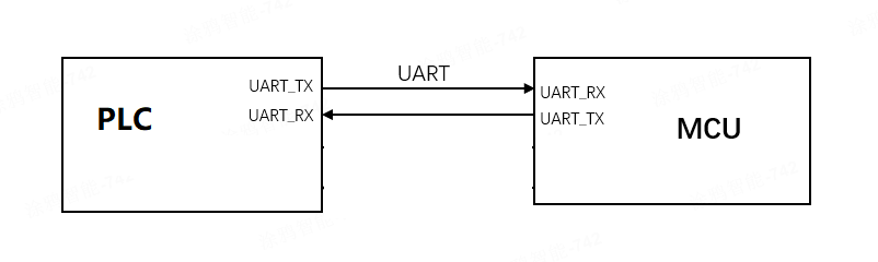
The following figure shows the connection between the PLC module and the MCU. Connect the UART TX and UART RX pins.
Serial communication
- Baud: 9600/115200 bps
- Data bit: 8
- Parity check: none
- Stop bit: 1
- Data flow control: none
- Supply voltage: Tuya’s PLC module and the MCU are supplied by 3.3V DC
The table below lists the UART pins for various PLC module models. Pin definitions might vary by firmware.
| Field | Bytes | Description |
|---|---|---|
| Header | 2 | 0x55AA |
| Version | 1 | 0x02 |
| Sequence number | 2 | xx xx |
| Command | 1 | 0x27 |
| Data length | 2 | N |
| Data | N | Data point (DP) message format |
| Checksum | 1 | xx |
Auto-baud detection
The PLC module supports two baud rates: 9600 bps and 115200 bps. The module supports automatic baud rate detection. Upon initial power up, it alternates between 9600 bps and 115200 bps to query product information. When the MCU responds at one of these rates, the module saves and configures that rate.
- The auto baud rate detection might vary by the key and version of the PLC module firmware.
- Auto baud rate detection occurs only during the initial communication between the module and the MCU in factory default mode. Once set, the baud rate cannot be changed.
Frame format
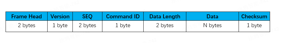
| Field | Description |
|---|---|
| Frame head | It is fixed to 0x55AA. |
| Version | The version of the serial protocol, used for protocol updates or extensions. The current version is 0x02. |
| Sequence number (SEQ) | The sequence number for data transmission, cycling from 0 to 0xfff0. This field is represented as xx xx below. |
| Command ID | The ID of a command. Commands are continuously added and updated. |
| Data length | The payload length. |
| Data | The payload data. |
| Checksum | Start from the header, add up all the bytes, and then divide the sum by 256 to get the remainder. This field is represented as xx below. |
- In a single frame, the maximum
Datasize for sending and receiving is 384 bytes. - All data greater than one byte is transmitted in big-endian format.
Command ID
| Command | Sender | Description |
|---|---|---|
| 0x01 | P | Query product information |
| 0x02 | P | Sync module’s network status |
| 0x03 | M | Reset or pair module |
| 0x00 | P | Sync app-initiated factory reset |
| 0x20 | M | Query module’s network status |
| 0x25 | M | Check gateway’s network status |
| 0x04 | P | Receive DP data |
| 0x2A | P | Receive DP data (group control) |
| 0x06 | M | Report DP data (trigger linkage) |
| 0x2C | M | Report DP data (not trigger linkage) |
| 0x28 | P | Query DP data |
| 0x27 | M | Send advertising packets |
| 0x43 | M | Send private commands via multicast |
| 0x41 | P | Configure scenes (for scene controllers) |
| 0x0A | M | Trigger scenes (for scene controllers) |
| 0x0B | P | Query MCU firmware version |
| 0x0C | P | Initiate OTA update |
| 0x0D | M | Request firmware updates |
| 0x0E | M | Report update result |
| 0x24 | M | Sync time |
- M: Refers to the MCU, which sends a command to the PLC module.
- P: Refers to the PLC module, which sends a command to the MCU.
Configuration commands
Query product information (0x01)
Each time the PLC module is powered on, it sends this command to the MCU, which must respond before sending any other commands to the module. Product information consists of the product ID and the MCU software version number. The PLC module also uses this command to check the MCU’s baud rate during their initial communication.
The module sends the following data.
| Field | Bytes | Description |
|---|---|---|
| Header | 2 | 0x55AA |
| Version | 1 | 0x02 |
| Sequence number | 2 | xx xx |
| Command | 1 | 0x01 |
| Data length | 2 | 0x0000 |
| Data | 0 | None |
| Checksum | 1 | xx |
Example: 55 AA 02 xx xx 01 00 00 xx.
The MCU responds with the following data.
| Field | Bytes | Description |
|---|---|---|
| Header | 2 | 0x55AA |
| Version | 1 | 0x02 |
| Sequence number | 2 | xx xx |
| Command | 1 | 0x01 |
| Data length | 2 | N |
| Data | N | Product information, for example, "p":"AIp08abcdefghijk". |
| Checksum | 1 | xx |
Product information is in JSON format, enclosed in curly braces ({}), with data presented as "key":"value". Below are the supported keys and values.
- (Required) p: The ID of the product created on the Tuya Developer Platform, such as
AIp08kLIAIp08kLIin the example above.
Example: 55 AA 02 xx xx 01 00 18 7b2270223a2241497030386b4c4941497030386b4c49227d xx.
In this example, the product information is: {"p":"AIp08kLIAIp08kLI"}.
Sync module’s network status (0x02)
The network status refers to the local PLC network, not the internet. After the module connects to a gateway, it is considered connected. The network status will remain unchanged despite the loss of gateway power or parent nodes. When the network status of the module changes, the module will proactively send its current status to the MCU.
The module sends the following data.
| Field | Bytes | Description |
|---|---|---|
| Header | 2 | 0x55AA |
| Version | 1 | 0x02 |
| Sequence number | 2 | xx xx |
| Command | 1 | 0x02 |
| Data length | 2 | 0x0001 |
| Data | 1 | The network status of the module |
| Checksum | 1 | xx |
The network status of the module:
0x00: Not connected, such as when the device is powered on for the first time, fails to pair, or is removed from the mobile app.0x01: Connected, indicating that the device has been added to a PLC network.0x02: Network error.0x03: The device is being paired.
Example: 55 AA 02 xx xx 02 00 01 01 xx, indicating the module is connected.
The MCU responds with the following data.
| Field | Bytes | Description |
|---|---|---|
| Header | 2 | 0x55AA |
| Version | 1 | 0x02 |
| Sequence number | 2 | xx xx |
| Command | 1 | 0x01 |
| Data length | 2 | 0x0000 |
| Data | 0 | None |
| Checksum | 1 | xx |
Example: 55 AA 02 xx xx 02 00 00 xx.
Unbind and clear data (0x00)
When Unbind and Clear Data is initiated on the mobile app, the module will notify the MCU of this command. The MCU then clears local data and restores factory settings accordingly.
The module sends the following data.
| Field | Bytes | Description |
|---|---|---|
| Header | 2 | 0x55AA |
| Version | 1 | 0x02 |
| Sequence number | 2 | xx xx |
| Command | 1 | 0x00 |
| Data length | 2 | 0x0001 |
| Data | 1 | 0x01 (default) |
| Checksum | 1 | xx |
The data field defaults to 0x01, which is reserved for future use.
Example: 55 AA 02 xx xx 00 00 01 01 xx.
The MCU responds with the following data.
| Field | Bytes | Description |
|---|---|---|
| Header | 2 | 0x55AA |
| Version | 1 | 0x02 |
| Sequence number | 2 | N |
| Command | 1 | 0x00 |
| Data length | 2 | 0x0001 |
| Data | 1 | 0x01 |
| Checksum | 1 | xx |
Example: 55 AA 02 xx xx 00 00 01 01 xx.
Reset or pair module (0x03)
The MCU instructs the module to enter pairing mode and perform a software reset.
The MCU sends the following data.
| Field | Bytes | Description |
|---|---|---|
| Header | 2 | 0x55AA |
| Version | 1 | 0x02 |
| Sequence number | 2 | xx xx |
| Command | 1 | 0x03 |
| Data length | 2 | 0x0001 |
| Data | 1 |
|
| Checksum | 1 | xx |
Example: 55 AA 02 xx xx 03 00 01 01 xx, indicating the module leaves the current network and joins a new one.
The module responds with the following data.
| Field | Bytes | Description |
|---|---|---|
| Header | 2 | 0x55AA |
| Version | 1 | 0x02 |
| Sequence number | 2 | xx xx |
| Command | 1 | 0x03 |
| Data length | 2 | 0x0000 |
| Data | 1 | None |
| Checksum | 1 | xx |
Example: 55 AA 02 xx xx 03 00 00 xx.
Query module’s network status (0x20)
When the module’s network status changes, it will notify the MCU via the command Sync module’s network status. The MCU can also request the module’s current network status.
The MCU sends the following data.
| Field | Bytes | Description |
|---|---|---|
| Header | 2 | 0x55AA |
| Version | 1 | 0x02 |
| Sequence number | 2 | xx xx |
| Command | 1 | 0x20 |
| Data length | 2 | 0x0000 |
| Data | 0 | None |
| Checksum | 1 | xx |
Example: 55 AA 02 xx xx 20 00 00 xx.
The module responds with the following data.
| Field | Bytes | Description |
|---|---|---|
| Header | 2 | 0x55AA |
| Version | 1 | 0x02 |
| Sequence number | 2 | xx xx |
| Command | 1 | 0x20 |
| Data length | 2 | 0x0001 |
| Data | 1 | The network status of the module |
| Checksum | 1 | xx |
See Sync module’s network status for the network status details.
Example: 55 AA 02 xx xx 20 00 01 01 xx, indicating the module is connected.
Check gateway’s network status (0x25)
The MCU checks the network status of the PLC gateway. If the gateway indicates it is online, the device is also considered online. The MCU can signify the network status accordingly.
The MCU sends the following data.
| Field | Bytes | Description |
|---|---|---|
| Header | 2 | 0x55AA |
| Version | 1 | 0x02 |
| Sequence number | 2 | xx xx |
| Command | 1 | 0x25 |
| Data length | 2 | 0x0000 |
| Data | 0 | None |
| Checksum | 1 | xx |
Example: 55 AA 02 xx xx 25 00 00 xx.
The module responds with the following data.
| Field | Bytes | Description |
|---|---|---|
| Header | 2 | 0x55AA |
| Version | 1 | 0x02 |
| Sequence number | 2 | xx xx |
| Command | 1 | 0x25 |
| Data length | 2 | 0x0001 |
| Data | 1 |
|
| Checksum | 1 | xx |
Example: 55 AA 02 xx xx 25 00 01 01 xx, indicating the gateway is online on the internet.
Application data transmission commands
Receive DP data (0x04)
When the module receives a DP message from a PLC gateway or sub-device, it notifies the MCU using this command. For example, when you send a DP message to a device using the Tuya app, the message is delivered to the gateway, which then sends it to the target device through the PLC network.
The module sends the following data.
| Field | Bytes | Description |
|---|---|---|
| Header | 2 | 0x55AA |
| Version | 1 | 0x02 |
| Sequence number | 2 | xx xx |
| Command | 1 | 0x04 |
| Data length | 2 | N |
| Data | N | Data point (DP) message format |
| Checksum | 1 | xx |
DP message format:
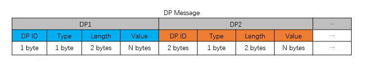
A DP message can include data from multiple DPs, with each DP’s data formatted as follows:
- DP ID: The ID of a DP defined on the Tuya Developer Platform.
- Type: The date type of DP. Some data types have a fixed length.
- Length: The length of the data in the
Valuefield. - Value: The payload.
Type:
| Type | Data type | Data length | Description |
|---|---|---|---|
| 0x00 | Raw | Custom | Raw data type in hex format, with customizable bytes. |
| 0x01 | Boolean | 1 | Boolean data type. Valid values include 0x00 and 0x01. |
| 0x02 | Value | 4 | Value data type, for example, 1, 23, and 104. |
| 0x03 | String | Custom | Custom string. |
| 0x04 | Enum | 1 | Enum data type, ranging from 0 to 255. |
| 0x05 | Bitmap | 1/2/4 | Bitmap data type, used to report error codes. |
Example: 55 AA 02 xx xx 04 00 05 03 01 00 01 01 xx, indicating the module received a DP message with data for one DP, as follows.
- DP ID:
03 - Type:
01 - Length:
00 01 - Value:
01
- A DP message can contain the data structures of multiple DPs, for example, when the mobile app sends several DPs to the device simultaneously.
- The raw type DP has only one data structure. Multiple raw type DPs cannot be sent simultaneously or combined with other types of DPs in one message.
The MCU returns the following data.
| Field | Bytes | Description |
|---|---|---|
| Header | 2 | 0x55AA |
| Version | 1 | 0x02 |
| Sequence number | 2 | xx xx |
| Command | 1 | 0x04 |
| Data length | 2 | 0x0000 |
| Data | 0 | None |
| Checksum | 1 | xx |
Example: 55 AA 02 xx xx 04 00 00 xx
Receive DP data for group control (0x2A)
When the module receives DP messages for group control, including multicast and broadcast, it notifies the MCU with this command. If a Tuya-enabled gateway is connected, the MCU is not required to respond to the received DP message because the gateway can automatically read the DP after sending a group control message.
The module sends the following data.
| Field | Bytes | Description |
|---|---|---|
| Header | 2 | 0x55AA |
| Version | 1 | 0x02 |
| Sequence number | 2 | xx xx |
| Command | 1 | 0x2A |
| Data length | 2 | N |
| Data | N | Data point (DP) message format |
| Checksum | 1 | xx |
Example: 55 AA 02 xx xx 2A 00 04 01 01 00 01 01 xx, indicating the module received a DP message for group control.
- DP ID:
01 - Type:
00 - Length:
01 - Value:
01
The MCU responds with the following data.
| Field | Bytes | Description |
|---|---|---|
| Header | 2 | 0x55AA |
| Version | 1 | 0x02 |
| Sequence number | 2 | xx xx |
| Command | 1 | 0x2A |
| Data length | 2 | 0x0000 |
| Data | 0 | None |
| Checksum | 1 | xx |
Example: 55 AA 02 xx xx 2A 00 00 xx.
Report DP data (trigger linkage) (0x06)
When the MCU detects a change in DP status, such as when the user presses a switch, it can report the updated DP to the module with this command to sync with the cloud. The module sends the received message to the gateway and waits for its response before replying to the MCU. Reporting DP data through this command can trigger a local or cloud linkage.
- If the gateway acknowledges the data reporting within the timeout, the module responds to the MCU with success.
- If the gateway fails to acknowledge the data reporting within the timeout, the module responds to the MCU with failure.
- If the module is not paired, it should immediately respond to the MCU with failure.
- The MCU can check if the connection between the module and the gateway works fine based on the module’s response.
Clearly specify the data that needs to trigger linkage and report it with the
0x06command. It is recommended that the MCU not report frequently but only report when linkage needs to be triggered.
The MCU sends the following data.
| Field | Bytes | Description |
|---|---|---|
| Header | 2 | 0x55AA |
| Version | 1 | 0x02 |
| Sequence number | 2 | xx xx |
| Command | 1 | 0x06 |
| Data length | 2 | N |
| Data | N | Data point (DP) message format |
| Checksum | 1 | xx |
Example: 55 AA 02 xx xx 06 00 05 03 01 00 01 01 xx.
This example shows the MCU proactively reporting a single DP, which can trigger a linkage.
- DP ID:
03 - DP type:
01 - DP length:
00 01 - DP value:
01
The module responds with the following data.
| Field | Bytes | Description |
|---|---|---|
| Header | 2 | 0x55AA |
| Version | 1 | 0x02 |
| Sequence number | 2 | xx xx |
| Command | 1 | 0x06 |
| Data length | 2 | 0x0001 |
| Data | 1 |
|
| Checksum | 1 | xx |
Example: 55 AA 02 xx xx 06 00 01 01 xx, indicating the DP message is reported successfully.
- Successful reporting: The module sends the DP message to the gateway and receives an acknowledgment in return.
- Failed reporting: The module is not paired, or the gateway acknowledgment times out.
- Data payload can contain only one raw type DP, which cannot be combined with other types of DPs for reporting.
Report DP data (not trigger linkage) (0x2C)
This is an extended command of 0x06, used to send device status to the cloud without directly triggering a linkage. For example, in a linkage where the light turns on when the switch is on and off when it is turned back. When the switch is turned off and then on, its status will sync with the cloud. If you want to prevent this sync from triggering a linkage action on the light, this command allows you to report data without initiating a linkage.
- After the device is paired or powered on, it is recommended to report DP data with this command to sync status. To prevent network congestion from simultaneous large-volume reporting, specify a random delay of 5 to 15 seconds.
- Check if the module and firmware you are using support this command.
Use0x2cto report ordinary data. The protocol stack will implement strategies based on the reported data to ensure network smoothness.
The MCU sends the following data.
| Field | Bytes | Description |
|---|---|---|
| Header | 2 | 0x55AA |
| Version | 1 | 0x02 |
| Sequence number | 2 | xx xx |
| Command | 1 | 0x2C |
| Data length | 2 | N |
| Data | N | Data point (DP) message format |
| Checksum | 1 | xx |
Example: 55 AA 02 xx xx 2C 00 05 03 01 00 01 01 xx.
This example shows the MCU proactively reporting a single DP to sync with the cloud, without triggering a linkage.
- DP ID:
03 - DP type:
01 - DP length:
00 01 - DP value:
01
The module responds with the following data.
| Field | Bytes | Description |
|---|---|---|
| Header | 2 | 0x55AA |
| Version | 1 | 0x02 |
| Sequence number | 2 | xx xx |
| Command | 1 | 0x2C |
| Data length | 2 | 0x0001 |
| Data | 1 |
|
| Checksum | 1 | xx |
Example: 55 AA 02 xx xx 2C 00 01 01 xx, indicating the DP message is reported successfully.
- Successful reporting: The module sends the DP message to the gateway and receives an acknowledgment in return.
- Failed reporting: The module is not paired, or the gateway acknowledgment times out.
- Data payload can contain only one raw type DP, which cannot be combined with other types of DPs for reporting.
Query DP data (0x28)
The gateway requests the device’s DP with this command. After receiving the request, the MCU acknowledges and then reports the specified DP. This command is typically used when the gateway powers on after a power loss or reconnects to a sub-device following a long disconnection.
The module sends the following data.
| Field | Bytes | Description |
|---|---|---|
| Header | 2 | 0x55AA |
| Version | 1 | 0x02 |
| Sequence number | 2 | xx xx |
| Command | 1 | 0x28 |
| Data length | 2 | N |
| Data | N | DP nums (1 byte) + DP list |
| Checksum | 1 | xx |
-
Example:
0x02 0x03 0x04indicates that the gateway requests 2 DPs of this device, with DP IDs0x03and0x04. -
Example:
55 AA 02 xx xx 28 00 03 02 03 04 xx, indicating the gateway requests DP3 and DP4 of the device.
The MCU responds with the following data.
| Field | Bytes | Description |
|---|---|---|
| Header | 2 | 0x55AA |
| Version | 1 | 0x02 |
| Sequence number | 2 | xx xx |
| Command | 1 | 0x28 |
| Data length | 2 | N |
| Data | 0 | DP nums (1 byte) + DP value list |
| Checksum | 1 | xx |
- DP nums:
02. - DP IDs are 03 and 04 of Boolean data type, and their values are both
1. - The DP value list is
03 01 00 01 01 04 01 00 01 01.
Example: 55 aa 02 xx xx 28 00 0b 02 03 01 00 01 01 04 01 00 01 01 xx
Send advertising packets (0x27)
Broadcast a DP message over the network so that all devices can receive it. For low power devices, a periodic wake-up must be specified, with the wake-up interval shorter than the advertising interval. Otherwise, the old packet will be overwritten.
Specify an advertising interval based on the network scale. If not specified, network congestion might occur.
The MCU sends the following data.
| Field | Bytes | Description |
|---|---|---|
| Header | 2 | 0x55AA |
| Version | 1 | 0x02 |
| Sequence number | 2 | xx xx |
| Command | 1 | 0x27 |
| Data length | 2 | N |
| Data | N | Data point (DP) message format |
| Checksum | 1 | xx |
Example: 55 AA 02 xx xx 27 08 05 02 00 04 00 00 00 1E xx, an advertising packet with the following content.
- DP ID:
05 - DP type:
02 - DP length:
00 04 - DP value:
00 00 00 1E
The module responds with the following data.
| Field | Bytes | Description |
|---|---|---|
| Header | 2 | 0x55AA |
| Version | 1 | 0x02 |
| Sequence number | 2 | xx xx |
| Command | 1 | 0x27 |
| Data length | 2 | 0x0001 |
| Data | 1 |
|
| Checksum | 1 | xx |
Example: 55 AA 02 xx xx 27 00 01 01 xx, indicating the advertising message is sent successfully.
Send DP message to group (0x43)
Send a DP message to a group via multicast to control Tuya-enabled devices. The DP message sent follows the controlled device’s DP format, which includes the DP ID, DP type, DP length, and DP value. The group ID is retrieved through another command (not defined yet). This command is only applicable to remote controls.
The MCU sends the following data.
| Field | Bytes | Description |
|---|---|---|
| Header | 2 | 0x55AA |
| Version | 1 | 0x02 |
| Sequence number | 2 | xx xx |
| Command | 1 | 0x43 |
| Data length | 2 | N |
| Data | N | Data point (DP) message format |
| Checksum | 1 | xx |
Example: 55 AA 02 xx xx 43 00 07 2A 08 01 01 00 01 01 xx, sending a DP message via multicast with the following content.
- Group ID:
0x2A08 - DP ID:
01 - DP type:
01 - DP length:
00 01 - DP value:
01
The module returns the following data.
| Field | Bytes | Description |
|---|---|---|
| Header | 2 | 0x55AA |
| Version | 1 | 0x02 |
| Sequence number | 2 | xx xx |
| Command | 1 | 0x43 |
| Data length | 2 | 0x0001 |
| Data | 1 |
|
| Checksum | 1 | xx |
Example: 55 AA 02 xx xx 43 00 01 01 xx, indicating the DP message is sent successfully via multicast.
Configure group information (for remote control only) (0x41)
The module sends the following data.
| Field | Bytes | Description |
|---|---|---|
| Header | 2 | 0x55AA |
| Version | 1 | 0x02 |
| Sequence number | 2 | xx xx |
| Command | 1 | 0x41 |
| Data length | 2 | N |
| Data | 4 | Key ID (1 byte) + group ID (2 bytes) + reserved (1 byte) |
| Checksum | 1 | xx |
Example: 55 AA 02 xx xx 41 00 04 01 00 02 03 xx, indicating that a group configuration command is received from the gateway.
- Key ID:
01 - Group ID:
0x0002 - Reserved:
0x03
The MCU responds with the following data.
| Field | Bytes | Description |
|---|---|---|
| Header | 2 | 0x55AA |
| Version | 1 | 0x02 |
| Sequence number | 2 | xx xx |
| Command | 1 | 0x41 |
| Data length | 2 | 0x0001 |
| Data | 1 |
|
| Checksum | 1 | xx |
Example: 55 AA 02 xx xx 41 00 01 01 xx.
Scene commands
A scene, also known as a linkage, refers to the execution of a specific action when a condition is met. Conditions can include time, weather, and device status, while actions refer to tasks or commands that a device is instructed to execute. For example, when the temperature sensor detects that the temperature exceeds 30°C, turn on the air conditioner and set it to 25°C.
A scene controller, such as a scene switch and remote control, serves as a condition in scenes. It typically has multiple buttons, each used to trigger a scene. For example, press button 1 to turn off all the lights and button 2 to turn them on.
Tuya-enabled PLC devices support both standard scenes and linkage scenes.
Standard scene
Creating a standard scene requires a gateway to send configurations. Once created, it can be triggered independently of the gateway. Even if the gateway loses power, the scene can function because the scene controller directly sends control commands to the target device.
Creating a standard scene requires the following:
- Access to scene creation: Open the app panel of the scene controller and select a button to create a scene.
- Actuator: A PLC device that performs the specified action and must be on the same gateway as the scene controller. You can add multiple actuators, but groups are not allowed.
The following figures show how to create and recall a standard scene.
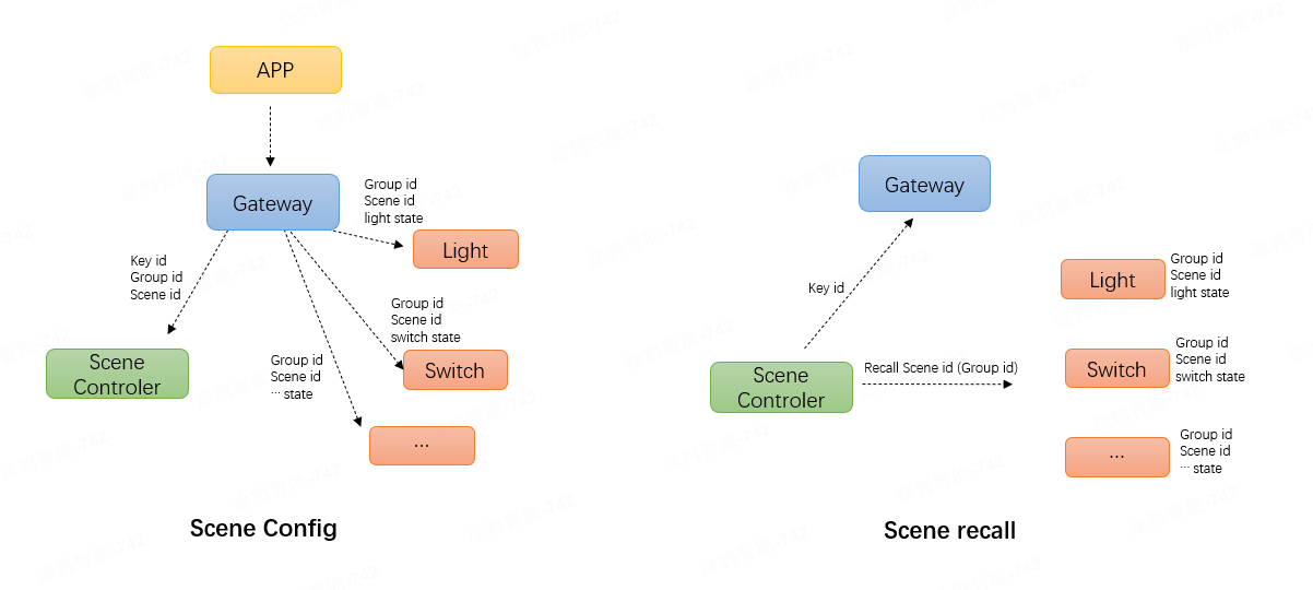
-
Configure a standard scene: After the mobile app creates a standard scene, it sends the key ID and scene ID to the scene controller via the gateway. The controller then sends the scene ID and action to the controlled device.
In a standard configuration workflow, DP17 is used to send commands. The module transparently transmits this DP to the MCU. After receiving and processing the command, the MCU must report a DP17 message upstream. The
dp payloadis the execution result. The DP length is 1 byte, and0x00indicates success. -
Recall a standard scene: Pressing a scene controller button broadcasts the scene ID through the default group
0x0000. After receiving the message, the controlled device filters the scene ID and matches it. If a match is found, it enters the state corresponding to the scene ID. Otherwise, no processing is performed.
Linkage scene
Linkage scene: Using a gateway or cloud as an intermediary, the trigger device reports its status to the gateway, which then verifies whether the linkage has been managed locally. A scene managed locally is called gateway linkage, while a scene managed in the cloud is referred to as cloud linkage.
- Gateway linkage: The PLC gateway stores linkage data. When a trigger device reports its status, the gateway controls the actuator based on this stored data. For example, gateway linkage applies when both the temperature sensor and air conditioner are connected to the same gateway.
- Cloud linkage: The cloud stores linkage data. When a trigger device reports its status to the gateway, the gateway forwards this information to the cloud, which then controls the actuator based on the stored data. For example, when a PLC device serves as a trigger and a Wi-Fi device acts as an actuator, cloud linkage is typically used.
You do not need to check whether a linkage scene is gateway or cloud-based. The Tuya Developer Platform determines the type based on the device type selected by the user during scene creation.
Scene commands apply only to scene controllers and require specific module firmware. The type of scene depends on how users create it.
Trigger scenes (for scene controllers) (0x0A)
This command is used to trigger a standard scene. A cloud scene is created using the Tuya-enabled mobile app instead of the scene controller’s app panel. The controller acts as a trigger for the linkage. When a button is pressed, the controller sends a standard scene recall command via the default group 0x0000 to broadcast the scene ID. If a standard scene is not configured, this command will not receive a response.
To trigger a cloud-based scene, the MCU needs to report to the gateway the DPID corresponding to the channel to be executed. This DPID is the one assigned to each channel by the platform when the product is created, not the scene ID sent by 0x41.
The MCU sends the following data.
| Field | Bytes | Description |
|---|---|---|
| Header | 2 | 0x55AA |
| Version | 1 | 0x02 |
| Sequence number | 2 | xx xx |
| Command | 1 | 0x0A |
| Data length | 2 | 0x0001 |
| Data | 1 | The ID of the scene. |
| Checksum | 1 | xx |
Example: 55 AA 02 xx xx 0A 00 01 sceneid xx , triggering a scene with key ID 1.
The module responds with the following data.
| Field | Bytes | Description |
|---|---|---|
| Header | 2 | 0x55AA |
| Version | 1 | 0x02 |
| Sequence number | 2 | xx xx |
| Command | 1 | 0x41 |
| Data length | 2 | 0x0001 |
| Data | 1 |
|
| Checksum | 1 | xx |
Example: 55 AA 02 xx xx 0A 00 01 01 xx, indicating the scene is triggered successfully. The operation is considered successful if the command is sent to any module successfully.
Production testing commands
RF production testing (0x08)
The MCU can proactively send this command to the module to initiate RF testing, verifying the module’s capability to send and receive RF data correctly.
A dongle must be prepared before starting the RF test.
Upon receiving the command, the module enters RF test mode and begins transmitting raw data packets of a specific format over the air. The dongle, upon receiving these packets, returns corresponding acknowledgment packets. The module extracts the RF test result value from the received acknowledgments.
After the RF test concludes, the module sends the RF test results to the MCU, enabling the MCU to evaluate the module’s transmission and reception performance.
RF production testing must be performed in an unpaired state. Upon test completion, the module must be restarted to resume normal operation.
The MCU sends the following data.
| Field | Bytes | Description |
|---|---|---|
| Header | 2 | 0x55AA |
| Version | 1 | 0x02 |
| Sequence number | 2 | xx xx |
| Command | 1 | 0x08 |
| Data length | 2 | 0x0001 |
| Data | 1 | Reserved, 1 byte |
| Checksum | 1 | xx |
Example: 55 AA 02 xx xx 08 00 01 00 xx, conducting an RF test.
The module responds with the following data.
| Field | Bytes | Description |
|---|---|---|
| Header | 2 | 0x55AA |
| Version | 1 | 0x02 |
| Sequence number | 2 | xx xx |
| Command | 1 | 0x08 |
| Data length | 2 | 0x0007 |
| Data | 7 | RF test results |
| Checksum | 1 | xx |
RF test results (status: 1 byte, RF data: 6 bytes):
-
Data[0] =
0x00, indicating the test failed. Data[1] =0x00(Fixed value), indicating no acknowledgment packet was received. -
Data[0] =
0x01, indicating the test passed. Data[1] = RSSI, Data[2] = SNR, Data[3-6] = frequency (big-endian format).
Example: 55 AA 02 00 00 08 00 07 01 C7 3D 00 00 01 46 5C indicates that the RF test was successful, RSSI: -57, SNR: 61, and frequency: 326.
MCU OTA update commands
This section describes the process to perform an MCU OTA update through the module.
- The gateway requests the MCU firmware version and reports it to the cloud.
- When the cloud detects that the PID (or device ID) has MCU OTA updates configured and a new update is available, it will notify the module to perform the MCU OTA.
- After receiving the notification from the cloud, the module will notify the MCU.
- The MCU requests and installs the update file.
- After the update is complete, report the OTA results and the new MCU firmware version using the response format specified in the MCU Firmware Version Query.
Query MCU firmware version (0x0B)
Sync the current MCU firmware version with the cloud for display or OTA update check. This command must be implemented if you need MCU OTA updates. This command works to:
- Gateway queries MCU version number: The module notifies the MCU of the gateway’s version query and waits for a response.
- Device proactively reports MCU version number: For example, after a successful pairing or OTA update, the MCU reports its current version number to the module, which then sends it to the gateway.
The module sends the following data.
| Field | Bytes | Description |
|---|---|---|
| Header | 2 | 0x55AA |
| Version | 1 | 0x02 |
| Sequence number | 2 | xx xx |
| Command | 1 | 0x0B |
| Data length | 2 | 0x0000 |
| Data | 0 | None |
| Checksum | 1 | xx |
Example: 55 AA 02 xx xx 0B 00 00 xx, querying the current version number of the MCU.
The MCU responds with the following data.
| Field | Bytes | Description |
|---|---|---|
| Header | 2 | 0x55AA |
| Version | 1 | 0x02 |
| Sequence number | 2 | xx xx |
| Command | 1 | 0x0B |
| Data length | 2 | 3 |
| Data | 3 | MCU update channel (1 byte) + firmware version number (2 bytes) |
| Checksum | 1 | xx |
MCU update channel: When users upload firmware on the Tuya Developer Platform, they need to select the MCU’s OTA update channel and fill in the value assigned by the platform. The MCU firmware version number is represented as two bytes in binary format xxxx.yyyy.zzzzzzzz. For example, 0x1222 (binary 0001 0002 00100010) represents the version number 1.2.34. Due to the byte limitation, the maximum version number is 15.15.255.
Example 1: 55 AA 02 xx xx 0B 00 03 09 12 22 xx, indicating the current version number is 0x1222, which in binary is 0001 0002 00100010, corresponding to version 1.2.34.
Example 2: 55 AA 02 xx xx 0B 00 06 09 12 22 0a 12 23 xx
Indicating the update channel is 9, and the current version number is 0x1222, which in binary is 0001 0002 00100010, corresponding to version 1.2.34.
- The cloud uses this command to retrieve the MCU version number and decide whether to push an OTA update.
- The MCU can proactively send its version number to the module without needing a query, and the module then reports it to the gateway.
Initiate OTA update (0x0C)
If a product has the MCU OTA update feature configured and the push service enabled on the Tuya Developer Platform, the mobile app will notify users or automatically initiate an update when an update is available. The module receives the command from the gateway and notifies the MCU to prepare for an OTA update.
The module sends the following data.
| Field | Bytes | Description |
|---|---|---|
| Header | 2 | 0x55AA |
| Version | 1 | 0x02 |
| Sequence number | 2 | xx xx |
| Command | 1 | 0x0C |
| Data length | 2 | 0x000b |
| Data | 11 | Update channel (1 byte) + new firmware version number (2 bytes) + firmware size in bytes (4 bytes) + firmware checksum (4 bytes) |
| Checksum | 1 | xx |
- Update channel (1 byte): When users upload firmware on the Tuya Developer Platform, they need to select the MCU’s OTA update channel. Fill in the value assigned by the platform.
- New firmware version number (2 bytes): For example,
0x1222indicates version 1.2.34. - Firmware size (4 bytes): Measured in bytes.
- Firmware checksum (4 bytes): The checksum of the entire firmware from the first byte. After the MCU receives the complete firmware update, it should calculate the checksum and compare it to this field. If the checksum does not match, an issue might have occurred during transmission, causing the update to fail.
Example: 0x55 AA 02 xx xx 0C 00 0a 09 12 22 00 00 78 00 30 31 32 33 xx, indicating an OTA update notification with the following content:
- Update channel: 9.
- New firmware version number:
0x1222, which is version 1.2.34. - Firmware size:
0x00007800, which is 30 KB. - Firmware checksum:
0x30313233.
The MCU responds with the following data.
| Field | Bytes | Description |
|---|---|---|
| Header | 2 | 0x55AA |
| Version | 1 | 0x02 |
| Sequence number | 2 | xx xx |
| Command | 1 | 0x0C |
| Data length | 2 | 0x0001 |
| Data | 1 | 0x00 (default) |
| Checksum | 1 | xx |
Example: 55 AA 02 xx xx 0C 00 01 00 xx.
The module currently does not process the MCU response to the command 0x0C. If the MCU detects a data error, it can request the packet to be resent.
Request firmware updates (0x0D)
After receiving the OTA update notification from the gateway, the device can start downloading the OTA file. The device manages the download process by sending a file request that includes the data offset and packet size. After receiving the request from the device, the gateway returns the packet offset and update data. This command is initiated by the MCU and sent to the gateway by the module.
The MCU sends the following data.
| Field | Bytes | Description |
|---|---|---|
| Header | 2 | 0x55AA |
| Version | 1 | 0x02 |
| Sequence number | 2 | xx xx |
| Command | 1 | 0x0D |
| Data length | 2 | 0x0009 |
| Data | 9 | Update channel (1 byte) + new firmware version number (2 bytes) + packet offset (4 bytes) + packet size (2 bytes) |
| Checksum | 1 | xx |
- Update channel (1 byte): When users upload firmware on the Tuya Developer Platform, they need to select the MCU’s OTA update channel. Fill in the value assigned by the platform.
- New firmware version number (2 bytes): For example,
0x1222indicates version 1.2.34. - Packet offset (4 bytes): The offset of the requested data in the OTA file, in bytes.
- Packet size (2 byte): The size of the requested packet, in bytes, up to 384 bytes.
Example: 0x55 AA 02 xx xx 0C 00 09 09 12 34 00 00 10 00 00 30 xx, requesting a 48-byte packet starting from the address 4096.
- Update channel (1 byte): 9.
- New firmware version number:
0x1222, which is version 1.2.34. - Packet offset:
0x00001000, indicating an offset address of 4096. - Packet size:
0x0030, requesting 48 bytes of data.
The module responds with the following data.
| Field | Bytes | Description |
|---|---|---|
| Header | 2 | 0x55AA |
| Version | 1 | 0x02 |
| Sequence number | 2 | xx xx |
| Command | 1 | 0x0D |
| Data length | 2 | N |
| Data | N | Result (1 byte) + update channel (1 byte) + new firmware version number (2 bytes) + packet offset (4 bytes) + payload |
| Checksum | 1 | xx |
- Result:
0x00for success and0x01for failure. When the request fails, there is no following data. - Update channel (1 byte): When users upload firmware on the Tuya Developer Platform, they need to select the MCU’s OTA update channel. Fill in the value assigned by the platform.
- New firmware version number (2 bytes):
0x1222indicates version 1.2.34. - Packet offset (4 bytes): The offset of the requested data in the OTA file, in bytes.
- Payload (N bytes): The actual data.
Example: 55 AA 02 xx xx 0D xxxx 00 09 12 22 00 00 10 00 ... xx, indicating a successful request (payload represented by ellipsis).
Report update result (0x0E)
After completing an MCU OTA update, the MCU initiates this command to report the update result to the gateway.
The MCU sends the following data.
| Field | Bytes | Description |
|---|---|---|
| Header | 2 | 0x55AA |
| Version | 1 | 0x02 |
| Sequence number | 2 | xx xx |
| Command | 1 | 0x0E |
| Data length | 2 | 0x0004 |
| Data | 4 | Result (1 byte) + update channel (1 byte) + new firmware version number (2 bytes) |
| Checksum | 1 | xx |
- Result (1 byte):
0x00for a successful update and0x01for a failed update.
Example: 0x55 AA 02 xx xx 0E 00 04 00 09 12 22 xx, indicating the MCU OTA update succeeded.
- Result:
0x00, indicating a successful MCU OTA update. - Update channel: 9.
- New firmware version number:
0x1222, which is version 1.2.34.
The module responds with the following data.
| Field | Bytes | Description |
|---|---|---|
| Header | 2 | 0x55AA |
| Version | 1 | 0x02 |
| Sequence number | 2 | xx xx |
| Command | 1 | 0x0E |
| Data length | 2 | 0x0001 |
| Data | 1 |
|
| Checksum | 1 | xx |
Example: 0x55 AA 02 xx xx 0E 00 01 00 xx.
Time service
Sync time (0x24)
Some devices require the current time to implement features such as local schedules or information displays. The device can request time information from the gateway, which responds with the data after time zone conversion. After receiving the time sync command from the MCU, the module sends a time request to the gateway and relays the response back to the MCU.
The MCU sends the following data.
| Field | Bytes | Description |
|---|---|---|
| Header | 2 | 0x55AA |
| Version | 1 | 0x02 |
| Sequence number | 2 | xx xx |
| Command | 1 | 0x24 |
| Data length | 2 | 0x0000 |
| Data | 0 | None |
| Checksum | 1 | xx |
Example: 55 AA 02 xx xx 24 00 00 xx, indicating the MCU initiates a time sync request.
The module responds with the following data.
| Field | Bytes | Description |
|---|---|---|
| Header | 2 | 0x55AA |
| Version | 1 | 0x02 |
| Sequence number | 2 | xx xx |
| Command | 1 | 0x24 |
| Data length | 2 | 0x0008 |
| Data | 8 | Unix timestamp (4 bytes) + local timestamp (4 bytes) |
| Checksum | 1 | xx |
- Unix timestamp: The number of seconds that have elapsed since January 1, 1970, at 00:00:00 Greenwich Mean Time (GMT).
- Local timestamp: Calculated by adding the time zone offset and daylight saving time (DST) (if applicable) to the Unix timestamp. Local time typically prevails.
Example: 55 AA 02 xx xx 24 00 08 66 45 DB F0 66 46 4C 70 xx.
- Unix time:
0x6645DBF0. - Local time:
0x66464C70.
Version history
| Changes | Date | Description |
|---|---|---|
| Publish | February 27, 2025 | The first release of PLC serial communication. |
| Adjusted scene-related commands | October 31, 2025 |
|
Is this page helpful?
YesFeedbackIs this page helpful?
YesFeedback


