Wi-Fi Power-Off
Overview
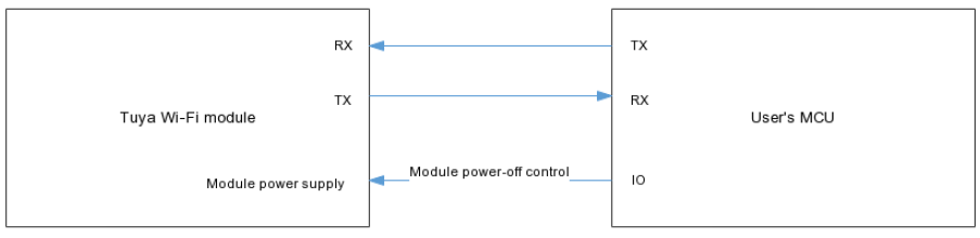
This topic describes the serial protocol that is used to implement serial communication between Tuya’s Wi-Fi module and the third-party MCU.
-
This protocol applies to devices that use Wi-Fi modules and cannot use an external power supply. During the development of MCU programs, power-off management is especially important. You can try to reduce the power-on time of the Wi-Fi module to reduce the power consumption of the device.
A general flow for data upload is offered. You can implement the required features from the protocol. During development, you can adjust relevant control logic as needed.
-
Many devices can function even without Wi-Fi enabled. Users may not use the Wi-Fi feature for some reason.
To reduce unnecessary power consumption when the Wi-Fi module is power on in this case, you can design a physical button or an option on the device. When users press this button or enable this option, the MCU powers on the Wi-Fi module for data transmission only when data changes.
Serial communication
- Baud: 9600
- Data bit: 8
- Parity check: none
- Stop bit: 1
- Data flow control: none
MCU: microcontroller unit. Your MCU communicates with Tuya’s modules through the serial port. The serial protocol is designed to enable full-duplex communication between the device and the server.
Frame format
| Field | Length (byte) | Description |
|---|---|---|
| Header | 2 | It is fixed to 0x55aa. |
| Version | 1 | It is used for updates and extensions. |
| Command | 1 | The frame type. |
| Data length | 2 | Big-endian format. |
| Data | N | - |
| Checksum | 1 | Start from the header, add up all the bytes, and then divide the sum by 256 to get the remainder. |
Description:
-
All data greater than one byte is transmitted in big-endian format.
-
All sample data in the protocol is in hexadecimal format.
-
The Wi-Fi module sends packets and waits for a response. If no response is received within one second, the unanswered packets will be retransmitted three times.
-
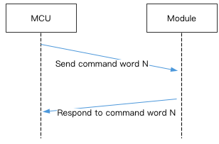
Typically, one command is sent by one party and received by the other party synchronously. That is, one party sends a command and waits for a response from the other party. If the sender does not receive a correct response packet within a specified time period, the transmission times out.
For more information, see Protocol list.
-
The MCU reports status synchronously. Assume that the MCU reports a command
Y. The data transmission is as follows.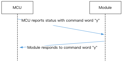
Data units
-
The DP command and status data units are defined as follows:
Field Length (byte) Description dpid 1 The DP ID. type 1 The data type of DP defined on the Tuya Developer Platform. For more information, see the description of the typefield in the following table.len 2 The length of a value, in bytes. For more information, see the description of the typefield in the following table.value 1/2/4/N Represented in hexadecimal format. Data greater than one byte is transmitted in big-endian format. Description of the
typefield:typeType Data length (byte) Description 0x00 Raw N Represents a DP of raw data type. The module transmits the raw data to the receiver. 0x01 Boolean 1 Represents a DP of Boolean data type. Valid values include 0x00and0x01.0x02 Value 4 Represents a DP of integer data type, in big-endian format. 0x03 String N Represents a DP of string data type. 0x04 Enum 1 Represents a DP of enum data type, ranging from 0 to 255. 0x05 Bitmap 1/2/4 Data greater than one byte is transmitted in big-endian format. -
Except for the raw data type, all others belong to the object type.
-
The MCU can report the status of multiple DPs.
Protocol list
Query product information
-
Product ID (PID): A unique identifier assigned to each product created on the Developer Platform for storing product information in the cloud.
-
Product information consists of the product ID and the MCU software version number.
-
MCU software version number: It is expressed in dot-decimal notation
x.x.xwherexis a decimal digit between 0 and 99.
The module sends the following data.
| Field | Length (byte) | Description |
|---|---|---|
| Header | 2 | 0x55aa |
| Version | 1 | 0x00 |
| Command | 1 | 0x01 |
| Data length | 2 | 0x0000 |
| Data | 0 | None |
| Checksum | 1 | Start from the header, add up all the bytes, and then divide the sum by 256 to get the remainder. |
The module sends the following data.
55 aa 00 01 00 00 00
The MCU returns the following data.
| Field | Length (byte) | Description |
|---|---|---|
| Header | 2 | 0x55aa |
| Version | 1 | 0x00 |
| Command | 1 | 0x01 |
| Data length | 2 | N |
| Data | N | {"p":"vHXEcqntLpkAl***", "v":"1.0.0"} |
| Checksum | 1 | Start from the header, add up all the bytes, and then divide the sum by 256 to get the remainder. |
Example: {"p":"vHXEcqntLpkAl***","v":"1.0.0"}
-
p: Indicates the product ID isvHXEcqntLpkAl***, which is the PID of a product created on the Developer Platform. -
v: Indicates the MCU version is 1.0.0.
The MCU returns the following data.
55 aa 00 01 00 24 7b 22 70 22 3a 22 76 48 58 45 63 71 6e 74 4c 70 6b 41 6c 4f 73 79 22 2c 22 76 22 3a 22 31 2e 30 2e 30 22 7d bf
Report network status
| Network status | Description | Status value |
|---|---|---|
| Status 1 | Wi-Fi EZ mode setup | 0x00 |
| Status 2 | Wi-Fi AP mode setup | 0x01 |
| Status 3 | The Wi-Fi network is set up, but the device is not connected to the router. | 0x02 |
| Status 4 | The Wi-Fi network is set up, and the device is connected to the router. | 0x03 |
| Status 5 | The device is connected to the router and the cloud. | 0x04 |
Description:
-
When the Wi-Fi status changes, the module will proactively send the current status to the MCU.
-
The MCU gets the current network status and indicates the pairing mode accordingly.
-
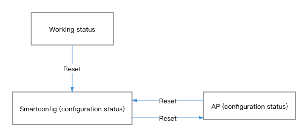
It is recommended to implement both AP and EZ pairing modes to ensure successful device pairing, especially if EZ mode fails due to compatibility issues with routers.
The module sends the following data.
| Field | Length (byte) | Description |
|---|---|---|
| Header | 2 | 0x55aa |
| Version | 1 | 0x00 |
| Command | 1 | 0x02 |
| Data length | 2 | 0x0001 |
| Data | 1 | Valid values that represent the Wi-Fi network status:
|
| Checksum | 1 | Start from the header, add up all the bytes, and then divide the sum by 256 to get the remainder. |
The module sends the following data.
55 aa 00 02 00 01 04 06, indicating the device is connected to the router and the cloud.
The MCU returns the following data.
| Field | Length (byte) | Description |
|---|---|---|
| Header | 2 | 0x55aa |
| Version | 1 | 0x00 |
| Command | 1 | 0x02 |
| Data length | 2 | 0x0000 |
| Data | 0 | None |
| Checksum | 1 | Start from the header, add up all the bytes, and then divide the sum by 256 to get the remainder. |
The MCU returns the following data.
55 aa 00 02 00 00 01
Reset Wi-Fi
The figure below illustrates the alternating pairing mode after a reset.
The MCU sends the following data.
| Field | Length (byte) | Description |
|---|---|---|
| Header | 2 | 0x55aa |
| Version | 1 | 0x00 |
| Command | 1 | 0x03 |
| Data length | 2 | 0x0000 |
| Data | 0 | None |
| Checksum | 1 | Start from the header, add up all the bytes, and then divide the sum by 256 to get the remainder. |
The MCU sends the following data.
55 aa 00 03 00 00 02
The module returns the following data.
| Field | Length (byte) | Description |
|---|---|---|
| Header | 2 | 0x55aa |
| Version | 1 | 0x00 |
| Command | 1 | 0x03 |
| Data length | 2 | 0x0000 |
| Data | 0 | None |
| Checksum | 1 | Start from the header, add up all the bytes, and then divide the sum by 256 to get the remainder. |
The module returns the following data.
55 aa 00 03 00 00 02
Reset Wi-Fi and select pairing mode
-
Compared to Reset Wi-Fi, this command enables the MCU to select the pairing mode after a reset.
-
You can implement this protocol as needed.
The MCU sends the following data.
| Field | Length (byte) | Description |
|---|---|---|
| Header | 2 | 0x55aa |
| Version | 1 | 0x00 |
| Command | 1 | 0x04 |
| Data length | 2 | 0x0001 |
| Data | 1 |
|
| Checksum | 1 | Start from the header, add up all the bytes, and then divide the sum by 256 to get the remainder. |
The MCU instructs the module to enter AP mode:
55 aa 00 04 00 01 01 05
The module returns the following data.
| Field | Length (byte) | Description |
|---|---|---|
| Header | 2 | 0x55aa |
| Version | 1 | 0x00 |
| Command | 1 | 0x04 |
| Data length | 2 | 0x0000 |
| Data | 0 | None |
| Checksum | 1 | Start from the header, add up all the bytes, and then divide the sum by 256 to get the remainder. |
The module returns the following data.
55 aa 00 04 00 00 03
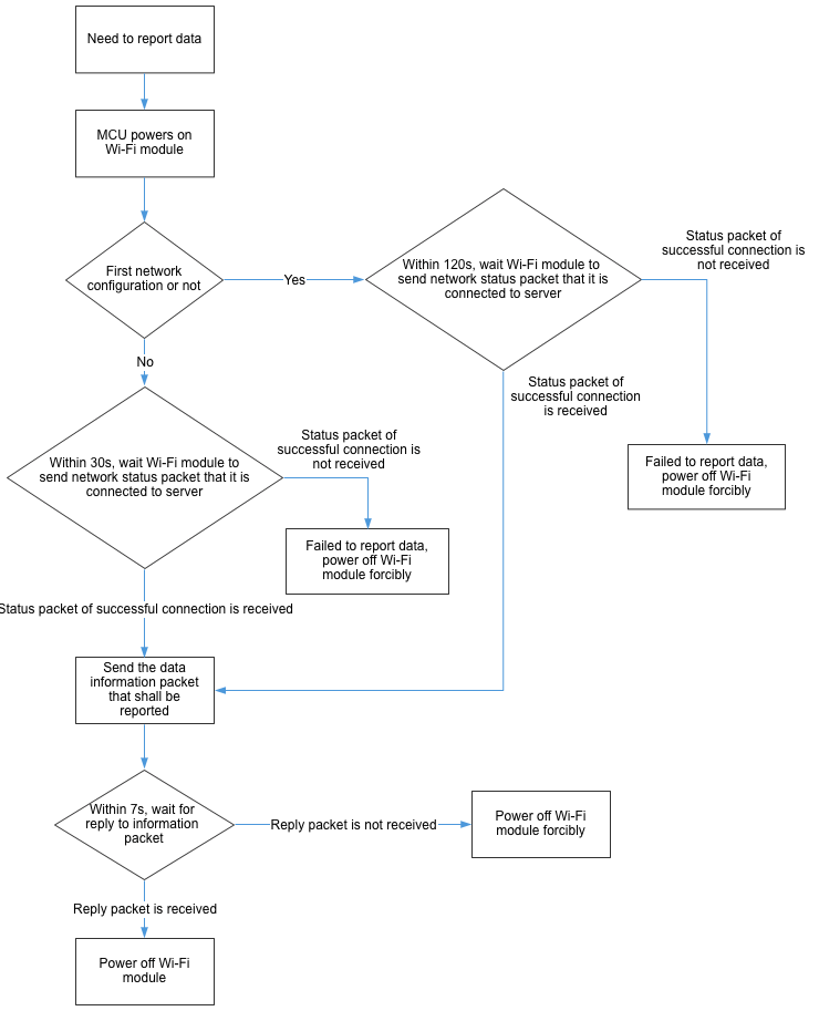
Report real-time status
This command allows devices that require real-time pushes, such as alarms, to make quick status reporting.
The MCU can report real-time status data through this protocol.
-
Status data is directly sent to the cloud, which requires the device to be connected to the cloud. Otherwise, data reporting will fail.
-
This is a synchronous command. The MCU sends data and waits seven seconds for a response from the module.
-
The module sends a network status packet to the MCU, indicating its connection to the server. The MCU then sends data reporting packets to the module. Note that storage is not available for such data uploads. If the MCU does not receive the network status packet, it will force the device to power off. The waiting time depends on the network condition and first-time pairing.
- When a device is paired for the first time, factors like activation, initialization, or poor network connectivity may delay the completion of Wi-Fi setup and cloud connectivity. You can set the timeout to 120 seconds.
- For a paired device, you can set a 30-second timeout to account for potential network issues.
-
You can send single or multiple DPs in a packet as needed.
The MCU sends the following data.
| Field | Length (byte) | Description |
|---|---|---|
| Header | 2 | 0x55aa |
| Version | 1 | 0x00 |
| Command | 1 | 0x05 |
| Data length | 2 | It depends on the types and the number of data units. |
| Data | N | Single or multiple data units. |
| Checksum | 1 | Start from the header, add up all the bytes, and then divide the sum by 256 to get the remainder. |
The module returns the following data.
| Field | Length (byte) | Description |
|---|---|---|
| Header | 2 | 0x55aa |
| Version | 1 | 0x00 |
| Command | 1 | 0x05 |
| Data length | 2 | 0x0001 |
| Data | 1 |
|
| Checksum | 1 | Start from the header, add up all the bytes, and then divide the sum by 256 to get the remainder. |
Report a single DP:
The DP 109 is of Boolean data type, and its value is 1.
55 aa 00 05 00 05 6d 01 00 01 01 79
Report multiple DPs:
The DP 109 is of Boolean data type, and its value is 1.
The DP 102 is of string data type, and its value is 201804121507 that is transferred in ASCII mode. The MCU sends the following data.
55 aa 00 05 00 15 6d 01 00 01 01 66 03 00 0c 32 30 31 38 30 34 31 32 31 35 30 37 5d
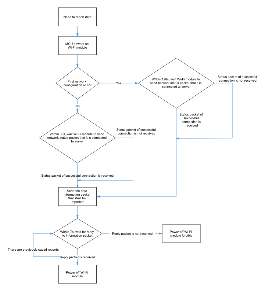
Report record-type data (with cache)
For the door lock, the status data of multiple DPs is processed as one piece of record in the server. In case of transient network failure, this command can store data that failed to be reported.
This command allows the MCU to send a piece of record-type data that includes multiple DPs to the Wi-Fi module for reporting it to the cloud. If the device is disconnected from the network when the data is being reported, the module will store this data and send it on the next reporting operation.
-
Each time when a stranded record is reported successfully, the module returns
0x01through the command0x09. The MCU determines whether to power off the module based on the return value. After sending a record, the MCU waits seven seconds for a response from the module. If no response is received, the MCU considers that anomalies occur and forces the module to power off. -
If the network works fine, the module connects to the server within about four seconds after being powered on. After power on, the MCU waits for the module’s network status. The waiting time depends on the network condition and first-time pairing.
- When a device is paired for the first time, factors like activation, initialization, or poor network connectivity may delay the completion of Wi-Fi setup and cloud connectivity. You can set the timeout to 120 seconds.
- For a paired device, you can set a 30-second timeout to account for potential network issues.
- If the MCU does not receive the network status packet, it still reports data to the module and waits for the result.
-
The maximum payload size for each packet is 80 bytes. The actual size varies based on the DP data. If no network is available and the length exceeds the limit, the Wi-Fi module will return a failure.
-
The module can store a maximum of 20 historical records. When the limit is reached, the newest record will overwrite the oldest one.
-
When the module successfully reports a record, or writes stranded data to the flash memory due to network failure, it returns
0x00indicating successful reporting. When the network works fine, each time the module successfully reports one of the stranded records, it returns0x01. In other cases, it returns0x02to indicate failed reporting. -
Time data: If the server requires data upload time, the local time in the packet prevails. When reporting data, the MCU should include the local time in the specified format and set the time flag Data[0] in the local time protocol to
1. When the Wi-Fi module detects that the time flag is set to1, it will use the MCU’s local time. Ensure the accuracy of the time data.
How it works:
The MCU sends the following data.
| Field | Length (byte) | Description |
|---|---|---|
| Header | 2 | 0x55aa |
| Version | 1 | 0x00 |
| Command | 1 | 0x08 |
| Data length | 2 | It depends on the types and the number of data units. |
| Data | 7 | Data[0]: indicates whether the local time is included.
|
| N | Single or multiple data units. | |
| Checksum | 1 | Start from the header, add up all the bytes, and then divide the sum by 256 to get the remainder. |
The module returns the following data.
| Field | Length (byte) | Description |
|---|---|---|
| Header | 2 | 0x55aa |
| Version | 1 | 0x00 |
| Command | 1 | 0x08 |
| Data length | 2 | 0x0001 |
| Data | 1 |
|
| Checksum | 1 | Start from the header, add up all the bytes, and then divide the sum by 256 to get the remainder. |
Report the status of a single DP: The DP 109 is of Boolean data type, and its value is 1. The MCU sends the following data.
-
55 aa 00 08 00 0c 01 12 04 13 0d 03 1d 6d 01 00 01 01 da// The local time prevails. -
55 aa 00 08 00 0c 00 12 04 13 0d 04 14 6d 01 00 01 01 d1// The server time prevails.
Report multiple DPs:
-
The DP 109 is of Boolean data type, and its value is
1. -
The DP 102 is of string data type, and its value is
201804121507that is transferred in ASCII mode. The MCU sends the following data. -
55 aa 00 08 00 1c 00 12 04 13 0d 06 04 6d 01 00 01 01 66 03 00 0c 32 30 31 38 30 34 31 32 31 35 30 37 a7// The server time prevails. -
55 aa 00 08 00 1c 01 12 04 13 0d 08 2e 6d 01 00 01 01 66 03 00 0c 32 30 31 38 30 3431 32 31 35 30 37 d4// The local time prevails.
Send commands
The module sends control commands to the MCU asynchronously. The MCU acknowledges receipt of the command and executes a specific operation.
The module sends the following data.
| Field | Length (byte) | Description |
|---|---|---|
| Header | 2 | 0x55aa |
| Version | 1 | 0x00 |
| Command | 1 | 0x09 |
| Data length | 2 | It depends on the types and the number of data units. |
| Data | N | Data units |
| Checksum | 1 | Start from the header, add up all the bytes, and then divide the sum by 256 to get the remainder. |
Suppose that DP 3 of Boolean type is used for on/off control, and 1 means to turn on the device. The module sends the following to the MCU.
55 aa 00 09 00 05 03 01 00 01 01 13
The MCU returns the following data.
| Field | Length (byte) | Description |
|---|---|---|
| Header | 2 | 0x55aa |
| Version | 1 | 0x00 |
| Command | 1 | 0x09 |
| Data length | 2 | 0x0000 |
| Data | 0 | None |
| Checksum | 1 | Start from the header, add up all the bytes, and then divide the sum by 256 to get the remainder. |
The MCU sends ACK message:
55 aa 00 09 00 00 08
Get the local time
-
After the MCU receives the status of a successful cloud connection, it sends this command to request the local time.
-
The request might fail due to poor network conditions. For time-critical devices such as door locks, you can set a three-second request interval to handle the situation that the MCU fails to get the time data for its first time-sync.
The MCU sends the following data.
| Field | Length (byte) | Description |
|---|---|---|
| Header | 2 | 0x55aa |
| Version | 1 | 0x00 |
| Command | 1 | 0x06 |
| Data length | 2 | 0x0000 |
| Data | 0 | None |
| Checksum | 1 | Start from the header, add up all the bytes, and then divide the sum by 256 to get the remainder. |
The MCU gets the local time:
55 aa 00 06 00 00 05
The module returns the following data.
| Field | Length (byte) | Description |
|---|---|---|
| Header | 2 | 0x55aa |
| Version | 1 | 0x00 |
| Command | 1 | 0x06 |
| Data length | 2 | 0x0008 |
| Data | Data | The data length is 8 bytes. Data[0]: indicates whether the local time is obtained successfully. 0: failure. 1: success. Data[1]: indicates the year. 0x00 represents the year 2000. Data[2]: indicates the month, ranging from 1 to 12. Data[3]: indicates the day, ranging from 1 to 31. Data[4]: indicates the hour, ranging from 0 to 23. Data[5]: indicates the minute, ranging from 0 to 59. Data[6]: indicates the second, ranging from 0 to 59. Data[7]: indicates the day of the week, ranging from 1 to 7. 1 indicates Monday. |
| Checksum | 1 | Start from the header, add up all the bytes, and then divide the sum by 256 to get the remainder. |
The module returns the local time:
55 aa 00 06 00 08 01 12 09 11 10 09 05 01 59
The local time is 16:09:05 on September 17, 2018, Monday.
- If the device is activated in mainland China, the local time is Beijing time (GMT+08:00).
- If the device is activated in other countries or regions, the local time is the time zone in which the device is located.
Test Wi-Fi functionality
-
The module scans the router whose SSID is
tuya_mdev_testand returns the scanning result and signal strength in percentage. -
The MCU triggers a production test after the Wi-Fi module is powered on and initialized. That is, the test should be initiated after the MCU gets product information. Otherwise, the test fails or returns no result.
-
This command is mostly used for testing the finished product during mass production.
-
You can set the password for the testing router as you wish, but it must be a 2.4 GHz router.
The MCU sends the following data.
| Field | Length (byte) | Description |
|---|---|---|
| Header | 2 | 0x55aa |
| Version | 1 | 0x00 |
| Command | 1 | 0x07 |
| Data length | 2 | 0x0000 |
| Data | Data | None |
| Checksum | 1 | Start from the header, add up all the bytes, and then divide the sum by 256 to get the remainder. |
The MCU triggers a Wi-Fi functional test:
55 aa 00 07 00 00 06
The module returns the following data.
| Field | Length (byte) | Description |
|---|---|---|
| Header | 2 | 0x55aa |
| Version | 1 | 0x00 |
| Command | 1 | 0x07 |
| Data length | 2 | 0x0002 |
| Data | 2 | The data length is two bytes. Data[0]: 0x00 for failure, and 0x01 for success.
|
| Checksum | 1 | Start from the header, add up all the bytes, and then divide the sum by 256 to get the remainder. |
The module returns the test result:
55 aa 00 07 00 02 01 50 59
The preceding example indicates that the Wi-Fi functional test is successful and the signal strength is 80.
Update firmware
Request Wi-Fi module firmware update
The MCU controls the Wi-Fi module on/off. It pulls firmware updates through the following command to have the module updated.
The MCU determines whether to power off the Wi-Fi module according to the return packet from the Wi-Fi module.
- When the MCU sends the
0x0acommand but receives no response within five seconds, it powers off the Wi-Fi module. - If the Wi-Fi module returns a packet indicating firmware update is in progress, the MCU will give it a 60-second timeout period. If the MCU does not receive a packet indicating a successful update after the timeout period, it will force the Wi-Fi module to power off.
The MCU sends the following data.
| Field | Length (byte) | Description |
|---|---|---|
| Header | 2 | 0x55aa |
| Version | 1 | 0x00 |
| Command | 1 | 0x0a |
| Data length | 2 | 0x0000 |
| Data | 0 | None |
| Checksum | 1 | Start from the header, add up all the bytes, and then divide the sum by 256 to get the remainder. |
The MCU requests Wi-Fi module firmware update:
55 aa 00 0a 00 00 09
The module returns the following data.
| Field | Length (byte) | Description |
|---|---|---|
| Header | 2 | 0x55aa |
| Version | 1 | 0x00 |
| Command | 1 | 0x0a |
| Data length | 2 | 0x0001 |
| Data | 1 |
|
| Checksum | 1 | Start from the header, add up all the bytes, and then divide the sum by 256 to get the remainder. |
The module returns the following update status:
-
55 aa 00 0a 00 01 00 0a, indicating the update package is returned. -
55 aa 00 0a 00 01 01 0b, indicating the firmware is up to date.
Request MCU firmware update
-
When the Wi-Fi module sends a command to the MCU indicating firmware update is completed, all the updates have been pulled from the server and transmitted through the serial port. After the MCU receives the complete updates, the module sends a query for the update information. The MCU returns product information and the latest version number that should be consistent with the one recorded in the server.
-
Currently, the maximum size of the MCU OTA updates is 480 KB.
-
Set the MCU update method to automatic updates on the Tuya Developer Platform.
The MCU sends the following data.
| Field | Length (byte) | Description |
|---|---|---|
| Header | 2 | 0x55aa |
| Version | 1 | 0x00 |
| Command | 1 | 0x0c |
| Data length | 2 | 0x0000 |
| Data | 0 | None |
| Checksum | 1 | Start from the header, add up all the bytes, and then divide the sum by 256 to get the remainder. |
The MCU requests MCU firmware update:
55 aa 00 0c 00 00 0b
The module returns the following data.
| Field | Length (byte) | Description |
|---|---|---|
| Header | 2 | 0x55aa |
| Version | 1 | 0x00 |
| Command | 1 | 0x0c |
| Data length | 2 | 0x0001 |
| Data | 1 |
|
| Checksum | 1 | Start from the header, add up all the bytes, and then divide the sum by 256 to get the remainder. |
The module returns the following update status:
-
55 aa 00 0c 00 01 00 0c, indicating the firmware is up to date. -
55 aa 00 0c 00 01 01 0d, indicating the firmware is up to date.
Notify the MCU of the update size
When the MCU receives an update request, it can query the size of the update. The module pulls the MCU update from the server and then sends the update information to the MCU.
The module sends the following data.
| Field | Length (byte) | Description |
|---|---|---|
| Header | 2 | 0x55aa |
| Version | 1 | 0x00 |
| Command | 1 | 0x0d |
| Data length | 2 | 0x0004 |
| Data | 4 | The size of the update file in bytes. The data type is an unsigned integer, and the data is transmitted in big-endian format. |
| Checksum | 1 | Start from the header, add up all the bytes, and then divide the sum by 256 to get the remainder. |
The module sends the file packet size:
55 aa 00 0d 00 04 00 00 68 00 78: The size of the update package is 26624 bytes, namely 26 KB.
The MCU returns the following data.
| Field | Length (byte) | Description |
|---|---|---|
| Header | 2 | 0x55aa |
| Version | 1 | 0x00 |
| Command | 1 | 0x0d |
| Data length | 2 | 0x0000 |
| Data | 0 | None |
| Checksum | 1 | Start from the header, add up all the bytes, and then divide the sum by 256 to get the remainder. |
The MCU sends ACK message:
55 aa 00 0d 00 00 0c
Transmit update package
-
Data format: packet offset (unsigned short) + payload data.
-
When the MCU receives a frame with a length of four bytes and the packet offset is equal to or greater than the file size, the transfer is completed.
The module sends the following data.
| Field | Length (byte) | Description |
|---|---|---|
| Header | 2 | 0x55aa |
| Version | 1 | 0x00 |
| Command | 1 | 0x0e |
| Data length | 2 | The data length is the sum of 0x0004 and the packet length. |
| Data | N | The first four bytes are fixed as packet offset, and the latter bytes are the actual data. |
| Checksum | 1 | Start from the header, add up all the bytes, and then divide the sum by 256 to get the remainder. |
The module sends file data:
Assume that the size of the update is 530 bytes, and the MCU does not need to respond to the last packet.
-
For the first packet, the packet offset is
0x00000000, and the packet length is 256 bytes.55aa 00 0e 0104 00000000 xx…xx XX -
For the second packet, the packet offset is
0x00000100, and the packet length is 256 bytes.55aa 00 0e 0104 00000100 xx…xx XX -
For the third packet, the packet offset is
0x00000200, and the packet length is 18 bytes.55aa 00 0e 0016 00000200 xx…xx XX -
For the last packet, the packet offset is
0x00000212, and the packet length is 0 bytes.55aa 00 0e 0004 00000212 xx...xx XX
The MCU returns the following data.
| Field | Length (byte) | Description |
|---|---|---|
| Header | 2 | 0x55aa |
| Version | 1 | 0x00 |
| Command | 1 | 0x0e |
| Data length | 2 | 0x0000 |
| Data | 0 | None |
| Checksum | 1 | Start from the header, add up all the bytes, and then divide the sum by 256 to get the remainder. |
The MCU acknowledges each packet:
55 aa 00 0e 00 00 0d
Query signal strength of the connected router
This command requests the signal strength of the router connected to the device. To get the signal strength, the MCU must receive the network status packet indicating the device has connected to the router. Otherwise, the command will return a failed result.
The MCU sends the following data.
| Field | Length (byte) | Description |
|---|---|---|
| Header | 2 | 0x55aa |
| Version | 1 | 0x00 |
| Command | 1 | 0x0b |
| Data length | 2 | 0x0000 |
| Data | 0 | None |
| Checksum | 1 | Start from the header, add up all the bytes, and then divide the sum by 256 to get the remainder. |
The MCU gets the signal strength of the connected router:
55 aa 00 0b 00 00 0a
The module returns the following data.
| Field | Length (byte) | Description |
|---|---|---|
| Header | 2 | 0x55aa |
| Version | 1 | 0x00 |
| Command | 1 | 0x0b |
| Data length | 2 | 0x0002 |
| Data | 2 | The data length is two bytes. Data[0]: 0x00 for failure, and 0x01 for success.
|
| Checksum | 1 | Start from the header, add up all the bytes, and then divide the sum by 256 to get the remainder. |
The module returns the current signal strength of 80:
55 aa 00 0b 00 02 01 50 5D
Get cached DP command
For sensors that can control other devices, you need to implement DP sending functions. When the device is offline, commands will be cached in the cloud, waiting for the device to retrieve them. Once a cached command is retrieved, it will not be sent again if requested again.
The MCU sends the following data.
| Field | Length (byte) | Description |
|---|---|---|
| Header | 2 | 0x55aa |
| Version | 1 | 0x00 |
| Command | 1 | 0x10 |
| Data length | 2 | N |
| Data | dp_num (1 byte) + dp_1 (1 byte)+ … + dp_n (1 byte) |
If dp_num is 0, all DPs will be queried. |
| Checksum | 1 | Start from the header, add up all the bytes, and then divide the sum by 256 to get the remainder. |
The lock gets the cache command of DP 115, DP 114, and DP 113:
55 AA 00 10 00 04 03 73 72 71 6C
The module returns the following data.
| Field | Length (byte) | Description |
|---|---|---|
| Header | 2 | 0x55aa |
| Version | 1 | 0x00 |
| Command | 1 | 0x10 |
| Data length | 2 | It depends on the types and the number of data units. |
| Data | result (1byte) + dp_num (1byte) + dp_1 (1 byte) + … + dp_n(1 byte) |
The DP data with cached commands.
|
| Checksum | 1 | Start from the header, add up all the bytes, and then divide the sum by 256 to get the remainder. |
The module returns the following data.
DP 115 of Boolean type serves as automatic locking. DP 114 of enum type serves as delay locking. DP 113 of integer type serves as adjustable time, in seconds. The following data indicates the automatic locking is triggered after a 30-second delay.
55 AA 00 10 00 14 01 03 73 01 00 01 01 72 04 00 01 01 71 02 00 04 00 00 00 1E AA
Is this page helpful?
YesFeedbackIs this page helpful?
YesFeedback


