Tuya Security Gateway MCU Development
This topic describes the serial protocol of security and things to note when you develop security gateway devices through MCU connection, helping you develop efficiently. For the general function protocols, see MCU Integration Protocol for Gateway.
Enable security function
The security function of the gateway module provided by Tuya is disabled by default. It is required to add the field "s"=1 when the MCU responds to the module about product information queries.
-
An example of data sent from the module:
55 AA 01 01 00 00 01 -
An example of response data from the MCU:
Content in data area:
{"v":"1.0.0", "m":0, "cap":132, "p":"slyfs7pihpayxbho", "s":1}55 AA 00 01 00 3A 7B 22 76 22 3A 22 31 2E 30 2E 30 22 2C 22 6D 22 3A 30 2C 22 63 61 70 22 3A 31 33 32 2C 22 70 22 3A 22 73 6C 79 66 73 37 70 69 68 70 61 79 78 62 68 6F 22 2C 22 73 22 3A 31 7D 62
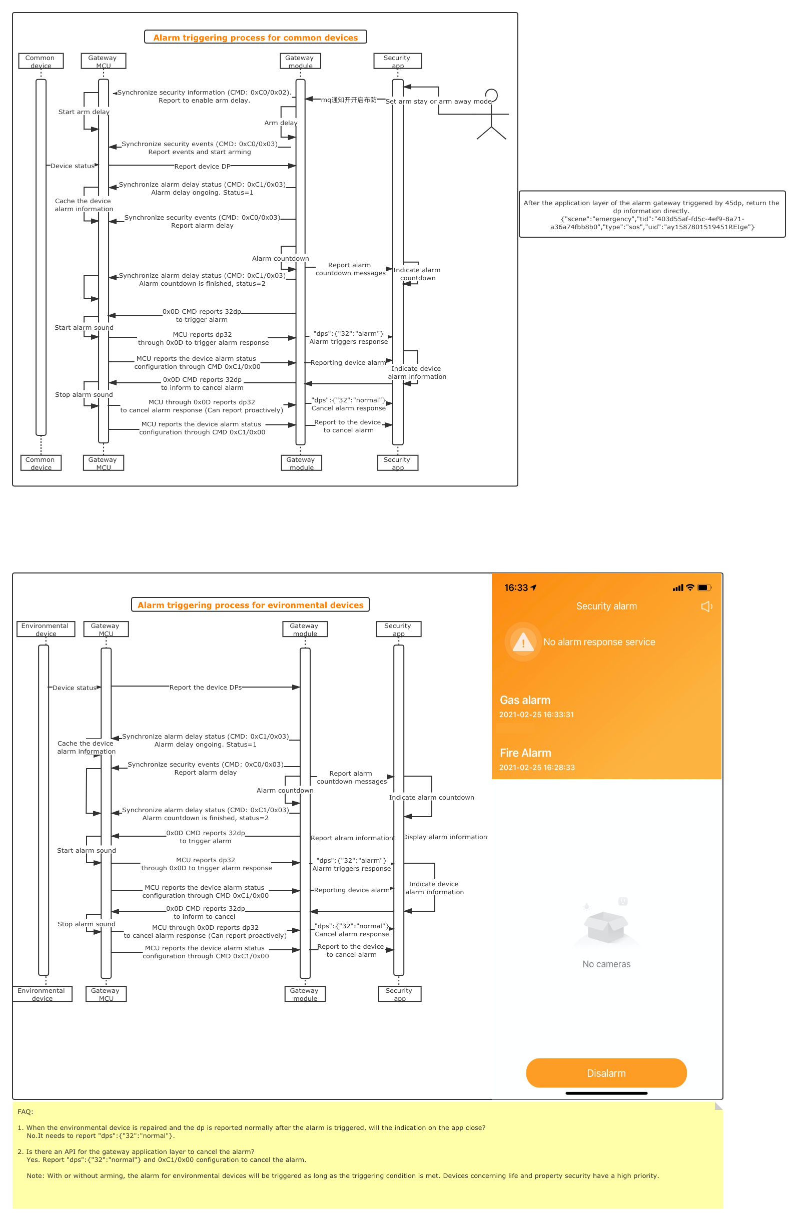
Devices trigger alarm
Contact sensors and motion sensors are common devices. When two conditions are met, if common devices detect unexpected events, the alarm will be triggered.
-
The common devices are selected as monitoring sensors on HomeSecurity.
-
Set home to arm stay or arm away mode.
-
The environmental device status can trigger alarm with or without arming.
Synchronize security information (CMD: 0xC0/0x02)
When the user sets arm or disarm on the app, the module will send the command 0xC0/0x02 to synchronize with the MCU. For the format of the command frame, see the sections about command sending in MCU Integration Protocol for Gateway.
An example of data sent from the module:
55 AA 00 C0 00 22 02 7B 22 6D 6F 64 65 22 3A 22 32 22 2C 22 64 65 6C 61 79 22 3A 33 30 2C 22 73 6F 75 6E 64 22 3A 30 7D 93
-
55 AA 00 C0 00 22: Header 0x55AA + version 0x00 + command 0xC0 + byte length of data domain 0x0022 -
02 7B 22 6D 6F 64 65 22 3A 22 32 22 2C 22 64 65 6C 61 79 22 3A 33 30 2C 22 73 6F 75 6E 64 22 3A 30 7D: Data domain. The first byte is the sub-command 0x02 and the following is the data. It is as follows after being converted into ASCII format.{"mode":"2", "delay":30, "sound":0}- "mode": Current mode. "0": disarm."1" arm stay. "2": arm away.
- "delay": Arm delay period. 0: arm delay is not set. >0: arm delay period is set, in seconds.
- "sound": whether to play a sound. 0: Enable. Others: Disable.
Reference of module data parsing code:
It indicates the code location in gw_mcu_sdk. See gw_mcu_sdk for the actual situation.
It is required to enable the definition of \#define SECURITY_PROTECTION_ENABLE in the file protocol.h to start compiling security-relevant codes.
void security_protect_infor_syn(const unsigned char p_data[], unsigned short data_len)
An example of response data from the MCU:
55 AA 00 C0 00 01 02 C2
Synchronize security events (CMD: 0xC0/0x03)
For the format of the command frame, see the sections about command sending in MCU Integration Protocol for Gateway.
The module sends synchronization status to the MCU under the following three conditions:
- The module synchronizes the current arm status to the MCU when the app or MCU sets arm or disarm. This synchronization is also performed when arm delay is not set.
- Ignorable events occur, which is used to play sound.
- If the alarm delay is set, when the status of the common devices changes, the module synchronizes to the MCU that the alarm delay starts. The unit is second.
An example of data sent from the module:
55 AA 00 C0 00 18 03 7B 22 73 74 61 74 75 73 22 3A 31 2C 22 64 61 74 61 22 3A 22 30 22 7D DD
55 AA 00 C0 00 18: Header 0x55AA + version 0x00 + command 0xC0 + byte length of data domain 0x001803 7B 22 73 74 61 74 75 73 22 3A 31 2C 22 64 61 74 61 22 3A 22 30 22 7D: Data domain. The first byte is sub-command 0x03 and the following is the data. It is as follows after being converted into ASCII format.{"status":1, "data":"0"}- "status": events. 0: disarm. 1: arm. 2: ignorable events. 3: alarm countdown starts.
- "data": This field is currently only used for alarm countdown. The value is valid when "status" = 3.
An example of response data from the MCU:
55 AA 00 C0 00 01 03 C3
Synchronize device alarm information (CMD: 0xC1/0x02)
Note: When the alarm trigger condition is met, the module will immediately send this command to synchronize the information of the alarm device to the MCU.
For the format of the command frame, see the sections about command sending in MCU Integration Protocol for Gateway.
An example of data sent from the module:
55 AA 00 C1 00 3B 02 7B 22 74 79 70 65 22 3A 30 2C 22 73 75 62 5F 69 64 22 3A 22 6D 6F 74 69 6F 6E 5F 73 65 6E 73 6F 72 5F 30 30 31 22 2C 22 64 70 5F 69 6E 66 22 3A 22 5C 22 70 69 72 5C 22 22 7D ED
-
55 AA 00 C1 00 3B: Header 0x55AA + version 0x00 + command 0xC0 + byte length of data domain 0x003B
-
02 7B 22 74 79 70 65 22 3A 30 2C 22 73 75 62 5F 69 64 22 3A 22 6D 6F 74 69 6F 6E 5F 73 65 6E 73 6F 72 5F 30 30 31 22 2C 22 64 70 5F 69 6E 66 22 3A 22 5C 22 70 69 72 5C 22 22 7D
Data domain. The first byte is sub-command 0x02 and the following is the data. It is as follows after being converted into ASCII format.
{"type":0, "sub_id":"motion_sensor_001", "dp_inf":{"1":"pir"}}- "type": Device type. 0: common device. 1: environmental device
sub_id: the device ID- "dp_inf": DP information of the alarm device, {"dpid":value}
-
The MCU first caches the device alarm information and packets the data in JSON format. When the alarm is triggered, it reports all the alarm device information with DP 26.
[{"nodeId":"motion_sensor_001", "dps":{"1":"pir"}}, ......]- The
nodeIdfield is the sub-device ID. The DPs field is the DP information of sub-device alarm.
- The
An example of response data from the MCU:
55 AA 00 C1 00 01 02 C3
Synchronize alarm delay status (CMD: 0xC1/0x03)
Note: When the alarm delay is greater than 0, if an alarm is triggered, the module will send this command twice. When the trigger condition is met, the module will immediately send this command to synchronize to the MCU that the alarm delay starts, with the value of 1. When the alarm delay ends, the module will send this command again, with the value of 2.
For the format of the command frame, see the sections about command sending in MCU Integration Protocol for Gateway.
An example of data sent from the module:
55 AA 00 C1 00 02 03 01 C6
-
55 AA 00 C1 00 02: Header 0x55AA + version 0x00 + command 0xC0 + byte length of data domain 0x0002
-
03 01: Data domain. The first byte is sub-command 0x03 and the following is the data.
0: Alarm delay is not created.
1: Alarm delay is in progress.
2: Alarm delay ends.
An example of response data from the MCU:
55 AA 00 C1 00 01 03 C4
Synchronize alarm status canceling (CMD: C1/01)
Note: After the alarm is canceled through the app, the module synchronizes the status to the MCU through this command.
For the format of the command frame, see the sections about command sending in MCU Integration Protocol for Gateway.
An example of data sent from the module:
55 AA 00 C1 00 02 01 00 C3
-
55 AA 00 C1 00 02: Header 0x55AA + version 0x00 + command 0xC0 + byte length of data domain 0x0002
-
01 00: Data domain. The first byte is sub-command 0x01 and the following is the data.
-
0: Cancel the alarm
An example of response data from the MCU:
55 AA 00 C1 00 01 01 C2
App triggers alarm
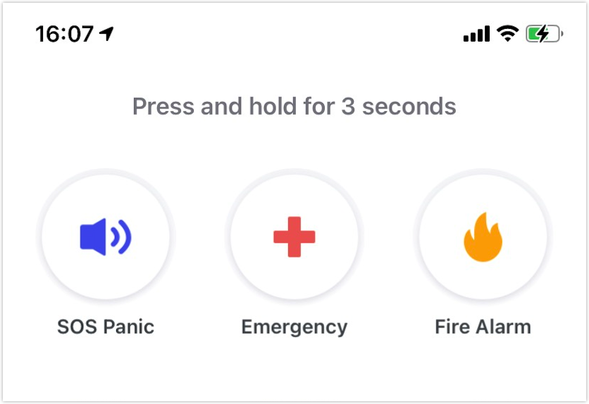
Note: As shown above, tap and hold the button on the app to trigger alarm. The module will send this message to the MCU through DP 45.
An example of serial data transmission between the module and MCU when tapping and holding the help button:
[2020-06-11, 17:37:04:657174]  The module sends: 55 AA 00 0C 00 95 04 30 30 30 30 2D 03 00 8C 65 79 4A 7A 59 32 56 75 5A 53 49 36 49 6E 42 68 62 6D 6C 6A 49 69 77 69 64 47 6C 6B 49 6A 6F 69 59 54 5A 69 4F 57 45 31 4F 44 51 74 4D 44 56 6B 4E 53 30 30 4E 32 4D 35 4C 57 4A 6A 5A 47 49 74 4E 47 5A 69 4F 47 49 32 4E 6A 55 30 4E 54 49 30 49 69 77 69 64 48 6C 77 5A 53 49 36 49 6E 4E 76 63 79 49 73 49 6E 56 70 5A 43 49 36 49 6D 46 35 4D 54 55 34 4E 6A 67 32 4E 54 63 79 4E 7A 41 30 4F 54 5A 73 4D 56 49 30 49 6E 30 3D A4  The base64 decoded data: {"scene":"panic", "tid":"a6b9a584-05d5-47c9-bcdb-4fb8b6654524", "type":"sos", "uid":"ay15868657270496l1R4"}, MCU needs only to handle the "scene" field. Help: "scene":"panic"
 Emergency: "scene":"emergency"
 Fire alarm: "scene":"fire"
 [2020-06-11, 17:37:04:663377]  MCU reports: 55 AA 00 0D 00 0A 04 30 30 30 30 20 04 00 01 01 00
 [2020-06-11, 17:37:04:664011]    MCU reports: 55 AA 00 C1 00 01 00 11 D2
 [2020-06-11, 17:37:04:664307]  MCU reports: 55 AA 00 0D 00 95 04 30 30 30 30 2D 03 00 8C 65 79 4A 7A 59 32 56 75 5A 53 49 36 49 6E 42 68 62 6D 6C 6A 49 69 77 69 64 47 6C 6B 49 6A 6F 69 59 54 5A 69 4F 57 45 31 4F 44 51 74 4D 44 56 6B 4E 53 30 30 4E 32 4D 35 4C 57 4A 6A 5A 47 49 74 4E 47 5A 69 4F 47 49 32 4E 6A 55 30 4E 54 49 30 49 69 77 69 64 48 6C 77 5A 53 49 36 49 6E 4E 76 63 79 49 73 49 6E 56 70 5A 43 49 36 49 6D 46 35 4D 54 55 34 4E 6A 67 32 4E 54 63 79 4E 7A 41 30 4F 54 5A 73 4D 56 49 30 49 6E 30 3D A5
 [2020-06-11, 17:37:04:664307]   Module responds: 55 AA 00 C1 00 01 00 00 C1
-
The DP 45 data sent from the module is encoded with basse64. The reference code of decoded data is as follows:
int iot_base64_decode( const char *base64_data, unsigned int base64_len, unsigned char *rawdata, unsigned int data_len);

 const char base64_table[] = {"ABCDEFGHIJKLMNOPQRSTUVWXYZabcdefghijklmnopqrstuvwxyz0123456789+/"}; // Convert the ASCII characters in base_table into index numbers static unsigned char base64code_convert_index(const char base64) {
 unsigned char index = 0;
 //  [0:25]: A-Z = 65-90
 if ((base64 >= 65) && (base64 <= 90)){
     index = base64-65;
 }
 // [26:51]:a-z = 97-122
 else if ((base64 >= 97) && (base64 <= 122)){
     index = base64-(97-26);
 }
 // [52:61]:0-9 = 48-57
 else if ((base64 >= 48) && (base64 <= 57)){
     index = base64 + (52-48);
 }
 else if( base64 == '+'){
     index = 62;
 }
 else if (base64 == '/'){
     index = 63;
 }
 else if (base64 == '='){
     return 0;
 }else{
     return 0xFF; // Illegal
 }

return index;
}
 /****************************************************************
 * @Function: iot_base64_encode
 * @Description: Encode the base64 string data into binary data
 * @Param: *base64_data. base64 string * @Param: base64_len. base64 string length
 * @Param: *rawdata. The first address of the binary data after being decoded.
 * @Param: data_len. The maximum number of bytes that can be written into the rawdata address space.
 * @Return: Less than 0 indicates failure. Otherwise, it returns the length of the binary data after being decoded. *****************************************************************/
 int iot_base64_decode( const char *base64_data, unsigned int base64_len, unsigned char *rawdata, unsigned int data_len)
 {
     if (base64_len%4 ! = 0){
         // printf("base64 data length is error\n");
         return -1;
     }

 // Determine the validity of parameter length to avoid memory overwrite.
     if(data_len < base64_len/4*3){
         // printf("data_len is too small\n");
         return -2;
     }

 unsigned int i,j;
     unsigned int temp = 0, actual_len = 0;
     unsigned char index[4] = {0};

 for ( i = 0, j = 0; i < base64_len; i += 4, j += 3)
     {
         index[0] = base64code_convert_index(base64_data[i]);
         index[1] = base64code_convert_index(base64_data[i+1]);
         index[2] = base64code_convert_index(base64_data[i+2]);
         index[3] = base64code_convert_index(base64_data[i+3]);
         if ((index[0] == 0xFF) || (index[1] == 0xFF) ||
             (index[2] == 0xFF) || (index[3] == 0xFF)){
             // printf("base have illegal char\n");
             return -3; // Illegal characters
         }

     // Four base characters form into three bytes which are put into the temp variable.
         temp = (index[0] << 18) | (index[1] << 12) | (index[2] << 6) | index[3];

     if ((base64_data[i+2] == '=') && (base64_data[i+3] == '=')){
             rawdata[j] = temp >> 16;
             actual_len = j+1;
         }else if(base64_data[i+3] == '='){
             rawdata[j] = temp >> 16;
             rawdata[j+1] = (temp >> 8)&0xFF;
             actual_len = j+2;
         }else{
             rawdata[j] = temp >> 16;
             rawdata[j+1] = (temp >> 8)&0xFF;
             rawdata[j+2] = temp & 0xFF;
             actual_len = j+3;
         }
     }

 return actual_len;
 }
Is this page helpful?
YesFeedbackIs this page helpful?
YesFeedback


