Basic Features
This topic describes the basic features, how it works, and commands regarding the serial communication protocol for the Wi-Fi or Wi-Fi and Bluetooth combo protocol. For more information, see Serial Communication Protocol.
The basic features include device pairing and removal, status query, and data reporting and receiving. For more information about the advanced features, see Extended Features.
Process
Main differences between v3.x.x and v2.x.x general firmware
- Added I/O validity checks. Failure to comply will cause initialization errors. Example:
- The module processes network events itself in working mode query command (
0x02): the GPIO pins used to indicate Wi-Fi status, reset the Wi-Fi network, and indicate Bluetooth LE status. - The infrared (IR) I/O pin in the product information query command (
0x01).
- The module processes network events itself in working mode query command (
- Commands must be proactively sent only after module initialization is completed (sequence:
0x00->0x01->0x02-> [0x03]). - The Wi-Fi Easy Connect (EZ) mode is disabled.
- Do not proactively send heartbeat commands after a reset. This forces the module into production test mode, blocking normal reset functionality.
- Avoid continuously sending the response to the initial heartbeat (
0x00). Doing so might trigger other proactive commands and cause exceptions. - During baud rate detection, a response must be sent within 500 ms after receiving a heartbeat probe frame. Otherwise, the baud rate cannot be locked.
For more information, see Heartbeat check.
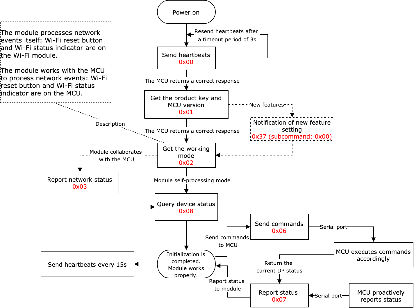
Module initialization
After the module establishes communication with the MCU, it will perform the initialization. After that, the module can exchange data with the MCU for processes such as pairing and data processing.
The initialization includes but is not limited to the following actions:
- Establishing a heartbeat connection with the MCU.
- Getting product information.
- Getting the working mode.
- Reporting the current network status to the MCU (required if the module works with the MCU to process network events).
- Getting device status.
After power on, the module keeps sending heartbeats to the MCU and will not proceed with the initialization process until receiving a correct response from the MCU.
DP format
| Field | Length (byte) | Description | |||
|---|---|---|---|---|---|
| dpid | 1 | The identifier of a DP (DP ID). | |||
| type | 1 | The data type of DP, identified by a value. | |||
| Type | Value | Length (byte) | Description | ||
| Raw | 0x00 | N | Represents a DP of raw data type. | ||
| Boolean | 0x01 | 1 | Represents a DP of Boolean data type. Valid values include 0x00 and 0x01. | ||
| Value | 0x02 | 4 | Represents a DP of integer data type, in big-endian format. | ||
| String | 0x03 | N | Represents a DP of string data type. | ||
| Enum | 0x04 | 1 | Represents a DP of enum data type, ranging from 0 to 255. | ||
| Bitmap | 0x05 | 1/2/4 | Data greater than one byte is transmitted in big-endian format. | ||
| len | 2 | The length is the number of bytes of a value. | |||
| Value | 1/2/4/N | Represented in hexadecimal format. Data greater than one byte is transmitted in big-endian format. | |||
Basic features
Heartbeat check (0x00)
-
After the Wi-Fi module is powered on, it keeps sending a heartbeat to the MCU every second and waits for a response. If the module receives a response to a heartbeat, it will send a heartbeat every 15 seconds and run the initialization command. Otherwise, the module will keep sending a heartbeat to the MCU every second until receiving a correct response.
-
The MCU can determine whether the module works properly by the regular heartbeat check. If the MCU does not receive a heartbeat packet as expected, it can use the reset pin to reset the Wi-Fi module. If the MCU fails to respond to a heartbeat within three seconds, the module considers it offline.
The module sends the following data.
| Field | Bytes | Description |
|---|---|---|
| Header | 2 | 0x55aa |
| Version | 1 | 0x00 |
| Command | 1 | 0x00 |
| Data length | 2 | 0x0000 |
| Data | 0 | None |
| Checksum | 1 | Start from the header, add up all the bytes, and then divide the sum by 256 to get the remainder. |
Example: 55 aa 00 00 00 00 ff
The MCU returns the following data.
| Field | Bytes | Description |
|---|---|---|
| Header | 2 | 0x55aa |
| Version | 1 | 0x03 |
| Command | 1 | 0x00 |
| Data length | 2 | 0x0001 |
| Data | 1 |
|
| Checksum | 1 | Start from the header, add up all the bytes, and then divide the sum by 256 to get the remainder. |
- For example, the MCU returns
55 aa 03 00 00 01 00 03after a restart. - The MCU returns
55 aa 03 00 00 01 01 04except for the first response after a restart.
Query product information (0x01)
Product information consists of the product ID and the MCU software version number.
- Product ID (PID): A unique identifier assigned to each product created on the Developer Platform for storing product information in the cloud.
- MCU software version number: It is expressed in dot-decimal notation
x.x.xwherexis a decimal digit between 0 and 99.
The module sends the following data.
| Field | Bytes | Description |
|---|---|---|
| Header | 2 | 0x55aa |
| Version | 1 | 0x00 |
| Command | 1 | 0x01 |
| Data length | 2 | 0x0000 |
| Data | 0 | None |
| Checksum | 1 | Start from the header, add up all the bytes, and then divide the sum by 256 to get the remainder. |
Example: 55 aa 00 01 00 00 00
The MCU returns the following data.
| Field | Bytes | Description |
|---|---|---|
| Header | 2 | 0x55aa |
| Version | 1 | 0x03 |
| Command | 1 | 0x01 |
| Data length | 2 | N |
| Data | N | {"p":"AIp08kLIftb8x***", "v":"1.0.0", "m":1, "mt":10, "n":0, "ir":"5.12", "low":0, "ma":[{"t":x1,"v":"y1"},{"t":x2,"v":"y2”},…], "sm":x, "wk":xx, "wkp":0, "mwk":xx, "mwkpt":50, "intr":xx} |
| Checksum | 1 | Start from the header, add up all the bytes, and then divide the sum by 256 to get the remainder. |
Example: {"p":"AIp08kLIftb8x***", "v":"1.0.0", "m":1,"mt":10,"n":0,"ir":"5.12", "low":0, "ma":[{"t":x1,"v":"y1"},{"t":x2,"v":"y2"}]}
Field description:
| Field | Description |
|---|---|
p |
Indicates the product ID is AIp08kLIftb8x***, which is the PID of a product created on the Developer Platform. |
v |
Indicates the MCU version is 1.0.0. The version number must be defined in the format x.x.x. |
m |
Indicates the working mode of the module:
|
mt |
Indicates the switching time period between the timeout pairing mode and anti-misoperation mode. You can set a period between 3 and 10 minutes. If you leave this field empty, the period defaults to 3 minutes. |
n |
Indicates the pairing mode. If you leave this field empty, the pairing mode is switched between the Wi-Fi Easy Connect (EZ) mode and the access point (AP) mode.
|
ir |
Used to enable the infrared (IR) feature and notify the module of the IR transmission (TX) pin and IR reception (RX) pin. If you leave this field empty, the IR feature is disabled. For example, 5.12 indicates the IR TX pin is I/O 5 and the IR RX pin is I/O 12.Note: If the module works in the self-processing mode, the IR I/Os must not be used for the reset button or the Wi-Fi status indicator. For cross-module I/O configuration, the pin number plus 32 makes the pin number we need. For example, the pin number to be set for PB20 is 52 (20 + 32 = 52). The IR TX pin requires PWM signals. The IR RX pin requires I/O interrupts. For more information about the pin configuration, see the datasheet of your modules.If you want to enable the IR status indicator, see (Optional) Sync new feature settings and configure it. |
low |
Used to enable the low power mode while maintaining a persistent connection. If you leave this field empty, the low power mode is disabled. In low power mode, when a device is connected to the router but not executing any commands, its power consumption can be lower than 15 mA on average. If power consumption is not your concern, you can leave this field as is.
|
(Optional) ma |
Indicates the information about the subordinate MCU. t: the channel ID, ranging from 10 to 19. v: the version number.
|
sm |
Set the sleep mode of the module in low power mode.
|
wk and wkp |
wk: indicates wake-up GPIO. When the module is in sleep mode, it is set as a wake-up GPIO, and the MCU controls the module wake-up. The falling edge is active by default. wkp: indicates the wake-up method. 0: Falling edge active. 1: Rising edge active. If you leave this field empty, the falling edge active is used by default. |
mwk and mwkpt |
|
intr |
Ethernet port interrupt GPIO. When data arrives from the Ethernet, the module can be notified through this GPIO. |
The value of ma must be consistent with the value of Update Channel specified on the Developer Platform. Otherwise, the device may not receive any updates or may receive incorrect ones.
(Optional) Sync new feature settings (0x37 & 0x00)
- After the device is powered on, the MCU sends this command to notify the module of feature settings after the command
0x01and before the command0x02. - If no new feature settings are required, the MCU does not need to send this command.
- The MCU must send this command each time after the module is powered on or restarted and sends
0x01. - The fields of this command will be added as the service is extended.
ir: IR status indicator. It can share the same GPIO pin with the Wi-Fi status indicator but must not conflict with other GPIOs associated with the command0x02. The IR status indicator is defined as follows.- Sharing the same GPIO pin with the Wi-Fi status indicator: The LED is on when the IR is idle. The LED is off when the IR is used.
- Using an individual GPIO pin: The LED is on when the IR is used. The LED is off when the IR is idle.
buf: The maximum buffer size of the MCU serial port. For the RF remote control feature, when multiple key values are transmitted, this field determines whether packet fragmentation is needed.b_nm: The local name of Bluetooth, up to five bytes long.w_max: The maximum interval for Wi-Fi reconnection, ranging from 1 minute to 30 minutes.- RF remote control: The 433 MHz RF remote controls developed with the Tuya standard RF solution.
The MCU sends the following data.
| Field | Bytes | Description |
|---|---|---|
| Header | 2 | 0x55aa |
| Version | 1 | 0x03 |
| Command | 1 | 0x37 |
| Data length | 2 | 0x0001 |
| Data | 1 | Subcommand: 0x00 |
{ "mcu_ota":xx, "abv":x, "ir":xx, "buf":xx, "b_nm":"xx", "w_max":xx} |
ir: sets the GPIO pin used for the IR status indicator in the module self-processing mode. The data content follows the definition of the command 0x02. For more information, see IR feature.buf: the MCU serial receive buffer, with a minimum size of 256 bytes. If the buffer size is not specified, the module considers the MCU can receive data of any length.b_nm: the local name of Bluetooth, up to five bytes long.w_max: the maximum interval for Wi-Fi reconnection, ranging from 1 minute to 30 minutes. |
|
| Checksum | 1 | Start from the header, add up all the bytes, and then divide the sum by 256 to get the remainder. |
Example: If the MCU has a scratchpad, the RF remote control is enabled, and the buffer size is 1,024 bytes, the MCU sends the following data.
{"mcu_ota":0,"abv":3,"buf":1024}
55 aa 03 37 00 21 00 7b 22 6d 63 75 5f 6f 74 61 22 3a 30 2c 22 61 62 76 22 3a 33 2c 22 62 75 66 22 3a 31 30 32 34 7d ac
The module returns the following data.
| Field | Bytes | Description |
|---|---|---|
| Header | 2 | 0x55aa |
| Version | 1 | 0x00 |
| Command | 1 | 0x37 |
| Data length | 2 | 0x0002 |
| Data | 1 | Subcommand: 0x00 |
| 1 | Ret:
|
|
| Checksum | 1 | Start from the header, add up all the bytes, and then divide the sum by 256 to get the remainder. |
Example: 55 aa 03 37 00 02 00 00 3b
Field description:
| Field | Required | Description |
|---|---|---|
mcu_ota |
Optional | Specifies whether an MCU has a scratchpad. This field only applies to HomeKit accessories currently. |
abv |
Optional | Enables new features. Each bit represents a feature.
|
ir |
Optional | Sets the GPIO pin used for the IR status indicator in the module self-processing mode. The GPIO pin definition is the same as the command 0x02. For example, 5 indicates the pin for the IR status indicator is I/O5. |
buf |
Optional | The MCU serial receive buffer, with a minimum size of 256 bytes. |
Query working mode (0x02)
The MCU specifies the pairing trigger and status indicator. The working mode indicates how the Wi-Fi network status is indicated and the way to trigger module reset.
-
The MCU works with the module to process network events.
When the MCU detects a pairing signal, it instructs the module to reset. The module sends its current Wi-Fi status to the MCU through the serial port. The MCU controls the LED to indicate status accordingly. Home appliances usually use this mode.
-
The module processes network events itself.
The GPIO pin on the module drives the LED indicator to indicate the network status. The GPIO input signal determines module reset.
When the module detects a low level on the reset pin for more than five seconds, it will trigger a reset action. The following command specifies the GPIO pins of the LED indicator and the reset button.
The module sends the following data.
| Field | Bytes | Description |
|---|---|---|
| Header | 2 | 0x55aa |
| Version | 1 | 0x00 |
| Command | 1 | 0x02 |
| Data length | 2 | 0x0000 |
| Data | 0 | None |
| Checksum | 1 | Start from the header, add up all the bytes, and then divide the sum by 256 to get the remainder. |
Example: 55 aa 00 02 00 00 01
The MCU returns the following data.
| Field | Bytes | Description |
|---|---|---|
| Header | 2 | 0x55aa |
| Version | 1 | 0x03 |
| Command | 1 | 0x02 |
| Data length | 2 |
|
| Data | 0/2/3 | If the data length is two bytes:
|
| Checksum | 1 | Start from the header, add up all the bytes, and then divide the sum by 256 to get the remainder. |
Example:
-
The MCU works with the module to process network events.
55 aa 03 02 00 00 04 -
The module processes network events itself:
0x0cindicates the LED indicator is connected to GPIO12.0x0dindicates the reset button is connected to GPIO13.55 aa 03 02 00 02 0c 0d 1f
Report network status (0x03)
| Network status | Description | Status value |
|---|---|---|
| Status 1 | Pairing in EZ mode (For Wi-Fi and Bluetooth LE combo module: Bluetooth is also in pairing mode.) | 0x00 |
| Status 2 | Pairing in AP mode (For Wi-Fi and Bluetooth LE combo module: Bluetooth is also in pairing mode.) | 0x01 |
| Status 3 | The Wi-Fi network is set up, but the device is not connected to the router. | 0x02 |
| Status 4 | The Wi-Fi network is set up, and the device is connected to the router. | 0x03 |
| Status 5 | The device is connected to the cloud. | 0x04 |
| Status 6 | The main network module is in low power mode. | 0x05 |
| Status 7 | EZ mode and AP mode coexist. (For Wi-Fi and Bluetooth LE combo module: Bluetooth is also in pairing mode.) | 0x06 |
-
Network status
- Pairing in EZ mode (For Wi-Fi and Bluetooth LE combo module: Bluetooth is also in pairing mode.)
- Pairing in AP mode (For Wi-Fi and Bluetooth LE combo module: Bluetooth is also in pairing mode.)
- The Wi-Fi network is set up, but the device is not connected to the router.
- The Wi-Fi network is set up, and the device is connected to the router.
- The device is connected to the cloud.
-
The LED activity in the module self-processing mode.
- Status 1: blinking every 250 ms.
- Status 2: blinking every 1,500 ms.
- Status 3 or 6: steady off.
- Status 4 or 5: steady on.
-
When the module detects that the MCU is restarted or reconnected, it will proactively send the current Wi-Fi status to the MCU.
-
When the network status changes, the module will proactively send its current status to the MCU.
-
If you choose the module self-processing mode, implementing this protocol for your MCU is not necessary.
- For devices using the Wi-Fi and Bluetooth LE combo module, when the network status is
0x00,0x01, or0x06, Bluetooth is also in pairing mode. - Network status
0x04indicates a device is successfully paired either over Wi-Fi or Bluetooth. If the device is paired over Bluetooth, check its Bluetooth status to see if it can be controlled using the mobile app. - It is recommended to subscribe to Bluetooth connection status to notify users of the current Bluetooth status.
The module sends the following data.
| Field | Bytes | Description |
|---|---|---|
| Header | 2 | 0x55aa |
| Version | 1 | 0x00 |
| Command | 1 | 0x03 |
| Data length | 2 | 0x0001 |
| Data | 1 | Valid values that represent the Wi-Fi network status:
|
| Checksum | 1 | Start from the header, add up all the bytes, and then divide the sum by 256 to get the remainder. |
Example: 55 aa 00 03 00 01 00 03
The MCU returns the following data.
| Field | Bytes | Description |
|---|---|---|
| Header | 2 | 0x55aa |
| Version | 1 | 0x03 |
| Command | 1 | 0x03 |
| Data length | 2 | 0x0000 |
| Data | 0 | None |
| Checksum | 1 | Start from the header, add up all the bytes, and then divide the sum by 256 to get the remainder. |
Example: 55 aa 03 03 00 00 05
Reset Wi-Fi (0x04)
When receiving a reset command, the module will restart, perform the initialization, and enter the pairing mode.
The following figure shows how the Wi-Fi state changes after a reset.
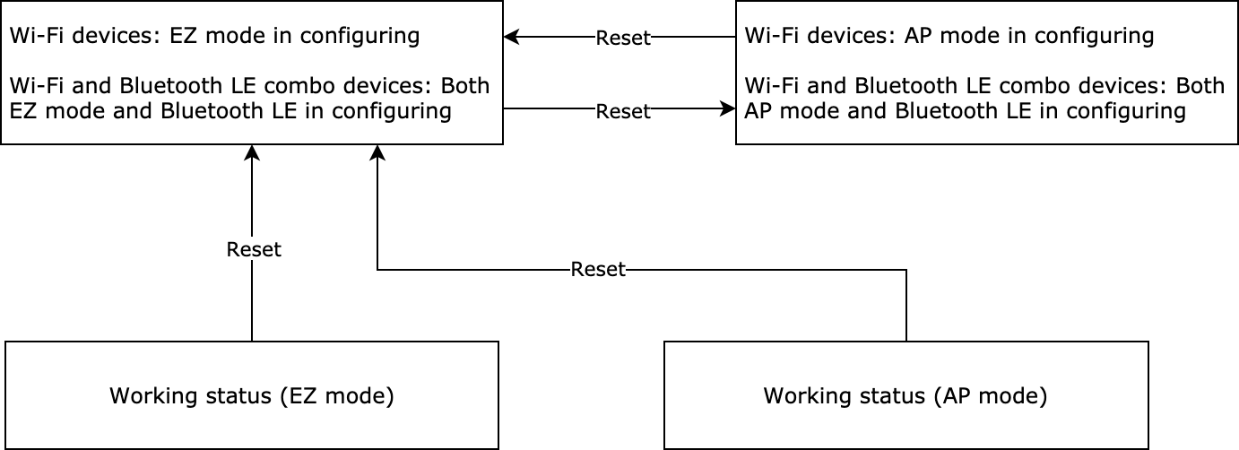
- The reset command must be sent after the module initialization is completed. Otherwise, the reset might not work. For more information, see Module initialization.
- When a combo module receives a reset command, both its Wi-Fi and Bluetooth will enter pairing mode.
If you choose the module self-processing mode, implementing this protocol for your MCU is not necessary.
When the module detects a low level on the reset pin for more than five seconds, it will trigger a reset action.
The MCU sends the following data.
| Field | Bytes | Description |
|---|---|---|
| Header | 2 | 0x55aa |
| Version | 1 | 0x03 |
| Command | 1 | 0x04 |
| Data length | 2 | 0x0000 |
| Data | 0 | None |
| Checksum | 1 | Start from the header, add up all the bytes, and then divide the sum by 256 to get the remainder. |
Example: 55 aa 03 04 00 00 06
The module returns the following data.
| Field | Bytes | Description |
|---|---|---|
| Header | 2 | 0x55aa |
| Version | 1 | 0x00 |
| Command | 1 | 0x04 |
| Data length | 2 | 0x0000 |
| Data | 0 | None |
| Checksum | 1 | Start from the header, add up all the bytes, and then divide the sum by 256 to get the remainder. |
Example: 55 aa 00 04 00 00 03
Reset Wi-Fi and select pairing mode (0x05)
This command is similar to the previous Wi-Fi reset command.
-
Compared to Reset Wi-Fi, this command enables the MCU to select the pairing mode after a reset.
-
You can implement this protocol as needed.
-
If you choose the module self-processing mode, implementing this protocol for your MCU is not necessary.
- The reset command must be sent after the module initialization is completed. Otherwise, the reset might not work. For more information, see Module initialization.
- If the MCU sets the
nfield in response to the product information query, the mode specified by this command will not work.
The MCU sends the following data.
| Field | Bytes | Description |
|---|---|---|
| Header | 2 | 0x55aa |
| Version | 1 | 0x03 |
| Command | 1 | 0x05 |
| Data length | 2 | 0x0001 |
| Data | 1 |
|
| Checksum | 1 | Start from the header, add up all the bytes, and then divide the sum by 256 to get the remainder. |
For example, the MCU sends the following data to specify the EZ mode.
55 aa 03 05 00 01 00 08
The module returns the following data.
| Field | Bytes | Description |
|---|---|---|
| Header | 2 | 0x55aa |
| Version | 1 | 0x00 |
| Command | 1 | 0x05 |
| Data length | 2 | 0x0000 |
| Data | 0 | None |
| Checksum | 1 | Start from the header, add up all the bytes, and then divide the sum by 256 to get the remainder. |
Example: 55 aa 00 05 00 00 04
Factory reset (0xF4)
After the MCU sends this command and the device enters pairing, the device ID will change.
The MCU sends the following data.
| Field | Bytes | Description |
|---|---|---|
| Header | 2 | 0x55aa |
| Version | 1 | 0x03 |
| Command | 1 | 0xF4 |
| Data length | 2 | 0x0000 |
| Data | 0 | None |
| Checksum | 1 | Start from the header, add up all the bytes, and then divide the sum by 256 to get the remainder. |
The module returns the following data.
| Field | Bytes | Description |
|---|---|---|
| Header | 2 | 0x55aa |
| Version | 1 | 0x00 |
| Command | 1 | 0xF4 |
| Data length | 2 | 0x0000 |
| Data | 0 | None |
| Checksum | 1 | Start from the header, add up all the bytes, and then divide the sum by 256 to get the remainder. |
Enable reset status notification (0x34 04)
The module supports local reset, reset via the app, and factory reset.
The MCU sends the following data.
| Field | Bytes | Description |
|---|---|---|
| Header | 2 | 0x55aa |
| Version | 1 | 0x03 |
| Command | 1 | 0x034 |
| Data length | 2 | 0x0001 |
| Data | 1 | 0x04 (subcommand) |
| Checksum | 1 | Start from the header, add up all the bytes, and then divide the sum by 256 to get the remainder. |
The module returns the following data.
| Field | Bytes | Description |
|---|---|---|
| Header | 2 | 0x55aa |
| Version | 1 | 0x00 |
| Command | 1 | 0x034 |
| Data length | 2 | 0x0002 |
| Data | 1 | 0x04 (subcommand) |
| 1 | Result:
|
|
| Checksum | 1 | Start from the header, add up all the bytes, and then divide the sum by 256 to get the remainder. |
Notify the MCU of reset status (0x34 05)
The module sends the following data.
| Field | Bytes | Description |
|---|---|---|
| Header | 2 | 0x55aa |
| Version | 1 | 0x00 |
| Command | 1 | 0x034 |
| Data length | 2 | 0x0002 |
| Data | 1 | 0x05 (subcommand) |
| 1 | Reset status
|
|
| Checksum | 1 | Start from the header, add up all the bytes, and then divide the sum by 256 to get the remainder. |
The MCU returns the following data.
| Field | Bytes | Description |
|---|---|---|
| Header | 2 | 0x55aa |
| Version | 1 | 0x03 |
| Command | 1 | 0x034 |
| Data length | 2 | 0x0001 |
| Data | 1 | 0x05 (subcommand) |
| Checksum | 1 | Start from the header, add up all the bytes, and then divide the sum by 256 to get the remainder. |
Send commands (0x06)
- The command sending is processed asynchronously. The module parses the received data and sends it to the MCU. The MCU executes the command accordingly and reports the changed DP status if required.
- One command can contain data units of multiple DPs.
The module sends the following data.
| Field | Bytes | Description |
|---|---|---|
| Header | 2 | 0x55aa |
| Version | 1 | 0x00 |
| Command | 1 | 0x06 |
| Data length | 2 | It depends on the type and the number of DPs. |
| Data | N | The DP data set. |
| Checksum | 1 | Start from the header, add up all the bytes, and then divide the sum by 256 to get the remainder. |
Suppose that DP 3 of Boolean type is used for on/off control, and 1 means to turn on the device. The module sends the following to the MCU.
55 aa 00 06 00 05 03 01 00 01 01 10
Report status (async) (0x07)
-
This is an asynchronous command. The MCU uses it to report DP status to the module, which can be triggered by three mechanisms.
- After the MCU executes the command received from the module, it reports the changed DP status to the module.
- When the MCU proactively detects status changes of DPs, it reports the changed DP status to the module.
- When the MCU receives the DP status query, it sends the status of all DPs to the module.
-
A piece of status data can contain data units of multiple DPs. If raw DPs are included, each raw DP is reported as a separate record, while the other DPs are combined into one record. The total number of reported DP records equals the number of raw DPs plus one.
- It is recommended to report the status of a DP when it is changed to ensure stable data transmission. Try to avoid frequent status reporting for a short period of time.
- When the device is in the idle or stable state, make sure the frequency of reporting the status of the same DP is appropriate. The recommended minimum interval is one minute.
- The DP that the MCU reports must match the PID’s DP defined on the Developer Platform. The PID is the value of the
pfield that the MCU returns on the product information query. The MCU must not report any DP that does not exist. - The DP ID, data type, and payload that the MCU reports must match the PID’s DP defined on the Developer Platform. The PID is the value of the
pfield that the MCU returns on the product information query.
The MCU sends the following data.
| Field | Bytes | Description |
|---|---|---|
| Header | 2 | 0x55aa |
| Version | 1 | 0x03 |
| Command | 1 | 0x07 |
| Data length | 2 | It depends on the type and the number of DPs. |
| Data | N | The DP data set. |
| Checksum | 1 | Start from the header, add up all the bytes, and then divide the sum by 256 to get the remainder. |
Example:
-
Suppose that DP 5 of a value type describes the humidity. When the current humidity is 30%, the MCU reports the following data.
55 aa 03 07 00 08 05 02 00 04 00 00 00 1e 3a -
Report multiple DPs
-
The DP 109 is of Boolean data type, and its value is
1. -
The DP 102 is of string data type, and its value is
201804121507that is transferred in ASCII mode. The MCU sends the following data.55 aa 03 07 00 15 6d 01 00 01 01 66 03 00 0c 32 30 31 38 30 34 31 32 31 35 30 37 62
-
Report status (sync) (0x022)
-
It is not recommended to use this command to report non-statistical DPs, as this command has no DP cache.
-
This is a synchronous command. The MCU reports DP status and then waits for the result from the module.
-
The module responds to each status reporting message. The MCU should not send a new request until receiving a response to the previous status reporting.
-
If the data fails to be reported to the cloud due to poor network quality, the module will return a failure code five seconds later. In this case, the MCU should wait for more than five seconds.
-
A piece of status data can contain data units of multiple DPs. If raw DPs are included, each raw DP is reported as a separate record, while the other DPs are combined into one record. The total number of reported DP records equals the number of raw DPs plus one.
- It is recommended to report the status of a DP when it is changed to ensure stable data transmission. Try to avoid frequent status reporting for a short period of time.
- If you have multiple DPs to report, it is recommended to report them in one packet. For reporting a single DP, set the reporting interval to at least 250 milliseconds for stable data transmission.
- When the device is in the idle or stable state, make sure the frequency of reporting the status of the same DP is appropriate. The recommended minimum interval is one minute.
- The DP that the MCU reports must match the PID’s DP defined on the Developer Platform. The PID is the value of the
pfield that the MCU returns on the product information query. The MCU must not report any DP that does not exist. - The DP ID, data type, and payload that the MCU reports must match the PID’s DP defined on the Developer Platform. The PID is the value of the
pfield that the MCU returns on the product information query.
The MCU sends the following data.
| Field | Bytes | Description |
|---|---|---|
| Header | 2 | 0x55aa |
| Version | 1 | 0x03 |
| Command | 1 | 0x22 |
| Data length | 2 | It depends on the type and the number of DPs. |
| Data | N | The DP data set. |
| Checksum | 1 | Start from the header, add up all the bytes, and then divide the sum by 256 to get the remainder. |
For example, the status of Boolean DP 1 is true. The MCU reports the following data to the module:
55 aa 03 22 00 05 02 01 00 01 01 2e
The module returns the following data.
| Field | Bytes | Description |
|---|---|---|
| Header | 2 | 0x55aa |
| Version | 1 | 0x00 |
| Command | 1 | 0x23 |
| Data length | 2 | 0x0001 |
| Data | Data |
|
| Checksum | 1 | Start from the header, add up all the bytes, and then divide the sum by 256 to get the remainder. |
Example: 55 aa 00 23 00 01 01 24
Report status (record-type) (0x34 & 0x0b)
-
This is a synchronous command. The MCU reports DP status and then waits for the result from the module.
-
The module responds to each status reporting message. The MCU should not send a new request until receiving a response to the previous status reporting.
-
If the data fails to be reported to the cloud due to poor network quality, the module will return a failure code five seconds later. In this case, the MCU should wait for more than five seconds.
-
A piece of status data can contain data units of multiple DPs.
-
For devices with records or metering features, such as door locks and smart plugs with energy monitoring, you can use this command to report the status of the corresponding DPs. If a single record message contains the status of multiple DPs, it should be reported in one packet.
-
This type of status reporting only applies to the Wi-Fi protocol currently. The Bluetooth protocol support for this type of status reporting will be added in the firmware update in the future.
-
In low power sleep mode (the product information contains an
smfield), the module will cache failed DPs in the flash memory and report them until the next time the MCU triggers a record-type DP reporting. -
Before using this type of status reporting, check if the current firmware supports it.
- The module does not cache the data that fails to be reported.
- It is recommended to report the status of a DP when it is changed to ensure stable data transmission. Try to avoid frequent status reporting for a short period of time.
- If you have multiple DPs to report, it is recommended to report them in one packet. For reporting a single DP, set the reporting interval to at least 250 milliseconds for stable data transmission.
- When the device is in the idle or stable state, make sure the frequency of reporting the status of the same DP is appropriate. The recommended minimum interval is one minute.
- The DP that the MCU reports must match the PID’s DP defined on the Developer Platform. The PID is the value of the
pfield that the MCU returns on the product information query. The MCU must not report any DP that does not exist. - The DP ID, data type, and payload that the MCU reports must match the PID’s DP defined on the Developer Platform. The PID is the value of the
pfield that the MCU returns on the product information query.
The MCU sends the following data.
| Field | Length | Description |
|---|---|---|
| Header | 2 | 0x55aa |
| Version | 1 | 0x03 |
| Command | 1 | 0x34 |
| Data length | 2 | It depends on the type and the number of DPs. |
| Data | 1 | 0x0b (subcommand) |
| 1 | 0x01 (default) | |
| 1 | The time data carried in the payload:
|
|
| 6 | Date and time format:
|
|
| N | Data units | |
| Checksum | 1 | Start from the header, add up all the bytes, and then divide the sum by 256 to get the remainder. |
Example 1: for the Boolean DP of DP ID 1, if its status is true, and the GMT is 2022.02.18.16:27:06, the MCU reports 55 aa 03 34 00 0e 0b 01 02 16 02 12 10 1b 06 01 01 00 01 01 b1to the module. Example 2: for the value DP of DP ID 2, its status is100; and for the enum DP of DP ID 3, its status is 3. If the local time is 2022.02.22.11:22:33, the MCU reports 55 aa 03 34 00 16 0b 01 01 16 02 16 0b 16 21 02 02 00 04 00 00 00 64 03 04 00 01 03 40 to the module.
The module returns the following data.
| Field | Length | Description |
|---|---|---|
| Header | 2 | 0x55aa |
| Version | 1 | 0x00 |
| Command | 1 | 0x34 |
| Data length | 2 | 0x0002 |
| Data | 1 | 0x0b (subcommand) |
| 1 | The result of status reporting:
|
|
| Checksum | 1 | Start from the header, add up all the bytes, and then divide the sum by 256 to get the remainder. |
Example: 55 aa 00 34 00 02 0b 00 40
Get cached DP command (0x90)
For sensors that can control other devices, you need to implement DP sending functions. When the device is offline, commands will be cached in the cloud, waiting for the device to retrieve them. Once a cached command is retrieved, it will not be sent again if requested again.
The MCU sends the following data.
| Field | Bytes | Description |
|---|---|---|
| Header | 2 | 0x55aa |
| Version | 1 | 0x03 |
| Command | 1 | 0x90 |
| Data length | 2 | N |
| Data | dp_num (1 byte) + dp_1 (1 byte)+ … + dp_n (1 byte) |
If dp_num is 0, all DPs will be queried. |
| Checksum | 1 | Start from the header, add up all the bytes, and then divide the sum by 256 to get the remainder. |
Example: 55 AA 03 90 00 01 00 93
The module returns the following data.
| Field | Bytes | Description |
|---|---|---|
| Header | 2 | 0x55aa |
| Version | 1 | 0x00 |
| Command | 1 | 0x90 |
| Data length | 2 | It depends on the type and the number of DPs. |
| Data | result (1 byte) + dp_num (1 byte) + dp_1 (n byte) + … + dp_n(n byte) |
The DP data with cached commands.
|
| Checksum | 1 | Start from the header, add up all the bytes, and then divide the sum by 256 to get the remainder. |
Example: No cached DP data, 55 AA 00 90 00 02 01 00 92
Query status (0x08)
-
The module asynchronously queries the status of all object-type DPs from the MCU. When the MCU receives a query, it reports the status of the respective DP.
-
The module sends a status query to the MCU when the following three events occur.
- When powered on for the first time, the module sends a status query after it connects to the MCU.
- When the module detects the MCU is restarted or reconnected, the module sends a status query. This requires the MCU to enable bit 3 in the
advfield through the command0x3700. - When the device is connected over Wi-Fi, a status query will be triggered upon the user opening the app panel. This requires the MCU to enable bit 3 in the
advfield through the command0x3700.
- Check firmware compatibility with this feature. Update to the latest firmware version if necessary.
- The legacy firmware only supports sending status queries when the device is powered on for the first time.
The module sends the following data.
| Field | Bytes | Description |
|---|---|---|
| Header | 2 | 0x55aa |
| Version | 1 | 0x00 |
| Command | 1 | 0x08 |
| Data length | 2 | 0x0000 |
| Data | 0 | None |
| Checksum | 1 | Start from the header, add up all the bytes, and then divide the sum by 256 to get the remainder. |
Example: 55 aa 00 08 00 00 07
Get module’s memory (0x0f)
Get the remaining memory of the Wi-Fi module.
The MCU sends the following data.
| Field | Bytes | Description |
|---|---|---|
| Header | 2 | 0x55aa |
| Version | 1 | 0x03 |
| Command | 1 | 0x0f |
| Data length | 2 | 0x0000 |
| Data | Data | None |
| Checksum | 1 | Start from the header, add up all the bytes, and then divide the sum by 256 to get the remainder. |
Example: 55 aa 03 0f 00 00 11
The module returns the following data.
| Field | Bytes | Description |
|---|---|---|
| Header | 2 | 0x55aa |
| Version | 1 | 0x00 |
| Command | 1 | 0x0f |
| Data length | 2 | 0x0004 |
| Data | 4 | The value is represented in big-endian format. For example, 0x00 0x00 0x28 0x00 represents 10,240 bytes of remaining memory. |
| Checksum | 1 | Start from the header, add up all the bytes, and then divide the sum by 256 to get the remainder. |
For example, if the remaining memory size is 53,328 bytes, the module returns 55 aa 00 0f 00 04 50 d0 00 00 32.
(Optional) Get signal strength (0x24)
The MCU sends the following data.
| Field | Bytes | Description |
|---|---|---|
| Header | 2 | 0x55aa |
| Version | 1 | 0x03 |
| Command | 1 | 0x24 |
| Data length | 2 | 0 |
| Data | N | None |
| Checksum | 1 | Start from the header, add up all the bytes, and then divide the sum by 256 to get the remainder. |
Example: 55 aa 03 24 00 00 26
The module returns the following data.
| Field | Bytes | Description |
|---|---|---|
| Header | 2 | 0x55aa |
| Version | 1 | 0x00 |
| Command | 1 | 0x24 |
| Data length | 2 | 0x0001 |
| Data | Data |
|
| Checksum | 1 | Start from the header, add up all the bytes, and then divide the sum by 256 to get the remainder. |
For example, if the value of RSSI is -20 dB, the module returns 55 aa 00 24 00 01 ec 10.
(Optional) Disable heartbeats (0x25)
The MCU sends the following data.
| Field | Bytes | Description |
|---|---|---|
| Header | 2 | 0x55aa |
| Version | 1 | 0x03 |
| Command | 1 | 0x25 |
| Data length | 2 | 0 |
| Data | N | None |
| Checksum | 1 | Start from the header, add up all the bytes, and then divide the sum by 256 to get the remainder. |
Example: 55 aa 03 25 00 00 27
The module returns the following data.
| Field | Bytes | Description |
|---|---|---|
| Header | 2 | 0x55aa |
| Version | 1 | 0x00 |
| Command | 1 | 0x25 |
| Data length | 2 | 0 |
| Data | N | None |
| Checksum | 1 | Start from the header, add up all the bytes, and then divide the sum by 256 to get the remainder. |
Example: 55 aa 00 25 00 00 24
Before the module goes to sleep to reduce power consumption, the MCU can send this command to notify the module to disable the heartbeat. Because heartbeats are required for building communication between the module and the MCU, this command must not be sent when the device is just powered on.
(Optional) Pair via serial port (0x2a)
- If your device pairing solution is implemented by the communication between the mobile app and the module, implementing this command is not necessary.
- This command applies to local pairing. You can get the pairing information from the mobile app and send it to the module through serial communication to complete the pairing.
- To be paired via serial port, the module must be in the pairing mode.
- The module will use the received information to connect to the router and register in the cloud.
The MCU sends the following data.
| Field | Bytes | Description |
|---|---|---|
| Header | 2 | 0x55aa |
| Version | 1 | 0x03 |
| Command | 1 | 0x2A |
| Data length | 2 | xx |
| Data | Data | {"s":"xxx", "p":"yyy", "t":"zzz"}
|
| Checksum | 1 | Start from the header, add up all the bytes, and then divide the sum by 256 to get the remainder. |
Example: {"s":"xxx", "p":"12345678", "t":"zzz"}
55 aa 03 2a 00 24 7b 22 73 22 3a 22 78 78 78 22 2C 22 70 22 3a 22 31 32 33 34 35 36 37 38 22 2c 22 74 22 3a 22 7a 7a 7a 22 7d B7
The module returns the following data.
| Field | Bytes | Description |
|---|---|---|
| Header | 2 | 0x55aa |
| Version | 1 | 0x00 |
| Command | 1 | 0x2A |
| Data length | 2 | 0x0001 |
| Data | x |
|
| Checksum | 1 | Start from the header, add up all the bytes, and then divide the sum by 256 to get the remainder. |
Example: 55 aa 00 2a 00 01 01 2b
Request network status (0x2b)
| Network status | Description | Status value |
|---|---|---|
| Status 1 | Pairing in EZ mode (For Wi-Fi and Bluetooth LE combo module: Bluetooth is also in pairing mode.) | 0x00 |
| Status 2 | Pairing in AP mode (For Wi-Fi and Bluetooth LE combo module: Bluetooth is also in pairing mode.) | 0x01 |
| Status 3 | The Wi-Fi network is set up, but the device is not connected to the router. | 0x02 |
| Status 4 | The Wi-Fi network is set up, and the device is connected to the router. | 0x03 |
| Status 5 | The device is connected to the cloud. | 0x04 |
| Status 6 | The main network module is in low power mode. | 0x05 |
| Status 7 | EZ mode and AP mode coexist. (For Wi-Fi and Bluetooth LE combo module: Bluetooth is also in pairing mode.) | 0x06 |
The status definition must be consistent with that in Report network status.
The MCU sends the following data.
| Field | Bytes | Description |
|---|---|---|
| Header | 2 | 0x55aa |
| Version | 1 | 0x03 |
| Command | 1 | 0x2B |
| Data length | 2 | 0x0000 |
| Data | Data | None |
| Checksum | 1 | Start from the header, add up all the bytes, and then divide the sum by 256 to get the remainder. |
Example: 55 aa 03 2b 00 00 2d
The module returns the following data.
| Field | Bytes | Description |
|---|---|---|
| Header | 2 | 0x55aa |
| Version | 1 | 0x00 |
| Command | 1 | 0x2B |
| Data length | 2 | 0x0001 |
| Data | 1 |
|
| Checksum | 1 | Start from the header, add up all the bytes, and then divide the sum by 256 to get the remainder. |
For example, if the device is connected to the router and the cloud, the module returns 55 aa 00 2b 00 01 04 2f.
Get module’s MAC address (0x2d)
The MCU sends the following data.
| Field | Bytes | Description |
|---|---|---|
| Header | 2 | 0x55aa |
| Version | 1 | 0x03 |
| Command | 1 | 0x2d |
| Data length | 2 | 0x0000 |
| Data | Data | None |
| Checksum | 1 | Start from the header, add up all the bytes, and then divide the sum by 256 to get the remainder. |
Example: 55 aa 03 2d 00 00 2f
The module returns the following data.
| Field | Bytes | Description |
|---|---|---|
| Header | 2 | 0x55aa |
| Version | 1 | 0x00 |
| Command | 1 | 0x2d |
| Data length | 2 | 0x0007 |
| Data | Data |
|
| Checksum | 1 | Start from the header, add up all the bytes, and then divide the sum by 256 to get the remainder. |
Example: The MAC address is 508A0E3A2D9.
55 aa 00 2d 00 07 00 50 8a 06 e3 a2 d9 71
Get module information (0x3407)
Compliance reminders
Collecting this information is voluntary on your part. Your Privacy Policy should clearly state the following:
- Data collection: Declare who will collect this information, which may be you or a third-party service provider.
- Purpose of data usage: Detail how this information will be used, including its purpose and whether it will be shared with other parties.
- Data retention: State how long the information will be kept and the security measures in place for data retention.
Description:
- The running data of the Wi-Fi module is required for some products.
0x3407is used to get the required information. - The MCU can send a specified code to the module to get the required information. If the MCU requires multiple types of information, the codes must be sent in order.
- If the MCU requires all the information available, it can use the code
0xff. - If the SSID of an AP is the default
SmartLife, this command only returnsSmartLife. The actual SSID isSmartLife_XXXX.XXXXrepresents the last four digits of the MAC address.
Considerations:
-
The return data format is JSON and the
datalength varies depending on the information type. -
The length of data that the MCU sends to the module must be at least two bytes, namely the subcommand plus a 1-byte
datacode. If the data length is incorrect, the module will return a failure. -
The data codes have a one-to-one relationship with the information types. Make sure you use the correct data code and do not use the reserved code.
Name Code All the information available 0xff AP’s SSID 0x01 Country code 0x02 Serial number (SN) 0x03 Frustration-Free Setup (FFS) authorization 0x04 Module’s version number 0x05 Wi-Fi configurations 0x06 Universally unique identifier (UUID) 0x07
Description of return values
| Field | Name | Options | Get | Set |
|---|---|---|---|---|
| ap | AP’s SSID | String | Supported | Not supported |
| cc | Country code |
|
Supported | Not supported |
| sn | Serial number (SN) | The SN written to the module after authorization. | Not supported | Not supported |
| ffs | Frustration-Free Setup (FFS) authorization |
|
Not supported | Not supported |
| sw | Module version | The version number is formatted as x.x.x. |
Supported | Not supported |
| wcfg | Wi-Fi configurations |
|
Supported | Not supported |
| uuid | Universally unique identifier (UUID) | The UUID information that is written during authorization. | Supported | Not supported |
- The common Wi-Fi modules do not support getting their SNs.
- When you request the FFS authorization:
- If there is no FFS authorization record, the module will only return
ffswith a value of0. - If there is FFS authorization, the module will return
1and the SN for verification.
- If there is no FFS authorization record, the module will only return
The MCU sends the following data.
| Field | Bytes | Description |
|---|---|---|
| Header | 2 | 0x55aa |
| Version | 1 | 0x03 |
| Command | 1 | 0x34 |
| Data length | 2 | 0x0001 + N |
| Data | 1 | Subcommand: 0x07 |
| Data(1) |
|
|
| Data(2) | … | |
| Data(N) | … | |
| Checksum | 1 | Start from the header, add up all the bytes, and then divide the sum by 256 to get the remainder. |
Example: Get the AP’s SSID.
55 AA 03 34 00 02 07 01 40
The module returns the following data.
| Field | Bytes | Description |
|---|---|---|
| Header | 2 | 0x55aa |
| Version | 1 | 0x00 |
| Command | 1 | 0x34 |
| Data length | 2 | 0x0002 + N |
| Data | 1 | 0x07 (subcommand) |
| 1 | The returned result.
|
|
| Data(N) | { "ap":"xxxx", "cc":xx, "sn":"xxxx", "ffs":xx, "sw":"x.x.x", "wcfg":{"ssid":"xxxx","pwd":"xxxx"}, "uuid":"xxxx" } |
|
| Checksum | 1 | Start from the header, add up all the bytes, and then divide the sum by 256 to get the remainder. |
Offline voice control (0x95)
Module transmission
| Field | Bytes | Description |
|---|---|---|
| Frame header | 2 | 0x55aa |
| Version | 1 | 0x00 |
| Command code | 1 | 0x95 |
| Data length | 2 | 0x0004 |
| Data | 4 | N (Wake-up ID) |
| Checksum | 1 | Sum all bytes starting from the frame header, then take the remainder of the result divided by 256. |
The wake-up ID is transmitted in big-endian format.
MCU response
| Field | Bytes | Description |
|---|---|---|
| Frame Header | 2 | 0x55aa |
| Version | 1 | 0x03 |
| Command code | 1 | 0x95 |
| Data length | 2 | 0x0001 |
| Status | 1 |
|
| Checksum | 1 | Sum all bytes starting from the frame header, then take the remainder of the result divided by 256. |
Is this page helpful?
YesFeedbackIs this page helpful?
YesFeedback


