MCU SDK Porting
This topic describes how to port the MCU SDK to your project. The MCU SDK, automatically generated based on the features you define for your product, contains the functions and sample code to get your integration up and running quickly. With built-in support for communication and protocol parsing, you simply need to adapt the serial port to enable communication between the MCU and network module.
Resource requirements
The MCU SDK requires the following hardware resources:
-
4 KB of memory.
-
About 100 bytes of the RAM, depending on the data length of the data point (DP). If you enable MCU OTA updates, it must be greater than 260 bytes.
-
9-level nested function.
If your hardware is constrained in resources, you can refer to functions in the SDK and port the protocol yourself.
File structure
For more information about downloading the MCU SDK, see Download SDK. The MCU SDK consists of the following files:
| File | Description |
|---|---|
mcu_api.c |
Contains functions that can be called. |
mcu_api.h |
Contains declarations for functions in mcu_api.c. |
protocol.c |
Contains functions for processing protocol data. You can add code to related functions as needed to get data sent by the network module to the MCU. |
protocol.h |
protocol.h contains the following information:
|
system.c |
Contains the implementation of parsing the serial protocol. |
system.h |
system.h contains the following information:
|
wifi.h |
Contains macro definitions for the wireless protocol. |
The names of macro files in the MCU SDK can vary by product category.
Porting process
- Program the MCU and port the SDK.
- Review macro definitions in the
protocol.hbased on the required features. - Port the
protocol.cfile and functions. - Add the function for DP data communication.
- Add the function for device pairing and LED indicator.
- (Optional) Add the production testing feature.
- (Optional) Add the MCU OTA update feature.
- (Optional) Add extended features.
Step 1: Program MCU and port SDK
-
In your original project, initialize the MCU peripherals, including the serial port, external interrupt (button), timer (LED indicator), and more.
-
Copy the
.cand.hfiles in the MCU SDK folder to your project directory where the.cand.hfiles are located.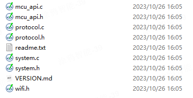
Step 2: Review macro definitions in protocol.h
Confirm product information
-
Define the product ID (PID).
PRODUCT_KEYis the macro defined for the PID. A PID is a unique identifier for each product. It can be found on the page of Product Development.#define PRODUCT_KEY "ax23rawjo4np****"If the
PRODUCT_KEYand the PID are inconsistent, you can go to Hardware Development > Download Documents section and download the latest SDK. -
Define the version number.
MCU_VERdefines the software version, which defaults to1.0.0. If you enable OTA updates for the MCU firmware, you need to update the MCU version number each time an update is installed.#define MCU_VER "1.0.0" -
Define the Wi-Fi pairing mode.
CONFIG_MODEdefines the pairing mode, which can be the default mode, safe mode, or anti-misoperation mode. The anti-misoperation mode is recommended.The following describes the three modes.
-
Default mode: Alternate between AP mode and EZ mode. If the module has not been paired or has been removed, it will stay in pairing mode after power on.
#define CONFIG_MODE CONFIG_MODE_DEFAULT -
Safe mode: For the first-time use, the module does not enter the pairing mode until the MCU sends the reset command. In pairing mode, if the module is not paired within the specified period (three minutes by default), it will automatically exit the pairing mode.
#define CONFIG_MODE CONFIG_MODE_LOWPOWER -
Anti-misoperation mode: A paired module that is physically reset will resume its network connection if it is not paired within the specified period (three minutes by default). Similarly, if a device that is physically reset is shut down due to an outage, it will resume its network connection after power on. In this mode, if a user removes a device from the app, the network connection history of this device will be cleared.
#define CONFIG_MODE CONFIG_MODE_SPECIAL -
Define the hold-time of the pairing mode. If you select safe mode or anti-misoperation mode, you can enable the macro
CONFIG_MODE_DELAY_TIMEand set the hold-time of the pairing mode. The hold-time can be between 3 and 10 minutes. It defaults to 3 minutes.#define CONFIG_MODE_DELAY_TIME 10
-
-
Specify a pairing mode. You can set the coexistence of EZ mode and AP mode or only AP mode available through
CONFIG_MODE_CHOOSE.-
0: EZ mode and AP mode coexist. This way, it is not necessary to switch between modes.#define CONFIG_MODE_CHOOSE 0 -
1: Only AP mode is supported.#define CONFIG_MODE_CHOOSE 1
-
-
Set low power mode. You can enable low power mode through
LONG_CONN_LOWPOWER, which is disabled by default.//#define LONG_CONN_LOWPOWER 0 // Disable low power mode. //#define LONG_CONN_LOWPOWER 1 // Enable low power mode.
Define transmit and receive buffer
-
Serial receive buffer: The buffer size depends on how often the serial data handler is called. If the MCU can quickly process serial data, the buffer size can be reduced.
-
Serial transmit buffer: The buffer size must be greater than the maximum length of DP data.
-
Buffer for serial data processing: The buffer size must be greater than the maximum length of DP data. If OTA updates and specific weather services are enabled, the buffer size must be greater than the maximum amount of payload.
/******************************************************************************
                        3: Define the transmit and receive buffer:
                    If your MCU has insufficient RAM, you can change the buffer size to 24 bytes.
******************************************************************************/
#ifndef SUPPORT_MCU_FIRM_UPDATE
#define WIFI_UART_RECV_BUF_LMT          16              //The serial receive buffer size, which can be reduced if your MCU has insufficient RAM.
#define WIFI_DATA_PROCESS_LMT           24              //The buffer size for serial data processing. It depends on the amount of DP data but must be greater than 24 bytes.
#else
#define WIFI_UART_RECV_BUF_LMT          128             //The serial receive buffer size, which can be reduced if your MCU has insufficient RAM.

//Set the proper buffer size. Consider the defined update package and specific weather services, if applicable.
#define WIFI_DATA_PROCESS_LMT           300             //The buffer size for serial data processing. When OTA updates are enabled, if you set the size of a single update package to 256 bytes, the buffer size must be greater than 260 bytes. If weather services are also enabled, more buffer is required.
//#define WIFI_DATA_PROCESS_LMT           600             //The buffer size for serial data processing. When OTA updates are enabled, if you set the size of a single update package to 512 bytes, the buffer size must be greater than 520 bytes. If weather services are also enabled, more buffer is required.
//#define WIFI_DATA_PROCESS_LMT           1200            //The buffer size for serial data processing. When OTA updates are enabled, if you set the size of a single update package to 1024 bytes, the buffer size must be greater than 1030 bytes. If weather services are also enabled, more buffer is required.

#endif

#define WIFIR_UART_SEND_BUF_LMT         48              //It depends on the amount of DP data but must be greater than 48 bytes.
Define working mode
-
If the reset button and LED indicator for network status are connected to the MCU, the module works with the MCU to process network events, which is most commonly used. You need to comment out the macro
WIFI_CONTROL_SELF_MODE.//#define WIFI_CONTROL_SELF_MODE //The module processes the reset button and LED indicator itself. If you use an external reset button or LED indicator, disable this macro. -
If the reset button and LED indicator for network status are connected to the Wi-Fi module, the module processes network events itself. You need to enable the macro
WIFI_CONTROL_SELF_MODE. Specify the GPIO pins connected to the indicator and the button in the following two macros.#ifdef WIFI_CONTROL_SELF_MODE //The module processes network events itself. #define WF_STATE_KEY 14 //The indicator for network status. Set it according to your circuit. #define WF_RESERT_KEY 0 //The button for Wi-Fi module reset. Set it according to your circuit. #endif
Step 3: Port protocol.c file and functions
-
Copy the
wifi.hfile to the folder where Wi-Fi files are stored, such as themain.cfolder. -
Call the
wifi_protocol_init()function in themcu_api.cfile after the MCU serial port and other peripherals are initialized. -
Specify the serial transmission function with
uart_transmit_output()in theprotocol.cfile, and delete#error.Example:
/** * @brief Send serial data * @param[in] {value} The one byte of data to be sent by UART. * @return Null */ void uart_transmit_output(unsigned char value) { //#error "Specify the UART transmission function and delete this line" UART3_SendByte(value); /* //Example: extern void Uart_PutChar(unsigned char value); Uart_PutChar(value); //Serial port transmitting function */ } -
In the interrupt handler for serial data reception, call
uart_receive_input()in themcu_api.cfile and pass in the received data as the parameters.Example:
void USART3_IRQHandler(void) { unsigned char Res=0; if((USART3->SR&UART_FLAG_RXNE) != 0) { Res=USART3->DR; uart_receive_input(Res); } } -
After the MCU runs in the
while(1)loop, it calls thewifi_uart_service()function in themcu_api.cfile. The sample code inmain.cis as follows:#include "wifi.h" ... void main(void) { wifi_protocol_init(); ... while(1) { wifi_uart_service(); ... } ... }- The MCU must directly call
wifi_uart_service()in themcu_api.cfile in thewhile(1)loop. - After the program is initialized, if an interrupt service routine (ISR) is necessary, you must keep it as short as possible and not call the data reporting function to avoid loss of data.
- The MCU must directly call
Step 4: Call DP data reporting and sending functions
A data point (DP) can be defined with one of the following six data types.
| Type | Description |
|---|---|
| Boolean | Used for DPs of switch products, such as the switch, ECO, and screen. |
| Enum | Used for DPs that have multiple kinds of status, such as working mode, fan speed, and swing direction. |
| Value | Used for DPs that have integer values, such as temperature and battery level. |
| Fault | Used for reporting device faults, denoted in bitmap format. |
| String | Used for DPs of string type. Used for DPs that transmit data in string format. You can choose this string type if other data types are not applicable. |
| Raw | Used for DPs that have no requirements for data format, transmitting raw data either in plaintext or encrypted text. The data format, packet, and data parsing must be unified between the sender and the receiver. |
Scenario 1: Report all DPs
After the module is restarted or paired again, it will initiate a status query. The MCU must return the status of all DPs.
-
Open
protocol.cand find the functionall_data_update(void). -
Specify the initial values in corresponding functions for all DPs to be reported. These values will be displayed on the mobile app.
Avoid manually calling
all_data_update()because this function will be automatically triggered at the specified time./** * @brief Upload the status of all DPs for synchronization with the app. * @param Null * @return Null * @note The MCU implements the data reporting in this function, which must support two data transfer types, namely send only as well as send and report. */ void all_data_update(void) { //#error "Complete the example of two data transfer types and delete this line" /* //This code is automatically generated. You need to edit it based on the actual DPs. mcu_dp_bool_update(DPID_SWITCH,current on/off status); //Report Boolean data mcu_dp_value_update(DPID_TEMP_SET,current temperature setting); //Report value data mcu_dp_value_update(DPID_TEMP_CURRENT,current temperature); //Report value data mcu_dp_enum_update(DPID_MODE,current mode); //Report enum data mcu_dp_enum_update(DPID_FAN_SPEED_ENUM,current speed); //Report enum data mcu_dp_enum_update(DPID_STATUS,current status); //Report enum data mcu_dp_bool_update(DPID_ECO,current ECO mode); //Report Boolean data mcu_dp_bool_update(DPID_DRYING,current drying mode); //Report Boolean data mcu_dp_bool_update(DPID_VENTILATION,current ventilation mode); //Report Boolean data mcu_dp_bool_update(DPID_HEAT,current auxiliary heat); //Report Boolean data mcu_dp_bool_update(DPID_LIGHT,current light); //Report Boolean data mcu_dp_bool_update(DPID_CHILD_LOCK,current child lock); //Report Boolean data mcu_dp_bool_update(DPID_BEEP,current beep); //Report Boolean data mcu_dp_value_update(DPID_HUMIDITY_SET,current humidity setting); //Report value data mcu_dp_value_update(DPID_HUMIDITY_CURRENT,current humidity); //Report value data mcu_dp_enum_update(DPID_TEMP_UNIT_CONVERT,current temperature unit); //Report enum data mcu_dp_enum_update(DPID_COUNTDOWN_SET,current countdown); //Report enum data mcu_dp_value_update(DPID_COUNTDOWN_LEFT,countdown time left); //Report value data mcu_dp_fault_update(DPID_FAULT,current fault alert); //Report fault data mcu_dp_value_update(DPID_TEMP_CURRENT_F,current temperature in °F); //Report value data mcu_dp_value_update(DPID_TEMP_SET_F,current temperature setting in °F); //Report value data mcu_dp_bool_update(DPID_SLEEP,current sleep feature); //Report Boolean data mcu_dp_bool_update(DPID_CLEANING,current self-cleaning); //Report Boolean data mcu_dp_bool_update(DPID_SWITCH_VERTICAL,current vertical swing); //Report Boolean data mcu_dp_enum_update(DPID_GEAR_VERTICAL,current vertical swing level); //Report enum data mcu_dp_value_update(DPID_ANGLE_VERTICAL,current vertical swing angle); //Report value data mcu_dp_bool_update(DPID_SWITCH_HORIZONTAL,current horizontal swing); //Report Boolean data mcu_dp_enum_update(DPID_GEAR_HORIZONTAL,current horizontal swing level); //Report enum data mcu_dp_value_update(DPID_ANGLE_HORIZONTAL,current horizontal swing angle); //Report value data mcu_dp_bool_update(DPID_DISPLAY,current screen display switch); //Report Boolean data */ }
Scenario 2: Report a single DP
When the status of a single DP changes, the MCU must proactively report the current DP status to sync with the app. The data format is mcu_dp_xxxx_updata(DPID_X,n), where DPID_X is the DP whose status changes. You can call the functions in all_data_update() individually.
Example:
mcu_dp_bool_update(DPID_SWITCH,1); //Report Boolean data
mcu_dp_value_update(DPID_TEMPER_SET,25); //Report value data
mcu_dp_string_update(DPID_DAY,"1234",4); //Report string data
Scenario 3: Process received DP data
In protocol.c, each DP that can send control commands has an individual command handler. The format is dp_download_xxx_handle(), where xxx is the DP that can send commands. After the function parses the DP, the MCU will execute commands accordingly. Take the received switch DP data as an example:
/*****************************************************************************
Function name: dp_download_switch_handle
Description: DPID_SWITCH handler
Input parameters: value indicates the data source
        length: the length of the data
Return parameters: Returns SUCCESS on success, and ERROR on failure.
Note: For the type of send and report, the module must return the result to the cloud for synchronization with the app.
*****************************************************************************/
static unsigned char dp_download_switch_handle(const unsigned char value[], unsigned short length)
{
    //For example, a DP of Boolean type
    unsigned char ret;
    //0: indicates off. 1: indicates on.
    unsigned char switch1;

    switch1 = mcu_get_dp_download_bool(value,length);
    if(switch1 == 0)
    {
        //The switch is off.
        MCU_OFF_switch1();
    }
    else
    {
        //The switch is on.
        MCU_ON_switch1();
    }

    //The result of DP data processing.
    ret = mcu_dp_bool_update(DPID_SWITCH,switch1);
    if(ret == SUCCESS)
        return SUCCESS;
    else
        return ERROR;
}
If the change of device status is not triggered by control commands, the MCU will call mcu_dp_bool_update(DPID_SWITCH_1,switch_1); to upload the current status of the DP for feedback. You can specify the reporting timing as needed.
Step 5: Add device pairing and LED indicator functions
The device pairing and LED indicator functions are required only when the module works with the MCU to process network events.
After porting the protocol, add the pairing command and LED indicator functions. Write the pairing trigger and network status indicator based on the pairing mode and working mode, respectively. You can customize how devices are paired and display pairing status, such as using common methods like button presses and LED blinking.
Two pairing modes are available.
-
EZ mode: an easy-to-use pairing mode, indicated by quick blinking.
-
AP mode: reliable pairing, indicated by slow blinking.
- We recommend that you implement both modes to handle different scenarios.
- Wi-Fi and Bluetooth combo modules also support pairing over Bluetooth in addition to the two modes mentioned.
Pairing command
You can implement the pairing command through mcu_reset_wifi() or mcu_set_wifi_mode(). The function is called in the button handler after the reset button is pressed.
-
mcu_reset_wifi()resets the Wi-Fi module, with all the pairing information cleared. Each timemcu_reset_wifi()is called, the pairing mode is toggled from AP mode to EZ mode or EZ mode to AP mode.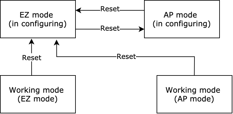
-
mcu_set_wifi_mode()takes two parameters:SMART_CONFIGandAP_CONFIG. After the function is called, all pairing information will be cleared and the module enters EZ mode or AP mode.
Pairing indication
To get the Wi-Fi module’s network status, call mcu_get_wifi_work_state() during while(1) loop. Write the blinking mode of the LED indicator according to the network status.
| Network status | Description | Status value | LED indicator |
|---|---|---|---|
| Status 1 | Pairing in EZ mode. | 0x00 | The LED blinks quickly at an interval of 250 milliseconds. |
| Status 2 | Pairing in AP mode. | 0x01 | The LED blinks slowly at an interval of 1,500 milliseconds. |
| Status 3 | The Wi-Fi network is set up, but the device is not connected to the router. | 0x02 | The LED is off. |
| Status 4 | The Wi-Fi network is set up, and the device is connected to the router. The device can be controlled over a local area network (LAN). | 0x03 | The LED indicator is steady on. |
| Status 5 | The device is connected to the router and the cloud. The device can be controlled over a local area network (LAN) or from the cloud. | 0x04 | The LED indicator is steady on. |
| Status 6 | The Wi-Fi device is in low power mode. | 0x05 | The LED is off. |
| Status 7 | EZ mode and AP mode coexist. | 0x06 | The LED blinks quickly at an interval of 250 milliseconds. |
Call mcu_get_wifi_work_state() to get the Wi-Fi connection status.
void main(void)
{
    ...
    while(1)
    {
        ...
        switch(mcu_get_wifi_work_state())
        {
            case SMART_CONFIG_STATE:
                //In EZ mode, the LED flickers quickly.
            break;
            case AP_STATE:
                //In AP mode, the LED flickers slowly.
            break;
            case WIFI_NOT_CONNECTED:
                //The Wi-Fi network has been set up and is connecting to the router. The LED is off.
            break;
            case WIFI_CONNECTED:
                //The Wi-Fi network is connected to the router. The LED is steady on.
            break;
            default:break;
        }
        ...
    }
}
(Optional) Step 6: Enable production testing
The production testing feature for the Wi-Fi module is enabled by default. To help you smoothly and efficiently carry out mass production, it is recommended to enable the production testing feature.
#define WIFI_TEST_ENABLE //Enable the production test feature.
For more information, see Production Testing and Production Testing Modes.
(Optional) Step 7: Enable MCU OTA update
The MCU SDK allows you to update the MCU firmware via OTA. The Wi-Fi module downloads the update from the cloud and sends it to the MCU through the serial port. After installing the update, the MCU will run the latest firmware. To support the MCU OTA update feature, enable SUPPORT_MCU_FIRM_UPDATE, which is disabled by default.
#define SUPPORT_MCU_FIRM_UPDATE
For more information, see MCU OTA Update.
(Optional) Step 8: Enable extended features
You can enable the extended features as needed to unlock more potential uses for your product. For more information, see Extended Features.
Is this page helpful?
YesFeedbackIs this page helpful?
YesFeedback


