Production Test
This topic describes four production test modes during production tests of Tuya Wi-Fi general modules. MCU developers select one or more production test commands as needed. They determine whether the production test succeeded based on the data returned by the Wi-Fi module.
This document will no longer be updated. If you want to learn more about MCU standard protocol, see MCU Standard Protocol. For production testing, refer to Production Testing.
Overview
During production, production test commands are used to test Wi-Fi module functions, and communication capability between modules and control panels.
-
Scan the designated router
In this mode, after receiving
0x0ecommand from the MCU, the module scans the designated wireless signal and returns the signal strength value. According to the signal strength, the MCU determines whether the radio frequency (RF) performance of the Wi-Fi module is qualified. In this mode, the production test router is not connected to the internet. This mode features short duration and high production test efficiency. Multiple devices can be tested at the same time. -
Connect the designated router
In this mode, through
0x2Ccommand word, the MCU sends the SSID and password of the production test router to the module. The module is connected to the router, and returns cloud communication status. Thus, the MCU determines whether the production test succeeded according to the returned network status. In this mode, the production test router shall be connected to the internet. Due to the limited carrying capacity of the router, not too many devices can be tested at the same time. Since a cloud connection test is carried out, the production test result is more reliable. -
IR functional test
This mode is a separate infrared (IR) functional test. It tests whether IR receiving and transmitting pins work properly. Omit this mode if the relevant function is not used.
-
Bluetooth functional test This mode is a separate Bluetooth functional test, which detects the Bluetooth scanning results and signal strength percentage. Omit this mode if the relevant function is not used.
Scan the designated router
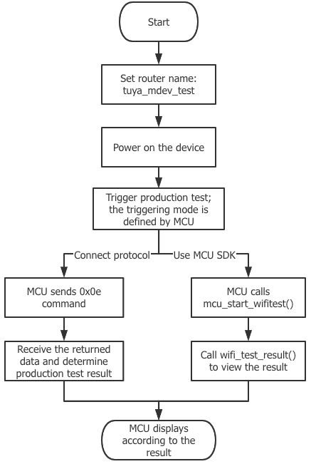
The method to trigger the production test can be defined by the MCU. After the module and the MCU have completed initialization data transmission, the MCU sends 0x0e command, and the module scans the designated router SSID of tuya_mdev_test. The scanning result and signal strength percentage are returned, so the MCU determines whether the production test succeeded or failed according to signal strength.
Things to note
- The router is not connected to the internet, but it shall generate a Wi-Fi signal, whose name is
tuya_mdev_test. It is recommended that the distance between the router and the device should be about five meters. - Generally, the signal strength greater than or equal to 60% is qualified. It can be adjusted according to the production line and workshop environment.
- After the module has completed initialization transmission (the MCU replies to the heartbeat packet and product query packet of the module), the MCU sends a production test command to the module. It is recommended that the production test should be triggered five seconds after power-on.
Flow chart of production test

-
Prepare one 2.4 GHz wireless router that is connected to the internet, and set the router SSID as
tuya_mdev_test. -
Trigger the production test and power on the device under test. The production test can be triggered after the module has completed the power-on initialization transmission. Triggering methods can be defined by developers. It is recommended to trigger the production test with rarely used combination buttons.
-
According to the connection condition, the developer can send a production test command to the module. The following two connections are supported.
-
MCU_SDKis used After triggering of the production test is detected, you can call themcu_start_wifitest()function to enable the production test. -
MCU_SDKis not used See commands in the Wi-Fi functional test (scan the designated router) of the Wi-Fi general serial port protocol, and send the0x0ecommand to the module.
For example,
0x55 aa 03 0e 00 00checksumField Length (byte) Description Header 2 0x55aa Version 1 0x03 Command 1 0x0e Data length 2 0x0000 Data Data None Checksum 1 Start from the header, add up all the bytes, and then divide the sum by 256 to get the remainder -
-
Receive the returned data, and view the test result.
According to the connection condition (whether Tuya
MCU_SDKis used), you can view the test result.-
MCU_SDKis usedView the test result in the
wifi_test_resultfunction of theprotocol.cfile.
void wifi_test_result(unsigned char result,unsigned char rssi) { #error "Provide success/failure code of the Wi-Fi functional test, and delete this row on completion" if(result == 0) { //Test failed if(rssi == 0x00) { //The `tuya_mdev_test` router is not found } else if(rssi == 0x01) { //The module is not authorized } } else { //Test succeeded //RSSI is signal strength (0–100, 0 for the weakest signal, and 100 for the strongest signal } }-
MCU_SDKis not usedIf you connect a serial port protocol, you can see commands in the Wi-Fi functional test (scan the designated router) of the Wi-Fi general serial port protocol, and view the test result according to the received data.
Note: The module returns
0x55 aa 00 0e 00 02 01 64checksum. The signal strength is 100, meaning the production test succeeded.
The MCU sends the following command:
Field Length (byte) Description Header 2 0x55aa Version 1 0x03 Command 1 0x0e Data length 2 0x0000 Data Data None Checksum 1 Start from the header, add up all the bytes, and then divide the sum by 256 to get the remainder The module returns the following command:
Field Length (byte) Description Header 2 0x55aa Version 1 0x00 Command 1 0x0e Data length 2 0x0002 Data 2 - Data[0]:
- 0x01: success. Data[1] indicates signal strength (from 0 to 100, 0 for the weakest, 100 for the strongest).
- 0x00: failure. If Data[1] is 0x00, the specified SSID is not found.
- Data[1]: 0x01. The authorization key is not programmed to the module.
Checksum 1 Start from the header, add up all the bytes, and then divide the sum by 256 to get the remainder -
-
Show the test result. Based on the acquired data, the result can be prompted through voice, display, LED lights, and more.
Connect the designated router
The method to trigger the production test can be defined by the MCU. After the module has completed power-on initialization transmission, through the 0x2C command, the MCU sends the SSID and password of the production test router to the module. After receiving pairing information, the Wi-Fi module connects the router to access the cloud, and returns the changes of network status. According to network status changes of the 0x03 command, the MCU determines whether the production test succeeded.
Things to note
- The MCU sends router information to the module, and the module returns data successfully. Then, the module uses relevant information to connect the router.
- The MCU checks whether the router is connected according to the
0x03command (status 3: Wi-Fi has been configured and the router is connected). - It is considered a failure in case that:
- The MCU receives a returned failure status.
- The MCU fails to receive a status packet of successful connection to the router for more than 15 seconds.
- After the production test succeeded, the test command can be resent, in order to enter the production test again. If the status packet of connecting the router is not received, it means that the module is being tested. After the module is reset or powered on again, the test command shall be sent, in order to enter the production test again.
- The module can complete the connection test when the module is not paired.
- Before the production test, the MCU shall reply to the heartbeat packet and product query packet from the module. After the module has completed initialization transmission, it enters the production test mode of connecting the router.
- The router name string supports a maximum of 32 bytes, and the router password string supports a maximum of 64 bytes.
Flow chart of production test
-
Prepare one 2.4 GHz wireless router that is connected to the internet, and make sure that network communication works properly.
-
Power on the device under test, and trigger the production test after the module has completed power-on initialization transmission. Triggering methods can be defined by you. It is recommended to trigger the production test with rarely used combination buttons.
-
According to the connection condition, the developer can send a production test command to the module. The following two connections are supported.
-
MCU_SDKis usedAfter triggering of the production test is detected, you can call the
mcu_start_connect_wifitest()function to enable the production test. Fill in the SSID and password of the router. -
MCU_SDKis not used (integrate with the serial port protocol)See commands in the Wi-Fi functional test (connected to the designated router) of the Wi-Fi general serial port protocol, and send the
0x2Ccommand to the module.
The MCU sends the following command:
Field Length (byte) Description Header 2 0x55aa Version 1 0x03 Command 1 0x2C Data length 2 xxxx Data Data {"ssid":”xxx”,”password”:”xxxxxxxx”}
ssid: router name
password: router passwordChecksum 1 Start from the header, add up all the bytes, and then divide the sum by 256 to get the remainder Note: Data is transmitted in the hexadecimal format of ASCII codes.
-
-
Receive the returned data, and view the test result. According to the connection condition (whether Tuya
MCU_SDKis used), you can view the test result.-
MCU_SDKis usedView the test result in the
wifi_connect_test_resultfunction of theprotocol.cfile.
void wifi_connect_test_result(unsigned char result) { //#error "Provide success/failure code of the Wi-Fi functional test, and delete this row on completion" if(result == 0) { // Failed to receive router information. Check whether the router information packet is an intact JSON data packet } else { // Router information is received successfully. In the production test result, pay attention to the Wi-Fi working status of the `WIFI_STATE_CMD` command } }-
MCU_SDKis not usedAfter the command of connecting the designated router is sent by the MCU and received by the Wi-Fi module, the Wi-Fi module returns the receipt result. The successful result means that serial port data transmission is successful. For the network connection test, pay attention to the data changes of the
0x03command that is sent by the module during a network connection.
The module returns the following command:
Field Length (byte) Description Header 2 0x55aa Version 1 0x00 Command 1 0x2c Data length 2 0x0001 Data 1 - 0x00: Failed to receive the router information. Check whether the router information packet sent is an intact JSON data packet.
- 0x01: The router information is successfully received. Pay attention to the network status packet in the returned result.
Checksum 1 Start from the header, add up all the bytes, and then divide the sum by 256 to get the remainder For the router connection result, see the command of Reporting device network status in the protocol.
- When the MCU receives a network status frame of status 4 (Wi-Fi has been configured and connected to the router) from the module, the module is connected to the designated router successfully.
- If the MCU receives a receipt failure prompt from the module, or fails to receive the status packet of connecting the router for a long time (more than 15 seconds), the production test is considered a failure.
Field Length (byte) Description Header 2 0x55aa Version 1 0x00 Command 1 0x03 Data length 2 0x0001 Data 1 Indicates Wi-Fi working status.
0x00: status 1
0x01: status 2
0x02: status 3
0x03: status 4
0x04: status 5
0x05: status 6Checksum 1 Start from the header, add up all the bytes, and then divide the sum by 256 to get the remainder -
-
Show the test result. Based on the acquired data, the result can be prompted through voice, display, LED lights, and more.
IR functional test
IR receiving and transmitting tests are performed on modules that support IR functions.
Things to note
- There is not much IR signal in the test environment, and the IR signal does not interleave.
- Production test can be started five seconds after the system is powered on and the module is started.
- IR production test function is available when the device is not paired.
- After entering the IR production test status, the module enters the IR learning status.
- Once the module enters IR production test mode, the module remains in the production test status, learns continuously, and sends the learned data. The module exits the production test after the pairing succeeds, or the module is powered off.
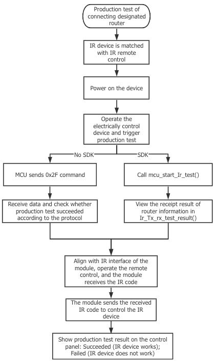
Flow chart of production test
-
Prepare one IR device and IR remote control.
-
Power on the device under test, and trigger the production test after the module has completed power-on initialization transmission. Triggering methods can be defined by you. It is recommended to trigger the production test with rarely used combination buttons.
-
According to the connection condition, the developer can send a production test command to the module. The following two connections are supported.
-
MCU_SDKis usedAfter triggering of the production test is detected, you can call the
mcu_start_ir_test()function to enable the production test. -
MCU_SDKis not usedSee the commands in Production test of IR receiving and sending of the general serial port protocol of Wi-Fi modules, and send corresponding data to the module.
Note: For example, the module returns
0x55 aa 03 2f 00 00checksum.
The MCU sends the following command:
Field Length (byte) Description Header 2 0x55aa Version 1 0x03 Command 1 0x2f Data length 2 0x0000 Data Data None Checksum 1 Start from the header, add up all the bytes, and then divide the sum by 256 to get the remainder -
-
According to the connection condition, the developer can send a production test command to the module. The following two connections are supported.
-
MCU_SDKis usedView the test result in the
ir_tx_rx_test_resultfunction of theprotocol.cfile.
void ir_tx_rx_test_result(unsigned char result,unsigned char rssi) { //#error "Implement the success/failure code of the infrared receiving and transmitting production test. Delete this line after completion" if(result == 0) { //Enter the IR receiving and transmitting production test successfully } else { // Failed to enter the IR receiving and transmitting production test. Check the data packet sent } }-
MCU_SDKis not usedYou can determine whether the IR production test succeeded or failed according to the received
0x2fcommand. If the infrared test device does not return the status for more than 15 seconds, it is determined that the production test has failed.- 0: Enter the IR receiving and transmitting production test successfully. The IR remote control shall be aligned with the IR receiving port of the module. After learning, an IR code can be sent to control the device. If the device shows the same status as the remote control, the IR receiving and transmitting production test succeeded.
- 1: Failed to enter the IR receiving and transmitting production test.
The module returns the following command:
Field Length (byte) Description Header 2 0x55aa Version 1 0x00 Command 1 0x2f Data length 2 0x0001 Data Data 0x00: Entered the IR receiving and transmitting production test successfully
0x01: Failed to enter the IR receiving and transmitting production testChecksum 1 Start from the header, add up all the bytes, and then divide the sum by 256 to get the remainder -
-
If the IR device under control reacts correctly, the production test succeeded. If the IR device under control does not react correctly, the production test failed.
Bluetooth functional test
For more information about Bluetooth functional test mode, see Bluetooth functional test.
Is this page helpful?
YesFeedbackIs this page helpful?
YesFeedback


