Production Testing
This topic describes the production testing features that allow you to verify Wi-Fi and Bluetooth functionalities, as well as network signal strength. For more information, see Production Testing Modes.
Scenario
After you have tested the basic features, you can perform functionality testing separately or integrate it into the end product test to verify the wireless performance. You can define how a test is triggered as needed.
Commands
The commands used in the functionality test.
| Command | Description |
|---|---|
| 0x0e | Test Wi-Fi functionality (scanning) |
| 0x2c | Test Wi-Fi functionality (connection) |
| 0x24 | Get Wi-Fi signal strength |
| 0x35 (subcommand: 0x01) | Test Bluetooth functionality (scanning) |
Test Wi-Fi scanning (0x0e)
This command is used to test the radio frequency performance of Wi-Fi modules in mass production.
How to use this command: You can call this command at least five seconds after the module is powered on because the initialization takes a while. After the module receives the command 0x0e, it will scan for the Wi-Fi network named tuya_mdev_test and return the result. If the specified network is discovered, the result is the signal strength in percentage, ranging from 0 to 100 with a step of 20. The MCU determines whether the Wi-Fi RF performance is acceptable based on the signal strength.
Signal strength
| Signal strength | Receive power (dBm) |
|---|---|
| 0 | ≤ -100 |
| 40 | > -100, ≤ -80 |
| 60 | > -80, ≤ -60 |
| 80 | > -60, ≤ -40 |
| 100 | > -40 |
-
The test command must be sent after the module initialization is completed. Otherwise, the command might not work. For more information, see Module initialization.
-
Set up the router: Prepare a 2.4 GHz wireless router and set the router’s SSID to
tuya_mdev_test. Internet connection and password setup are not required. -
Testing condition: It is recommended that the distance between the router and the device under test should be about five meters. If the signal strength is greater than or equal to 60%, the device is acceptable. The specific testing conditions depend on your production line and environment. You can test multiple devices simultaneously.
The MCU sends the following data.
| Field | Bytes | Description |
|---|---|---|
| Header | 2 | 0x55aa |
| Version | 1 | 0x03 |
| Command | 1 | 0x0e |
| Data length | 2 | 0x0000 |
| Data | 0 | None |
| Checksum | 1 | Start from the header, add up all the bytes, and then divide the sum by 256 to get the remainder. |
Example: 55 aa 03 0e 00 00 10
The module returns the following data.
| Field | Bytes | Description |
|---|---|---|
| Header | 2 | 0x55aa |
| Version | 1 | 0x00 |
| Command | 1 | 0x0e |
| Data length | 2 | 0x0002 |
| Data | 2 | The data length is two bytes. Data[0]: 0x00 for failure, and 0x01 for success.
|
| Checksum | 1 | Start from the header, add up all the bytes, and then divide the sum by 256 to get the remainder. |
Example:
- When the module finds the target network, with a signal strength of 40, it returns
55 aa 00 0e 00 02 01 28 38. - When the module does not find the specified SSID, it returns
55 aa 00 0e 00 02 00 00 0f.
Test Wi-Fi connection (0x2C)
This test requires an internet connection. The number of devices you can test simultaneously depends on the network capacity. Note that since the mobile app does not send the pairing token in the test process, the device is not actually activated, but the cloud connectivity is verified.
How to use this command: Call this command at least five seconds after the module is powered on because the initialization takes a while. The target module must be unpaired. The MCU sends the SSID and password of the specified router to the module through 0x2c. The module connects to the router and returns the status of cloud connectivity so that the MCU can determine the test result based on what the module returns.
- Before the test, make sure that the MCU has responded to the heartbeat and product information query from the module and the initialization is completed.
- The MCU can determine if the module is connected to the router based on network status 4.
- The MCU can determine the failure to connect to the specified Wi-Fi network with the following:
- The MCU receives a failure result.
- The MCU does not receive the packet of network status 4 within 15 seconds.
- After a successful test, you can send the test command again to repeat the test. However, if the MCU does not receive network status 4, the module is in the test progress. In this case, reset or restart the module and then send the test command again.
- Make sure that the module has not paired. Otherwise, the test will fail.
- The maximum length of the SSID and password is 32 bytes and 64 bytes respectively.
The MCU sends the following data.
| Field | Bytes | Description |
|---|---|---|
| Header | 2 | 0x55aa |
| Version | 1 | 0x03 |
| Command | 1 | 0x2C |
| Data length | 2 | n |
| Data | n |
{"ssid":"xxx", "password":"xxxxxxxx"}
|
| Checksum | 1 | Start from the header, add up all the bytes, and then divide the sum by 256 to get the remainder. |
Example: {"ssid":"xxx", "password":"12345678"}
55 aa 03 2c 00 24 7b 22 73 73 69 64 22 3a 22 78 78 78 22 2c 22 70 61 73 73 77 6f 72 64 22 3a 22 31 32 33 34 35 36 37 38 22 7d 2c
The module returns the following data.
| Field | Bytes | Description |
|---|---|---|
| Header | 2 | 0x55aa |
| Version | 1 | 0x00 |
| Command | 1 | 0x2C |
| Data length | 2 | 0x0001 |
| Data | 1 | The data length is one byte. Data[0]:
|
| Checksum | 1 | Start from the header, add up all the bytes, and then divide the sum by 256 to get the remainder. |
Example: 55 aa 00 2c 00 01 01 2d, indicating success.
Get Wi-Fi signal strength (0x24)
When the module is connected to the Wi-Fi network, the MCU can send this command to get the current signal strength to determine the network quality.
The MCU sends the following data.
| Field | Bytes | Description |
|---|---|---|
| Header | 2 | 0x55aa |
| Version | 1 | 0x03 |
| Command | 1 | 0x24 |
| Data length | 2 | 0 |
| Data | N | None |
| Checksum | 1 | Start from the header, add up all the bytes, and then divide the sum by 256 to get the remainder. |
Example: 55 aa 03 24 00 00 26
The module returns the following data.
| Field | Bytes | Description |
|---|---|---|
| Header | 2 | 0x55aa |
| Version | 1 | 0x00 |
| Command | 1 | 0x24 |
| Data length | 2 | 0x0001 |
| Data | Data |
|
| Checksum | 1 | Start from the header, add up all the bytes, and then divide the sum by 256 to get the remainder. |
Example: 55 aa 00 24 00 01 D5 F9, indicating the received signal strength indicator (RSSI) is -43 dB.
The signal strength value is in hexadecimal format (padding). If the RSSI is less than -70 dB, the possibility that a device goes offline is high. Check the network environment and antenna performance.
Test Bluetooth scanning (0x35 & 0x01)
The module scans for the specified Bluetooth beacon ty_mdev and returns the result and signal strength in percentage. For more information about the signal strength description, see Test Wi-Fi functionality (scanning).
How to use this command: Prepare a Bluetooth beacon and set its identifier to ty_mdev. It is recommended that the distance between the router and the device under test should be about five meters. If the signal strength is greater than or equal to 60%, the device is acceptable. The specific testing conditions depend on your production line and environment.
To scan Bluetooth beacons, testing needs to be performed while the module is in pairing mode. If the module is not in pairing mode, you need to send a reset command to make the module enter pairing mode.
The MCU sends the following data.
| Field | Length | Description |
|---|---|---|
| Header | 2 | 0x55aa |
| Version | 1 | 0x03 |
| Command | 1 | 0x35 |
| Data length | 2 | 0x0001 |
| Data | 1 | 0x01 (subcommand) |
| Checksum | 1 | Start from the header, add up all the bytes, and then divide the sum by 256 to get the remainder. |
Example: 55 aa 03 35 00 01 01 39
The module returns the following data.
| Field | Bytes | Description |
|---|---|---|
| Header | 2 | 0x55aa |
| Version | 1 | 0x00 |
| Command | 1 | 0x35 |
| Data length | 2 | 0x0003 |
| Data | 1 | 0x01 (subcommand) |
| 2 | The data length is two bytes. Data[0]: 0x00 for failure, and 0x01 for success.
|
|
| Checksum | 1 | Start from the header, add up all the bytes, and then divide the sum by 256 to get the remainder. |
Example: 55 aa 00 35 00 03 01 01 14 4d
Example
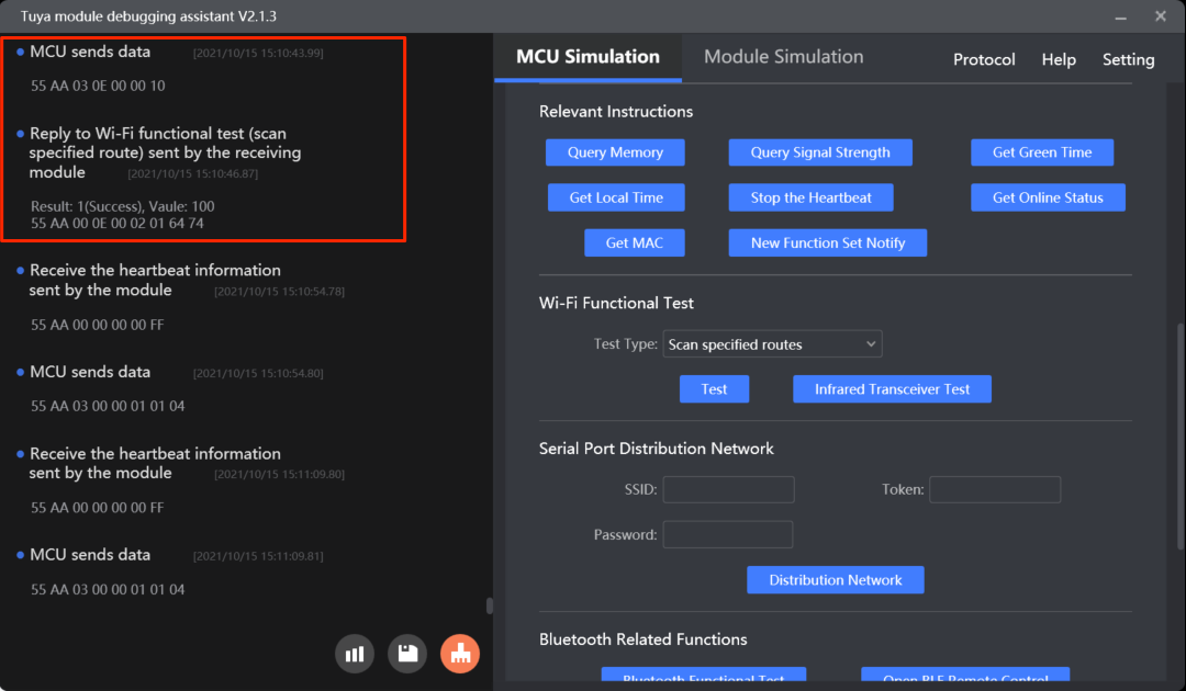
Scan for the specified router
wifi_test_result() from protocol.c is used for the MCU to get the test result.
The process is as follows:
-
Enable
WIFI_TEST_ENABLEto turn on the Wi-Fi functionality test.#define WIFI_TEST_ENABLE // Enable Wi-Fi functionality testing (scan for the specified network). -
The MCU gets the test result from
data_handle()and callswifi_test_result()to process the result.void data_handle(unsigned short offset) { ...... #ifdef WIFI_TEST_ENABLE case WIFI_TEST_CMD: // Scan for the specified network. result = wifi_data_process_buf[offset + DATA_START]; rssi = wifi_data_process_buf[offset + DATA_START + 1]; wifi_test_result(result, rssi); break; #endif ...... } -
You need to implement the function
wifi_test_resultinprotocol.c./** * @brief Get the Wi-Fi functionality test result. * @param[in] {result} The test result. * @ref 0: Failed * @ref 1: Succeeded * @param[in] {rssi} If the test is successful, the signal strength will be returned. Otherwise, error codes will be returned. * @return Null * @note To be implemented by you. */ void wifi_test_result(unsigned char result,unsigned char rssi) { #error "Complete the code for test results and then delete this row" if(result == 0) { //Test failed. if(rssi == 0x00) { //The network with an SSID of `tuya_mdev_test` is not found. }else if(rssi == 0x01) { //The module is not authorized. } }else { //Test succeeded. //RSSI indicates the signal strength, ranging from 0 to 100. 0 represents the weakest, and 100 represents the strongest. } } -
Module Debugging Assistant
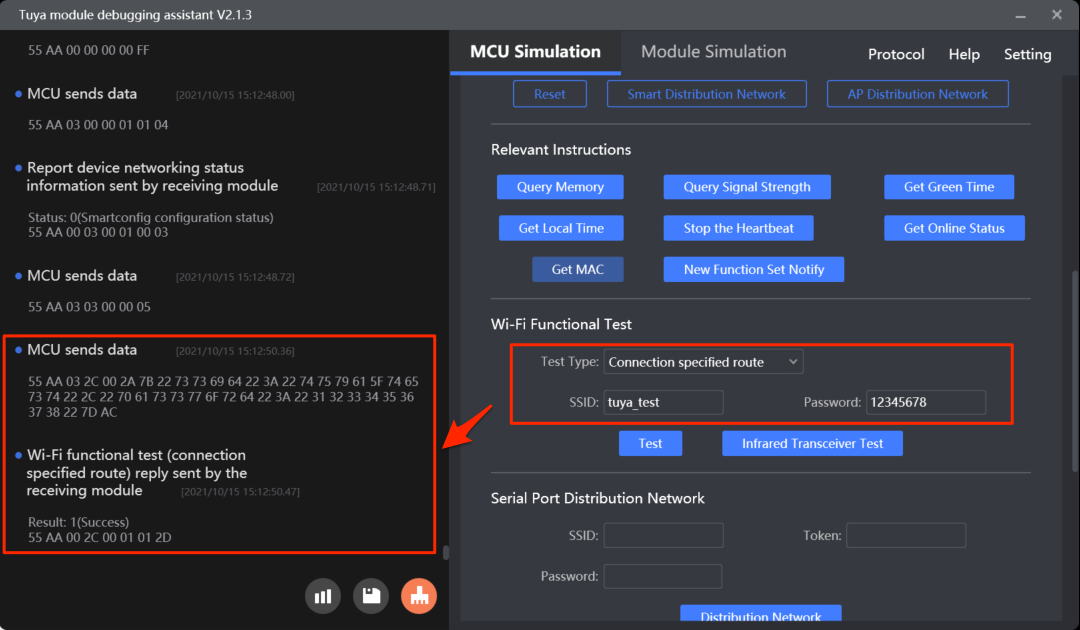
Connect to the specified router
mcu_start_connect_wifitest() in mcu_api.c is used for the MCU to send the SSID and password of the specified network to the module to initiate the connection test.
The process is as follows:
-
Enable
WIFI_CONNECT_TEST_ENABLEto turn on the functionality test on the Wi-Fi connection.#define WIFI_CONNECT_TEST_ENABLE // Enable functionality test on the Wi-Fi connection. -
The MCU calls
mcu_start_connect_wifitest()to report the SSID and password of the specified network to initiate a test.void data_handle(unsigned short offset) { ...... #ifdef WIFI_CONNECT_TEST_ENABLE case WIFI_CONNECT_TEST_CMD: // Connect to the specified Wi-Fi network. result = wifi_data_process_buf[offset + DATA_START]; wifi_connect_test_result(result); break; #endif ...... } -
The MCU gets the test result from
data_handle()and callswifi_connect_test_result()to process the result./** * @brief The MCU initiates a functionality test on the Wi-Fi connection. * @param[in] {ssid_buf} The address where the SSID string is saved. The length of an SSID can be up to 32 bytes. * @param[in] {passwd_buffer} The address where the password string is saved. The length of a password can be up to 64 bytes. * @return Null * @note To be implemented by you. */ void mcu_start_connect_wifitest(unsigned char *ssid_buf,unsigned char *passwd_buffer) { unsigned short send_len = 0; if( my_strlen(ssid_buf) > 32 | | my_strlen(passwd_buffer) > 64) { //printf("ssid_buf or passwd_buffer is too long!"); return; } send_len = set_wifi_uart_buffer(send_len, "{\"ssid\":\"", my_strlen("{\"ssid\":\"")); send_len = set_wifi_uart_buffer(send_len,ssid_buf,my_strlen(ssid_buf)); send_len = set_wifi_uart_buffer(send_len, "\",\"password\":\"", my_strlen("\",\"password\":\"")); send_len = set_wifi_uart_buffer(send_len,passwd_buffer,my_strlen(passwd_buffer)); send_len = set_wifi_uart_buffer(send_len, "\"}", my_strlen("\"}")); wifi_uart_write_frame(WIFI_CONNECT_TEST_CMD, MCU_TX_VER, send_len); } -
You need to implement the function
wifi_connect_test_resultinprotocol.c./** * @brief Notification of the result of network information reception. * @param[in] {result} Indicates whether the module gets the specified network information. * @ref 0x0 0: Failed * @ref 0x01: Succeeded * @return Null * @note To be implemented by you. */ void wifi_connect_test_result(unsigned char result) { #error "Complete the code for test results and then delete this row" if(result == 0) { //The module fails to get the information. Verify the JSON packet integrity. }else { //The module gets the information. `WIFI_STATE_CMD` provides the network status. } } -
Module Debugging Assistant
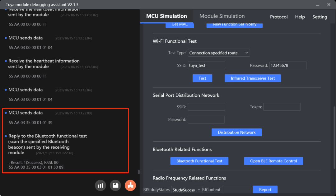
Test Bluetooth functionality
mcu_start_BLE_test() in mcu_api.c is used for the MCU to initiate a Bluetooth functionality test.
The process is as follows:
-
Enable
BLE_RELATED_FUNCTION_ENABLEto turn on Bluetooth functionalities.#define BLE_RELATED_FUNCTION_ENABLE // Turn on Bluetooth functionalities. -
The MCU calls
mcu_start_BLE_test()to enable scanning for the specified Bluetooth identifier./** * @brief The MCU initiates a functionality test on scanning for the specified Bluetooth identifier. * @param Null * @return Null * @note To be implemented by you. */ void mcu_start_BLE_test(void) { unsigned short send_len = 0; send_len = set_wifi_uart_byte(send_len, 0x01); wifi_uart_write_frame(BLE_TEST_CMD, MCU_TX_VER, send_len); } -
The MCU gets the test result from
data_handle()and callsBLE_test_result()to process the result.void data_handle(unsigned short offset) { ...... #ifdef BLE_RELATED_FUNCTION_ENABLE case BLE_TEST_CMD: //Scan for the specified Bluetooth identifier. total_len = (wifi_data_process_buf[offset + LENGTH_HIGH] << 8) | wifi_data_process_buf[offset + LENGTH_LOW]; BLE_test_result((unsigned char *)(wifi_data_process_buf + offset + DATA_START), total_len); break; #endif ...... } -
You need to implement the function
BLE_test_resultinprotocol.c./** * @brief Get the Bluetooth functionality test result. * @param[in] {value} The buffer. * @param[in] {length} The data length. * @return Null * @note To be implemented by you. */ void BLE_test_result(const unsigned char value[], unsigned short length) { #error "Complete the code for test results and then delete this row" unsigned char sub_cmd = value[0]; if(0x03 != length) { //Data length error. return; } if(0x01 != sub_cmd) { //Subcommand error. return; } unsigned char result = value[1]; unsigned char rssi = value[2]; if(result == 0) { //Test failed. if(rssi == 0x00) { // The Bluetooth identifier named `ty_mdev` is not found. }else if(rssi == 0x01) { // The module is not authorized. } }else if(result == 0x01) { //Test succeeded. // RSSI indicates the signal strength, ranging from 0 to 100. 0 represents the weakest, and 100 represents the strongest. } } -
Module Debugging Assistant
Is this page helpful?
YesFeedbackIs this page helpful?
YesFeedback


