Protocol Parsing
This topic describes protocol formats used in the general Wi-Fi solutions and the commands included in the basic and functional protocols.
This documentation is no longer updated. For more information, see Serial Communication Protocol.
Overview
This topic describes the required commands during module initialization and some commonly used commands for extended functions. For other commands, see Serial Port Protocol.
- Basic protocol: It is the function command of the module itself, irrelevant to the product function.
- Functional protocol: It is the data transmission command for each data point.
Protocol format
The MCU and the Wi-Fi module communicate through a serial port. The communication convention, data frame format, and command index are as follows.
Serial communication convention
| Parameter | Description |
|---|---|
| Baud | Depending on the firmware configuration, the Baud 9600 or 115200 is supported. |
| Data bit | 8 bits |
| Parity check | None |
| Stop bit | 1 bit |
| Data flow control | None |
Data frame format
| Field | Length (byte) | Description |
|---|---|---|
| Header | 2 | It is fixed as 0x55aa |
| Version | 1 | Protocol version number |
| Command | 1 | Frame type |
| Data length | 2 | Big-endian |
| Data | 1–2 | Custom data |
| Checksum | 1 | Start from the header, add up all the bytes, and then divide the sum by 256 to get the remainder |
Command index
| Command | Description |
|---|---|
| 0x00 | Detect the heartbeat |
| 0x01 | Query product information |
| 0x02 | Query working mode of the module |
| 0x03 | Report the network status of the device |
| 0x04 | Reset Wi-Fi |
| 0x05 | Reset Wi-Fi and switch network pairing mode |
| 0x06 | Send the DP commands |
| 0x07 | Report the DP status |
| 0x08 | Query the status |
| 0x0a | Start OTA updates (optional) |
| 0x0b | Transfer OTA update package (optional) |
| 0x1c | Get the local time (optional) |
| 0x0e | Test the Wi-Fi function |
Basic protocol
The basic protocol is indispensable for the work of the module.
- Basic functions of the module: Command
0x00–0x08to detect the heartbeat, query product information, query the working mode of the module, and more. - Extended functions of the module: Command
0x0a–0x0eto implement MCU OTA updates, get the local time, test Wi-Fi function, and more.
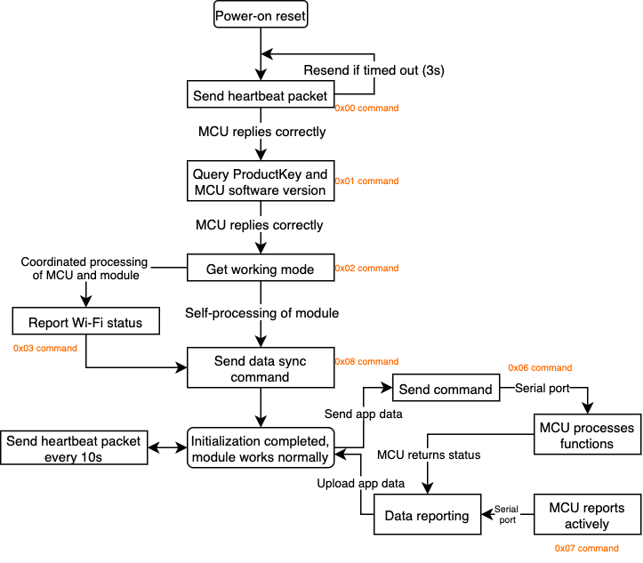
Module initialization
After power-on, the module continuously sends heartbeat packets. After the MCU responds to the heartbeat, the module starts the initialization process as shown in the following figure.
There are two processing modes:
- Self-processing mode of the module: The Wi-Fi reset button and Wi-Fi status indicator are on the Wi-Fi Module.
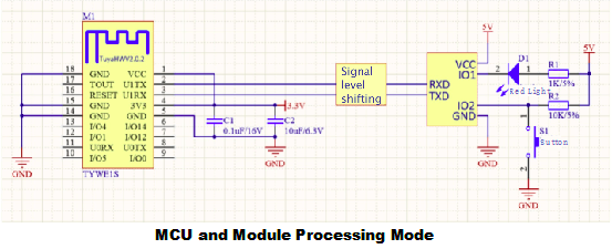
- Coordinated processing mode of the MCU and the module: The Wi-Fi reset button and Wi-Fi status indicator are on the MCU.
Baud rate adaptive:
The latest firmware of the module has added the function of adaptive baud rate detection, which can be adaptive to judge 9600/115200 baud rate. Therefore, before the initialization process, the module will go through the baud rate detection, and it is normal to receive some messy codes or delay the initial startup time.
The related process is as follows.
-
The module reads the baud rate record data stored in Flash.
-
Enter the relevant process according to whether the data can be read or not.
- If the data can be read: give priority to the combination and send 3 handshake packets, each about 1 second apart. If no reply, re-enter the scan mode.
- If data cannot be read: enter scan mode, switch between 9600 and 115200 (300~400ms), and send 2 packets for each combination. If the specified reply frame is received, the recognition is successful. The combination is then used to initialize the serial port and save the combination parameters to Flash, while the reply frames are saved and processed.
Command description
-
Detect the heartbeat
After power-on, the module sends heartbeat packets, and the MCU returns the
0x00or0x01command.0x00: The reply to the first heartbeat packet after power-on is0x00. After receiving the reply, the module starts to synchronize the initialization data.0x01: The reply to the second and further heartbeat packet is0x01. Check whether the device is offline or disconnected from the network.
Type Header Version Command Data length Data Checksum The module sends: 0x55aa 0x00 0x00 0x0000 None 0xff The MCU returns: 0x55aa 0x03 0x00 0x0001 - The first time: 0x00
- The second time and afterward: 0x01
{Checksum} For example,
- The module sends:
55 aa 00 00 00 00 ff - The MCU returns:
- The first time:
55 aa 03 00 00 01 00 03 - The second time and afterward:
55 aa 03 00 00 01 01 04
- The first time:
-
Query product information
After receiving the response from the MCU, the module will send a command to query the product information. The MCU returns information about PID, version, and mode.
Note:
{}:""and other characters shall also be entered.Type Header Version Command Data length Data Checksum The module sends: 0x55aa 0x00 0x01 0x0000 None 0x00 The MCU returns: 0x55aa 0x03 0x01 No limitation on the data length. For example, 0x002a.For example, {"p":”RN2FVAgXG6W****”,"v":”1.0.0”,”m”}. The following modes are supported:- 0: default network pairing
- 1: low power consumption
- 2: special network pairing
{Checksum} For example,
- The module sends:
55 aa 00 01 00 00 00 - The MCU returns:
55 aa 03 01 00 2a 7b 22 70 22 3a 22 52 4e 32 46 56 41 67 58 47 36 57 66 41 6b 74 55 22 2c 22 76 22 3a 22 31 2e 30 2e 30 22 2c 22 6d 22 3a 30 7d 0cNote: Convert each character (including punctuation marks) in
{"p":"RN2FVAgXG6W****","v":"1.0.0","m"}into ASCII code, and enter it in the data position.
-
Query working mode of the module
After receiving the product information, the module will send the
0x02command to query the working mode of the module that is set by the MCU. The working mode of the module includes Wi-Fi working status indication and Wi-Fi network reset. There are two cases:-
The coordinated processing mode of the MCU and the module
-
Indicate the pairing status: The module notifies the MCU of the current working status of Wi-Fi through the serial port, and the MCU controls the pairing indicator.
-
Reported data:
0.
-
-
The self-processing mode of the module
Note: The module self-processing mode skips the three steps in the initialization process, including reporting device networking status, resetting Wi-Fi, and resetting Wi-Fi, and switching pairing mode.
- Indicate the pairing status: Indicate the LED status by driving the Wi-Fi GPIO pin.
- Report data: I/O port data of the indicator and the button.
- Reset method: Wi-Fi detects the low level of GPIO input pin for more than five seconds to trigger the Wi-Fi reset. The GPIO pins used by the indicators and buttons are configured by the following commands.
Type Header Version Command Data length Data Checksum The module sends: 0x55aa 0x00 0x02 0x0000 None 0x01 The MCU returns (the coordinated processing mode of the MCU and the module): 0x55aa 0x03 0x02 0x0000 None {Checksum} The MCU returns (the self-processing mode of the module): 0x55aa 0x03 0x02 0x0002 - The first byte: GPIO serial number of the Wi-Fi status indicator.
- The second byte: GPIO serial number of the Wi-Fi reset button.
{Checksum} 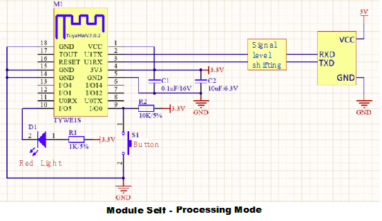
For example,
- The module sends:
55 aa 00 02 00 00 01 - The MCU returns:
- The coordinated processing mode of the MCU and the module:
55 aa 03 02 00 00 04. - The self-processing mode of the module:
55 aa 03 02 00 02 05 00 0b, where the indicator light is connected to I/O5, and the button is connected to I/O0.
- The coordinated processing mode of the MCU and the module:
-
-
Report the Wi-Fi status
Note: Only the coordinated processing mode of the MCU and the module supports this function.
When the module detects MCU reboots or Wi-Fi status changes of the module, the module actively sends the status to the MCU. The MCU can control the blinking of the indicator according to the Wi-Fi status in the
0x03command. In protocol version 3, Wi-Fi has six kinds of status.Device network status Description Status value LED status Status 1 SmartConfig configuration status 0x00 Flicker quickly at an interval of 250 ms Status 2 AP configuration status 0x01 Flicker slowly at an interval of 1,500 ms Status 3 Wi-Fi has been configured, but not connected to the router 0x02 Off Status 4 Wi-Fi has been configured, and connected to the router 0x03 Always on Status 5 Wi-Fi has been connected to the router and the cloud 0x04 Always on Status 6 The Wi-Fi device is in the low power consumption mode 0x05 Off Status 7 The Wi-Fi device is in the SmartConfig mode and AP configuration mode 0x05 Off Type Header Version Command Data length Data Checksum The module sends: 0x55aa 0x00 0x03 0x0001 The following status values are supported: - 0x00: SmartConfig pairing mode.
- 0x01: AP pairing mode.
- 0x02: Wi-Fi has been configured, but not connected to the router.
- 0x03: Wi-Fi has been configured, and connected to the router.
- 0x04: Wi-Fi has been connected to the router and the cloud.
- 0x05: The Wi-Fi device is in the low power consumption mode.
- 0x06: The Wi-Fi device is in the SmartConfig mode and AP configuration mode.
{Checksum} The MCU returns: 0x55aa 0x03 0x03 0x0000 None 0x05 For example,
- The module sends:
55 aa 00 03 00 01 01 {checksum} - The MCU returns:
55 aa 03 03 00 00 05
-
Reset Wi-Fi.
Note: Only the coordinated processing mode of the MCU and the module supports this function.
With the pairing command, the Wi-Fi can be reset, so the device is waiting to be paired. There are two pairing modes:
- SmartConfig mode: Quick flickering mode, which is simple and quick.
- AP mode: Slow flickering mode, which is stable and reliable.
Note: It is recommended that both modes be developed to meet different needs. The trigger mechanism of the pairing mode can be customized and distinguished by the fast flickering and slow flickering of the indicator.
Each time the MCU sends the
0x04command, the module switches to the other pairing mode. The default configuration is SmartConfig mode for the first time and then switches back and forth between SmartConfig mode and AP mode.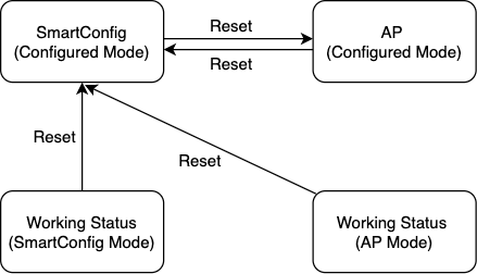
Type Header Version Command Data length Data Checksum The MCU sends: 0x55aa 0x00 0x04 0x0000 None 0x03 The module returns: 0x55aa 0x03 0x04 0x0000 None 0x06 For example,
- The MCU sends:
55 aa 03 04 00 00 06 - The module returns:
55 aa 00 04 00 00 03
-
Reset the Wi-Fi and select a pairing mode
Note: Only the coordinated processing mode of the MCU and the module supports this function.
Reset the Wi-Fi and select a pairing mode. Depending on the parameters sent by the MCU, specify to enter SmartConfig mode or AP mode. This command has the same function as the
0x04command. Both can be used for pairing, but this command can specify to enter a certain pairing mode.Type Header Version Command Data length Data Checksum The MCU sends (SmartConfig mode): 0x55aa 0x03 0x05 0x0001 0x00 {Checksum} The MCU sends (AP mode): 0x55aa 0x03 0x05 0x0001 0x01 {Checksum} The module returns: 0x55aa 0x00 0x05 0x0000 None 0x04 For example,
- The MCU sends:
- SmartConfig mode:
55 aa 03 05 00 01 00 08 - AP mode:
55 aa 03 05 00 01 01 09
- SmartConfig mode:
- The module returns:
55 aa 00 05 00 00 04
- The MCU sends:
-
Query working status of the MCU
With the
0x08command, the module gets the status of all the data points of the MCU and sets them to the initial values that are displayed on the app. After receiving the0x08command, the MCU reports all the DP data at one time or several times. The status query is sent at two-time points:- The module is powered on for the first time. After connecting to the MCU through the heartbeat, the module sends the query.
- When the module detects that the MCU reboots or is disconnected and then goes back online, the module sends the query.
Type Header Version Command Data length Data Checksum The module sends: 0x55aa 0x00 0x08 0x0000 None {Checksum} The MCU returns: 0x55aa 0x03 0x07 Unlimited Report all DP data as the initial value displayed {Checksum} For example,
- The module sends:
55 aa 00 08 00 00 07 - The MCU returns:
55 aa 03 07 N \***\* {checksum}(DP1)55 aa 03 07 N \*\*** {checksum}(DP2)- …(DPN)
-
Production test command
It is used to test the radio frequency performance of Wi-Fi modules during mass production. It is recommended to call the production test command five seconds after the power-on initialization is completed. After the module receives the production test command, the module will automatically scan the Wi-Fi signal named
tuya_mdev_test, and return the scan result and signal strength percentage, ranging from 0 to 100 with a step of 20.Type Header Version Command Data length Data Checksum The MCU sends: 0x55aa 0x03 0x0e 0x0000 None {Checksum} The module returns: 0x55aa 0x00 0x0e 0x0002 - The first byte: Whether the test is successful
- 0x00: failure
- 0x01: success
- The second byte: Wi-Fi signal strength percentage
{Checksum} For example,
- The MCU sends:
55 aa 03 0e 00 00 {checksum} - The module returns:
55 aa 00 0e 00 02 01 28 38, representing that the production test is successful and the signal strength is 40.
- The first byte: Whether the test is successful
Functional protocol
The module sends the 0x06 command, and the MCU reports the 0x07command. After receiving the data sending command, the MCU performs corresponding logic control according to the received functional command data and reports timely when the DP status changes, in order to change the display status on the app. If the data of one DP is the same as the last reported data, the module will filter out the data.
Example
| DP ID | DP name | Data transmission type | Data type | Remark |
|---|---|---|---|---|
| 3 | Current temperature | Report only | value | Value range: -20°C to 50°C at the interval of 1 |
| 4 | Working mode | Send and report | enum | Enumeration range: smart and auto |
| 21 | Fault alert | Report only | bitmap | Tag: motor_fault |
| 23 | Weekly schedules of the mode | Send and report | raw | Max length: 128 |
-
Value data: 4 bytes. If you use less than 4 bytes, just add 0 at the front.
Note: For example, in the current temperature, the MCU sends:
55 aa 03 07 00 08 02 02 00 04 00 00 00 1e {checksum}. The target temperature is 30°C. -
Bitmap data: Simultaneous reporting of multiple faults is supported. Each bit can represent a warning. 1 indicates failure occurred, and 0 indicates good conditions. It can be 1, 2, or 4 bytes. When it is larger than 1 byte, it is the big-endian mode.
Note: For example, if a fault warning occurs, the MCU sends:
55 aa 03 07 00 06 0d 05 00 02 00 09 {checksum}. Fault bit0 and fault bit3 occurred. -
String data: The meaning and display of the string shall be matched with the panel. For custom panels, submit a service ticket.
-
Raw data: It is usually used to implement more complex functions. Users are not recommended to use it by themselves.
Is this page helpful?
YesFeedbackIs this page helpful?
YesFeedback


