Serial Communication Protocol
This topic describes the serial protocol that is used to implement serial communication between Tuya’s Wi-Fi module or Wi-Fi and Bluetooth Low Energy (LE) combo module and the third-party MCU.
Serial communication
- Baud: 9600/115200
- Data bit: 8
- Parity check: none
- Stop bit: 1
- Data flow control: none
- MCU: microcontroller unit. Your MCU communicates with Tuya’s modules through the serial port.
Frame format
| Field | Bytes | Description |
|---|---|---|
| Header | 2 | It is fixed to 0x55aa. |
| Version | 1 | It is used for updates and extensions. |
| Command | 1 | Frame type |
| Data length | 2 | Big-endian |
| Data | N | Entity data |
| Checksum | 1 | Start from the header, add up all the bytes, and then divide the sum by 256 to get the remainder. |
-
All data greater than one byte is transmitted in big-endian format.
-
Generally, one command is sent by one party and received by the other party synchronously.
That is, one party sends a command and waits for a response from the other party. If the sender does not receive a correct response packet within a specified time period, the transmission times out, as shown in the following figure.
For more information, see Protocol list.
-
The module sends control commands and the MCU reports data point (DP) status, which occurs asynchronously. Assume that the module sends a command
Xand the MCU reports a commandY. The data transmission is as follows.-
The module sends a control command:
-
The MCU reports status:
-
-
The version field
The version number is used to distinguish between the old and legacy version. To provide compatibility with new and legacy protocols, the module queries the MCU version using the command
0x00and determines which protocol version it should use accordingly. The new protocol defaults to0x03.
Serial buffer size of module
| Chipset platform | Size of the receive buffer | Size of the send buffer | Notes |
|---|---|---|---|
| ESP8266 | 256 bytes | 256 bytes | The buffer size is fixed. |
| Others | A minimum of 1,024 bytes | A minimum of 1,024 bytes | If the firmware supports the file transfer feature, the maximum buffer size depends on the maximum size of a single packet transmitted. |
The length of the whole packet (including all bytes from header to checksum) sent from the MCU to the module must not exceed the maximum size of the receive buffer of the module. Otherwise, transmission errors might occur.
Data units
The DP command and status data units are defined as follows:
| Data segment | Bytes | Description |
|---|---|---|
| dpid | 1 | The ID of a DP. |
| type | 1 | The data type of a DP defined on the Tuya Developer Platform. For more information, see the description of the type fields in the following table. |
| len | 2 | The bytes of a value. For more information, see the description of the type fields in the following table. |
| Value | 1/2/4/N | Represented in hexadecimal format. Data greater than one byte is transmitted in big-endian format. |
Description of the type fields
| type | Data type | Bytes | Description |
|---|---|---|---|
| 0x00 | Raw | N | Represents a DP of raw data type. The data is passed through the module to the cloud. |
| 0x01 | Boolean | 1 | Represents a DP of Boolean data type. Valid values include 0x00 and 0x01. |
| 0x02 | Value | 4 | Represents a DP of integer type. The data is represented in big-endian format. |
| 0x03 | String | N | Represents a DP of string type. |
| 0x04 | Enum | 1 | Represents a DP of enum type, ranging from 0 to 255. |
| 0x05 | Bitmap | 1/2/4 | Represents a DP of fault type. Data greater than one byte is represented in big-endian format. |
- Except for the
rawdata type, all others belong to theobjecttype. - The status data can contain data units of multiple DPs.
Protocol list
Send heartbeats
-
After the Wi-Fi module is powered on, it keeps sending a heartbeat to the MCU every one second and waits for a response. If the module receives a response to a heartbeat, it will send a heartbeat every 15 seconds and run the initialization command. Otherwise, the module will keep sending a heartbeat to the MCU every one second until receiving a response.
-
The MCU can determine whether the module works properly by detecting heartbeats. If the module fails to send a heartbeat, the MCU can use the reset pin to reset the module. If the MCU fails to respond to a heartbeat within three seconds, the module determines the MCU is offline.
The module sends the following command.
| Field | Bytes | Description |
|---|---|---|
| Header | 2 | 0x55aa |
| Version | 1 | 0x00 |
| Command | 1 | 0x00 |
| Data length | 2 | 0x0000 |
| Data | 0 | None |
| Checksum | 1 | Start from the header, add up all the bytes, and then divide the sum by 256 to get the remainder. |
For example, 55 aa 00 00 00 00 ff
The MCU returns the following command.
| Field | Bytes | Description |
|---|---|---|
| Header | 2 | 0x55aa |
| Version | 1 | 0x03 |
| Command | 1 | 0x00 |
| Data length | 2 | 0x0001 |
| Data | 1 |
|
| Checksum | 1 | Start from the header, add up all the bytes, and then divide the sum by 256 to get the remainder. |
- For example, the MCU returns
55 aa 03 00 00 01 00 03after a restart. - The MCU returns
55 aa 03 00 00 01 01 04except for the first response after a restart.
Query product information
Product information consists of the product ID and MCU software version number.
- Product ID (PID): It is automatically generated for each product created on the Tuya Developer Platform for storing product information in the cloud.
- MCU software version number: It is expressed in dot-decimal notation,
x.x.x.xis a decimal digit between 0 and 99.
The module sends the following command.
| Field | Bytes | Description |
|---|---|---|
| Header | 2 | 0x55aa |
| Version | 1 | 0x00 |
| Command | 1 | 0x01 |
| Data length | 2 | 0x0000 |
| Data | 0 | None |
| Checksum | 1 | Start from the header, add up all the bytes, and then divide the sum by 256 to get the remainder. |
For example, 55 aa 00 01 00 00 00
The MCU returns the following command.
| Field | Bytes | Description |
|---|---|---|
| Header | 2 | 0x55aa |
| Version | 1 | 0x03 |
| Command | 1 | 0x01 |
| Data length | 2 | N |
| Data | N | {"p":"AIp08kLIftb8x***", "v":"1.0.0", "m":1, "mt":10, "n":0, "ir":"5.12", "low":0} |
| Checksum | 1 | Start from the header, add up all the bytes, and then divide the sum by 256 to get the remainder. |
For example, {"p":"AIp08kLIftb8x***","v":"1.0.0","m":1,"mt":10,"n":0,"ir":"5.12","low":0}
Field description:
| Field | Description |
|---|---|
| p | Indicates the product ID is Ip08kLIftb8x***, which is the PID of a product created on the Tuya Developer Platform. |
| v | Indicates the MCU version is 1.0.0. The version number must be defined in the format x.x.x. |
| m | Indicates the operation mode of the module.
|
| mt | Indicates the switching time period between the safe mode and anti-misoperation mode. You can set a period between 3 and 10 minutes. If you leave this field empty, the period defaults to 3 minutes. |
| n | Indicates the network pairing mode. If you leave this field empty, the pairing mode is switched between the Wi-Fi Easy Connect (EZ) mode and the access point (AP) mode.
|
| ir | Used to enable the infrared (IR) feature and notify the module of the IR transmission (TX) pin and IR reception (RX) pin. If you leave this field empty, the IR feature is disabled. For example, 5.12 indicates the IR TX pin is I/O 5 and the IR RX pin is I/O 12.Note: If the module works in the self-processing mode, the IR I/Os must not be used for the reset button or the Wi-Fi status indicator. For cross-module I/O configuration, the pin number plus 32 makes the pin number we need. For example, the pin number to be set for PB20 is 52 (20 + 32 = 52). The IR TX pin requires PWM signals. The IR RX pin requires I/O interrupts. For more information about the pin configuration, see the datasheet of your modules.If you want to enable the IR status indicator, see (Optional) Notification of new feature setting and configure it. |
| low | Used to enable the low power mode. If you leave this field empty, the low power mode is disabled. In low power mode, when a device is connected to the router but not executing any commands, its power consumption can be lower than 15 mA on average. When the Wi-Fi and Bluetooth combo module runs in low power mode, it only supports Bluetooth pairing without device control. If power consumption is not your concern, you can leave this field as is.
|
| vt | Indicates the MCU firmware type, which defaults to 9. You can set a value between 10 and 19 to specify a firmware type. Your specified value must match the value of the field Update Channel that appears when you add firmware on the Tuya Developer Platform. |
The value of vt you specified in the SDK must be consistent with the value of Update Channel specified on the Tuya Developer Platform. Otherwise, the device cannot receive OTA updates or receives the wrong OTA updates.
Query working mode
The working mode means how the Wi-Fi status is indicated and the module is reset. Two modes are available.
-
The MCU works with the module to process network events.
When the MCU detects a pairing signal, it notifies the module of performing network reset through serial communication. The module sends the current Wi-Fi status to the MCU through serial communication. The MCU executes status indications accordingly. Home appliances usually use this mode.
-
The module processes network events itself.
The GPIO pin on the module drives the LED indicator to indicate the network status. The GPIO input signal determines module reset.
When the module detects a low level on the GPIO input pin for more than five seconds, it will trigger a reset action. The following command specifies the GPIO pins of the LED indicator and the reset button.
The module sends the following command.
| Field | Bytes | Description |
|---|---|---|
| Header | 2 | 0x55aa |
| Version | 1 | 0x00 |
| Command | 1 | 0x02 |
| Data length | 2 | 0x0000 |
| Data | 0 | None |
| Checksum | 1 | Start from the header, add up all the bytes, and then divide the sum by 256 to get the remainder. |
For example, 55 aa 00 02 00 00 01
The MCU returns the following command.
| Field | Bytes | Description |
|---|---|---|
| Header | 2 | 0x55aa |
| Version | 1 | 0x03 |
| Command | 1 | 0x02 |
| Data length | 2 |
|
| Data | 0/2/3 | The data length is 2 bytes. The first byte represents the GPIO pin used to indicate Wi-Fi status. The second byte represents the GPIO pin used to reset the Wi-Fi network. |
| Data | 0/2/3 | If data length is 2 bytes:
|
| Checksum | 1 | Start from the header, add up all the bytes, and then divide the sum by 256 to get the remainder. |
Example:
-
The MCU works with the module to process network events.
55 aa 03 02 00 00 04 -
The module processes network events itself.
0x0cindicates the LED indicator is connected to GPIO12.0x0dindicates the reset button is connected to GPIO13.55 aa 03 02 00 02 0c 0d 1f
(Optional) Notification of new feature setting
- After the device is powered on, the MCU sends this command to notify the module of feature configuration after the command
0x01and before the command0x02. - If no new feature configuration is required, the MCU does not need to send this command.
- The MCU must send this command each time after the module is powered on or the module is restarted.
- The fields of this command will be added as the service is extended.
-
ir: IR status indicator. It can share the same GPIO pin with the Wi-Fi status indicator but must not conflict with other GPIOs associated with the command0x02. The IR status indicator is defined as follows.- Sharing the same GPIO pin with the Wi-Fi status indicator: The LED is on when the IR is idle. The LED is off when the IR is used.
- Using an individual GPIO pin: The LED is on when the IR is used. The LED is off when the IR is idle.
-
buf: the maximum buffer size of the MCU serial port. For the RF remote control feature, when multiple key values are transmitted, the buffer size depends on whether key values are transmitted using multiple packets. -
RF remote control: the 433 MHz RF remote controls developed with the Tuya standard RF solution.
For the RF remote control feature, when multiple key values are transmitted, the buffer size depends on whether key values are transmitted using multiple packets.
The MCU sends the following command.
| Field | Bytes | Description |
|---|---|---|
| Header | 2 | 0x55aa |
| Version | 1 | 0x03 |
| Command | 1 | 0x37 |
| Data length | 2 | 0x0001 |
| Data | 1 | Subcommand: 0x00 |
| { "mcu_ota":xx, "abv":x, "ir":xx, "buf":xx } |
|
|
| Checksum | 1 | Start from the header, add up all the bytes, and then divide the sum by 256 to get the remainder. |
For example, if the MCU has a scratchpad, the RF remote control is enabled, and the buffer size is 1024 bytes, the MCU sends the following command. {"mcu_ota":0,"abv":3,"buf":1024}
55 aa 03 37 00 21 00 7b 22 6d 63 75 5f 6f 74 61 22 3a 30 2c 22 61 62 76 22 3a 33 2c 22 62 75 66 22 3a 31 30 32 34 7d ac
The module returns the following command.
| Field | Bytes | Description |
|---|---|---|
| Header | 2 | 0x55aa |
| Version | 1 | 0x00 |
| Command | 1 | 0x37 |
| Data length | 2 | 0x0002 |
| Data | 1 | Subcommand: 0x00 |
| 1 | 0x00: success. 0x01: invalid data. 0x02: failure. |
|
| Checksum | 1 | Start from the header, add up all the bytes, and then divide the sum by 256 to get the remainder. |
For example, 55 aa 03 37 00 02 00 00 3b
Field description:
| Field | Required | Description |
|---|---|---|
| mcu_ota | No | Specifies whether an MCU has a scratchpad. This field only applies to HomeKit accessories currently. |
| abv | No | Enables new features. Each bit represents a feature.
|
| ir | No | Sets the GPIO pin used for IR status indicator in the module self-processing mode. The data content follows the definition of the command 0x02. For example, 5 indicates the GPIO 5 is used for IR status indicator. |
| buf | No | The MCU serial receive buffer, with a minimum size of 256 bytes. |
Report network status
| Network status | Description | Status value |
|---|---|---|
| Status 1 | Pairing in EZ mode (For Wi-Fi and Bluetooth LE combo module: Bluetooth is also in pairing mode.) | 0x00 |
| Status 2 | Pairing in AP mode (For Wi-Fi and Bluetooth LE combo module: Bluetooth is also in pairing mode.) | 0x01 |
| Status 3 | The Wi-Fi network is set up, but the device is not connected to the router. | 0x02 |
| Status 4 | The Wi-Fi network is set up, and the device is connected to the router. | 0x03 |
| Status 5 | The device is connected to the cloud. | 0x04 |
| Status 6 | Tuya’s network module is in low power mode. | 0x05 |
| Status 7 | EZ mode and AP mode coexist. (For Wi-Fi and Bluetooth LE combo module: Bluetooth is also in pairing mode.) | 0x06 |
-
Network status
- Pairing in EZ mode (For Wi-Fi and Bluetooth LE combo module: Bluetooth is also in pairing mode.)
- Pairing in AP mode (For Wi-Fi and Bluetooth LE combo module: Bluetooth is also in pairing mode.)
- The Wi-Fi network is set up, but the device is not connected to the router.
- The Wi-Fi network is set up, and the device is connected to the router.
- The device is connected to the cloud.
-
The LED activity in the module self-processing mode.
- Status 1: blinking every 250 ms.
- Status 2: blinking every 1,500 ms.
- Status 3 or 6: steady off.
- Status 4 or 5: steady on.
-
When the module detects that the MCU is restarted or reconnected, it will proactively send the current Wi-Fi status to the MCU.
-
When the network status changes, the module will proactively send the current status to the MCU.
-
If you choose the module self-processing mode, implementing this protocol for your MCU is not necessary.
- For devices using the Wi-Fi and Bluetooth LE combo module, when the network status is
0x00,0x01, or0x06, Bluetooth is also in pairing mode. - Network status
0x04indicates a device is successfully connected to the cloud either over Wi-Fi or Bluetooth. If the device is connected over Bluetooth, the Bluetooth status is required to determine whether this device can be controlled by the mobile app. - It is recommended to subscribe to Report Bluetooth connection status to notify users of the current Bluetooth status.
The module sends the following command.
| Field | Bytes | Description |
|---|---|---|
| Header | 2 | 0x55aa |
| Version | 1 | 0x00 |
| Command | 1 | 0x03 |
| Data length | 2 | 0x0001 |
| Data | 1 | Indicates Wi-Fi status.
|
| Checksum | 1 | Start from the header, add up all the bytes, and then divide the sum by 256 to get the remainder. |
For example, 55 aa 00 03 00 01 00 03
The MCU returns the following command.
| Field | Bytes | Description |
|---|---|---|
| Header | 2 | 0x55aa |
| Version | 1 | 0x03 |
| Command | 1 | 0x03 |
| Data length | 2 | 0x0000 |
| Data | 0 | None |
| Checksum | 1 | Start from the header, add up all the bytes, and then divide the sum by 256 to get the remainder. |
For example, 55 aa 03 03 00 00 05
Reset Wi-Fi connection
When receiving a reset command, the module will restart, perform an initialization operation, and enter the pairing mode.
-
The following figure shows how the working status of the module changes after a reset.
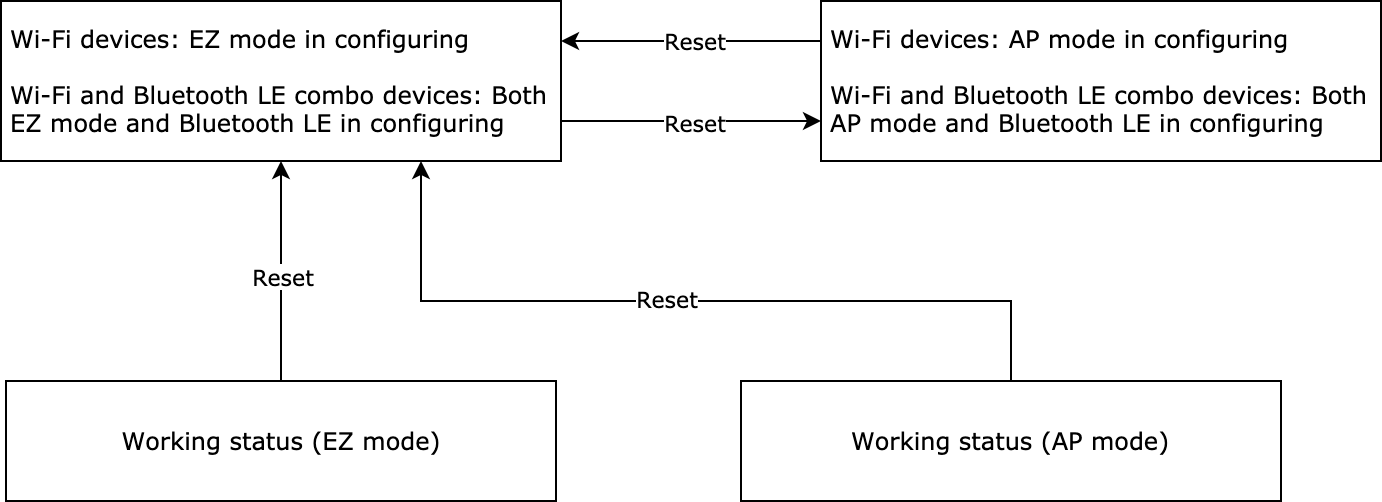
- The reset command must be sent after the module initialization is completed. Otherwise, the reset might not work. For more information, see Module initialization.
- After the Wi-Fi and Bluetooth LE combo module receives the reset command, both the Wi-Fi and Bluetooth LE networks are reset and ready for connection.
-
If you choose the module self-processing mode, implementing this protocol for your MCU is not necessary.
When the module detects a low level on the GPIO input pin for more than five seconds, it will trigger a reset action.
The MCU sends the following command.
| Field | Bytes | Description |
|---|---|---|
| Header | 2 | 0x55aa |
| Version | 1 | 0x03 |
| Command | 1 | 0x04 |
| Data length | 2 | 0x0000 |
| Data | 0 | None |
| Checksum | 1 | Start from the header, add up all the bytes, and then divide the sum by 256 to get the remainder. |
For example, 55 aa 03 04 00 00 06
The module returns the following command.
| Field | Bytes | Description |
|---|---|---|
| Header | 2 | 0x55aa |
| Version | 1 | 0x00 |
| Command | 1 | 0x04 |
| Data length | 2 | 0x0000 |
| Data | 0 | None |
| Checksum | 1 | Start from the header, add up all the bytes, and then divide the sum by 256 to get the remainder. |
For example, 55 aa 00 04 00 00 03
Reset Wi-Fi and select pairing mode
This command is similar to the previous one of resetting the Wi-Fi connection.
-
The difference lies in that this command allows the MCU to select a pairing mode after the network is reset.
-
You can implement this protocol as needed.
-
If you choose the module self-processing mode, implementing this protocol for your MCU is not necessary.
- The reset command must be sent after the module initialization is completed. Otherwise, the reset might not work. For more information, see Module initialization.
- If the MCU sets the
nfield in Query product information, the pairing mode specified by this command does not work.
The MCU sends the following command.
| Field | Bytes | Description |
|---|---|---|
| Header | 2 | 0x55aa |
| Version | 1 | 0x03 |
| Command | 1 | 0x05 |
| Data length | 2 | 0x0001 |
| Data | 1 |
|
| Checksum | 1 | Start from the header, add up all the bytes, and then divide the sum by 256 to get the remainder. |
For example, to enter EZ mode, the MCU will send the following command.
55 aa 03 05 00 01 00 08
The module returns the following command.
| Field | Bytes | Description |
|---|---|---|
| Header | 2 | 0x55aa |
| Version | 1 | 0x00 |
| Command | 1 | 0x05 |
| Data length | 2 | 0x0000 |
| Data | 0 | None |
| Checksum | 1 | Start from the header, add up all the bytes, and then divide the sum by 256 to get the remainder. |
For example, 55 aa 00 05 00 00 04
Send commands
-
The command sent by the module can contain Data units of multiple DPs.
-
The command sending is processed asynchronously. The module parses the received data and sends it to the MCU. The MCU executes the command accordingly and reports the changed DP status if required.
The module sends the following command.
| Field | Bytes | Description |
|---|---|---|
| Header | 2 | 0x55aa |
| Version | 1 | 0x00 |
| Command | 1 | 0x06 |
| Data length | 2 | Depends on the type and number of data units. |
| Data | N | Data units |
| Checksum | 1 | Start from the header, add up all the bytes, and then divide the sum by 256 to get the remainder. |
For example, if DP 3 of a boolean type is used for on/off control, and 1 means to turn on the device, the module will send the following command.
55 aa 00 06 00 05 03 01 00 01 01 10
Report status (async)
-
This is an asynchronous command. The MCU uses it to report DP status to the module, which can be triggered by three mechanisms.
- After the MCU executes the command received from the module, it reports the changed DP status to the module.
- When the MCU proactively detects status changes of DPs, it reports the changed DP status to the module.
- When the MCU receives the DP status query, it sends the status of all DPs to the module.
-
The MCU can report the status of multiple DPs. For more information about the DP status data unit, see Data units.
- It is recommended to report the status of a DP when it is changed to ensure stable data transmission. Try to avoid frequent status reporting for a short period of time.
- If you have multiple DPs to report, it is recommended to report them in one packet. For reporting a single DP, set the reporting interval to at least 250 milliseconds for stable data transmission.
- When the device is in the idle or stable state, make sure the frequency of reporting the status of the same DP is appropriate. The recommended minimum interval is one minute.
- The DP that the MCU reports must match the PID’s DP defined on the Tuya Developer Platform. The PID is the value of the
pfield that the MCU returns on the product information query. The MCU must not report any DP that does not exist. - The DP ID, data type, and payload of the DP that the MCU reports must match the PID’s DP defined on the Tuya Developer Platform. The PID is the value of the
pfield that the MCU returns on the product information query.
The MCU sends the following command.
| Field | Bytes | Description |
|---|---|---|
| Header | 2 | 0x55aa |
| Version | 1 | 0x03 |
| Command | 1 | 0x07 |
| Data length | 2 | It depends on the types and the number of data units. |
| Data | N | Data units |
| Checksum | 1 | Start from the header, add up all the bytes, and then divide the sum by 256 to get the remainder. |
For example, if DP 5 of a value type is used for reporting the current humidity, and the current humidity is 30%, the MCU will send the following data to the module.
55 aa 03 07 00 08 05 02 00 04 00 00 00 1e 3a
Report data units of multiple DPs:
The DP 109 is of Boolean data type, and its value is 1.
The DP 102 is of string data type, and its value is 201804121507. The value is transferred in ASCII mode.
The MCU will send the following data to the module.
55 aa 03 07 00 15 6d 01 00 01 01 66 03 00 0c 32 30 31 38 30 34 31 32 31 35 30 37 62
Report status (sync)
-
This is a synchronous command. The MCU reports DP status and then waits for the result from the module.
-
The module must respond to each status reporting message. The MCU must not send a new reporting task until receiving a response from the module.
-
If the data fails to be reported to the cloud due to poor network quality, the module will return a failure code five seconds later. In this case, the MCU should wait for more than five seconds.
-
The MCU can report the status of multiple DPs. For more information about the DP status data unit, see Data units.
- It is recommended to report the status of a DP when it is changed to ensure stable data transmission. Try to avoid frequent status reporting for a short period of time.
- When the device is in the idle or stable state, make sure the frequency of reporting the status of the same DP is appropriate. The recommended minimum interval is one minute.
- The DP that the MCU reports must match the PID’s DP defined on the Tuya Developer Platform. The PID is the value of the
pfield that the MCU returns on the product information query. The MCU must not report any DP that does not exist. - The DP ID, data type, and payload of the DP that the MCU reports must match the PID’s DP defined on the Tuya Developer Platform. The PID is the value of the
pfield that the MCU returns on the product information query.
The MCU sends the following data.
| Field | Bytes | Description |
|---|---|---|
| Header | 2 | 0x55aa |
| Version | 1 | 0x03 |
| Command | 1 | 0x22 |
| Data length | 2 | It depends on the types and the number of data units. |
| Data | N | Data units |
| Checksum | 1 | Start from the header, add up all the bytes, and then divide the sum by 256 to get the remainder. |
For example, the status of Boolean DP 1 is true, the MCU reports the following data to the module:
55 aa 03 22 00 05 02 01 00 01 01 2e
The module returns the following data.
| Field | Bytes | Description |
|---|---|---|
| Header | 2 | 0x55aa |
| Version | 1 | 0x00 |
| Command | 1 | 0x23 |
| Data length | 2 | 0x0001 |
| Data | Data |
|
| Checksum | 1 | Start from the header, add up all the bytes, and then divide the sum by 256 to get the remainder. |
For example, the module returns 55 aa 00 23 00 01 01 24.
Report status (record-type)
-
This is a synchronous command. The MCU reports DP status and then waits for the result from the module.
-
The module must respond to each status reporting message. The MCU must not send a new reporting task until receiving a response from the module.
-
If the data fails to be reported to the cloud due to poor network quality, the module will return a failure code five seconds later. In this case, the MCU should wait for more than five seconds.
-
The MCU can report the status of multiple DPs. For more information about the DP status data unit, see Data units.
-
For devices with records or metering features, such as door locks and smart plugs with energy monitoring, you can use this command to report the status of the corresponding DPs. If a single record message contains the status of multiple DPs, it should be reported in one packet.
-
This type of status reporting only applies to Wi-Fi protocol currently. The Bluetooth protocol support for this type of status reporting will be added in the firmware update in the future.
-
Before using this type of status reporting, check if the current firmware supports it.
- The module does not cache the data that fails to be reported.
- It is recommended to report the status of a DP when it is changed to ensure stable data transmission. Try to avoid frequent status reporting for a short period of time.
- If you have multiple DPs to report, it is recommended to report them in one packet. For reporting a single DP, set the reporting interval to at least 250 milliseconds for stable data transmission.
- When the device is in the idle or stable state, make sure the frequency of reporting the status of the same DP is appropriate. The recommended minimum interval is one minute.
- The DP that the MCU reports must match the PID’s DP defined on the Tuya Developer Platform. The PID is the value of the
pfield that the MCU returns on the product information query. The MCU must not report any DP that does not exist. - The DP ID, data type, and payload of the DP that the MCU reports must match the PID’s DP defined on the Tuya Developer Platform. The PID is the value of the
pfield that the MCU returns on the product information query.
The MCU sends the following data.
| Field | Length | Description |
|---|---|---|
| Header | 2 | 0x55aa |
| Version | 1 | 0x03 |
| Command | 1 | 0x34 |
| Data length | 2 | It depends on the types and the number of data units. |
| Data | 1 | 0x0b (subcommand) |
| 1 | 0x01 (default) | |
| 1 | The time data carried in the payload:
|
|
| 6 | Date and time format:
|
|
| N | Data units | |
| Checksum | 1 | Start from the header, add up all the bytes, and then divide the sum by 256 to get the remainder. |
For example, for the Boolean DP of DP ID 1, if its status is true, and the GMT is 2022.02.18.16:27:06, the MCU reports 55 aa 03 34 00 0e 0b 01 02 16 02 12 10 1b 06 01 01 00 01 01 b1 to the module.
For example, for the value DP of DP ID 2, its status is 100; for the enum DP of DP ID 3, its status is 3. If the local time is 2022.02.22.11:22:33, the MCU reports 55 aa 03 34 00 16 0b 01 01 16 02 16 0b 16 21 02 02 04 00 00 00 64 03 04 01 03 40 to the module.
The module returns the following data.
| Field | Length | Description |
|---|---|---|
| Header | 2 | 0x55aa |
| Version | 1 | 0x00 |
| Command | 1 | 0x34 |
| Data length | 2 | 0x0002 |
| Data | 1 | 0x0b (subcommand) |
| 1 | The result of status reporting:
|
|
| Checksum | 1 | Start from the header, add up all the bytes, and then divide the sum by 256 to get the remainder. |
For example, 55 aa 00 34 00 02 0b 00 40
Query DP status
-
The module asynchronously queries the status of all object DPs. When the MCU receives queries, it sends the status of DPs to the module. For more information, see Report status.
-
The module sends DP status queries when the following three events occur.
- When powered on for the first time, the module builds communication with the MCU and then sends status queries.
- When the module detects the MCU is restarted or disconnected and then goes online, the module sends status queries.
- To query the status of a device connected over Wi-Fi when the user opens the app panel, you need to enable Bit3 in the
abvfield.
- Check firmware compatibility with this feature. Update to the latest firmware version if necessary.
- The legacy firmware only supports sending status queries when the device is powered on for the first time.
The module sends the following command.
| Field | Bytes | Description |
|---|---|---|
| Header | 2 | 0x55aa |
| Version | 1 | 0x00 |
| Command | 1 | 0x08 |
| Data length | 2 | 0x0000 |
| Data | 0 | None |
| Checksum | 1 | Start from the header, add up all the bytes, and then divide the sum by 256 to get the remainder. |
For example, 55 aa 00 08 00 00 07
Update MCU firmware
-
You can specify the update method for OTA MCU firmware updates. The module only serves as the channel for OTA data transmission, without any data parsing operation.
-
The Tuya Developer Platform provides four update methods.
- Update notification: Users receive a firmware update notification on the app and choose whether to install updates.
- Automatic update: Users will not receive any update pop-up window. The module checks for firmware updates within one minute after power-on. If any new version is available, it will automatically pull the updates. The module checks for updates every 24 hours after the first-time power-on.
- Forced update: Users receive a firmware update notification on the app and have no option but to update the firmware.
- Check for updates: Users will not receive a firmware update notification on the app but need to manually check for new updates.
-
The following flowchart shows how the OTA firmware update works.
After the module has sent all update packages, it will send the command0x01to query the product information. The MCU must reply with the new MCU firmware version number within one minute. The new version number should be consistent with that configured on the Tuya Developer Platform.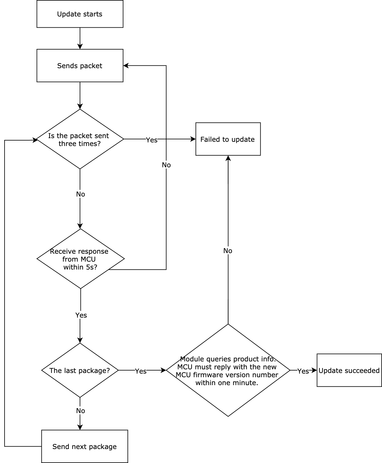
Start OTA update
The OTA update can be initiated automatically or manually. For automatic updates, when the module detects MCU firmware updates from the cloud, the transmission of the update package automatically starts. For manual updates, the module initiates updates only when updates are confirmed on the app.
The module sends the following command.
| Field | Bytes | Description |
|---|---|---|
| Header | 2 | 0x55aa |
| Version | 1 | 0x00 |
| Command | 1 | 0x0a |
| Data length | 2 | 0x0004 |
| Data | 4 | The size of the update package. The data type is an unsigned integer, and the data is stored in big-endian format. |
| Checksum | 1 | Start from the header, add up all the bytes, and then divide the sum by 256 to get the remainder. |
For example, 55 aa 00 0a 00 04 00 00 68 00 75
It indicates the size of the update package is 26624 bytes, namely 26 KB.
The MCU returns the following command.
| Field | Bytes | Description |
|---|---|---|
| Header | 2 | 0x55aa |
| Version | 1 | 0x03 |
| Command | 1 | 0x0a |
| Data length | 2 | 0x0001 |
| Data | 1 | The update package size of a single packet:
|
| Checksum | 1 | Start from the header, add up all the bytes, and then divide the sum by 256 to get the remainder. |
For example, 55 aa 03 0a 00 01 00 0d
Transmit update package
-
The data format of update package transmission: packet offset + packet data.
-
If the MCU receives the frame with a data length equal to 4 bytes and the packet offset is equal to or greater than the size of firmware, the transmission ends.
The module sends the following command.
| Field | Bytes | Description |
|---|---|---|
| Header | 2 | 0x55aa |
| Version | 1 | 0x00 |
| Command | 1 | 0x0b |
| Data length | 2 | 0x0004+N |
| Data | 4+N |
|
| Checksum | 1 | Start from the header, add up all the bytes, and then divide the sum by 256 to get the remainder. |
Example:
The size of the update file is 530 bytes. The MCU can skip the response to the last packet.
- For the first packet, the packet offset is
0x00000000, and the packet length is 256 bytes.
55 aa 00 0b 01 04 00000000 xx…xx XX - For the second packet, the packet offset is
0x00000100, and the packet length is 256 bytes.
55 aa 00 0b 01 04 00000100 xx…xx XX - For the third packet, the packet offset is
0x00000200, and the packet length is 18 bytes.
55 aa 00 0b 00 16 00000200 xx…xx XX - For the last packet, the packet offset is
0x00000212, and the packet length is 0 bytes.
55 aa 00 0b 00 04 00000212 xx…xx XX
The MCU returns the following command.
| Field | Bytes | Description |
|---|---|---|
| Header | 2 | 0x55aa |
| Version | 1 | 0x03 |
| Command | 1 | 0x0b |
| Data length | 2 | 0x0000 |
| Data | 0 | None |
| Checksum | 1 | Start from the header, add up all the bytes, and then divide the sum by 256 to get the remainder. |
For example, 55 aa 03 0b 00 00 0d
Get system time in GMT
-
As the international standard of civil time, GMT is independent of the time zone and DST.
-
After connecting to the network, the module returns success and valid time data after the local timestamp is synced.
- For a device using the Wi-Fi and Bluetooth LE combo module, the MCU can request the time data when it receives the Bluetooth status value of
0x03. When the device connects to the mobile app, the app must have access to the internet. - When the MCU receives the Wi-Fi status value of
0x04, the module will start syncing time with the time server. - If you do not want the MCU to proactively request time data after power on, you can turn on time service notification to enable the module to send the MCU time data after it finishes time sync.
- It takes time to sync time. If the MCU requests the time data immediately after receiving the network status from the module, the request might fail. In this case, the MCU should try to send the request again.
- For Wi-Fi and Bluetooth LE combo modules, only the latest firmware version supports time sync over Bluetooth.
- If time sync over Bluetooth does not work with the latest firmware version, submit a service ticket to request technical support.
- For a device using the Wi-Fi and Bluetooth LE combo module, the MCU can request the time data when it receives the Bluetooth status value of
The MCU sends the following command.
| Field | Bytes | Description |
|---|---|---|
| Header | 2 | 0x55aa |
| Version | 1 | 0x03 |
| Command | 1 | 0x0c |
| Data length | 2 | 0x0000 |
| Data | 0 | None |
| Checksum | 1 | Start from the header, add up all the bytes, and then divide the sum by 256 to get the remainder. |
For example, 55 aa 03 0c 00 00 0e
The module returns the following command.
| Field | Bytes | Description |
|---|---|---|
| Header | 2 | 0x55aa |
| Version | 1 | 0x00 |
| Command | 1 | 0x0c |
| Data length | 2 | 0x0007 |
| Data | 7 | The data length is 7 bytes.
|
| Checksum | 1 | Start from the header, add up all the bytes, and then divide the sum by 256 to get the remainder. |
For example, if the system time is 05:06:07 on April 19, 2016 (GMT), the module will return the following command.
55 aa 00 0c 00 07 01 10 04 13 05 06 07 4c
Get local time
- The local time is calculated by adding the time zone offset and DST to the GMT. The time zone is where the device is activated.
- After connecting to the network, the module returns success and valid time data after the local timestamp is synced.
- For a device using the Wi-Fi and Bluetooth LE combo module, the MCU can request the time data when it receives the Bluetooth status value of
0x03. When the device connects to the mobile app, the app must have access to the internet. - When the MCU receives the Wi-Fi status value of
0x04, the module will start syncing time with the time server. - If you do not want the MCU to proactively request time data after power on, you can turn on time service notification to enable the module to send the MCU time data after it finishes time sync.
- It takes time to sync time. If the MCU requests the time data immediately after receiving the network status from the module, the request might fail. In this case, the MCU should try to send the request again.
- For Wi-Fi and Bluetooth LE combo modules, only the latest firmware version supports time sync over Bluetooth.
- If time sync over Bluetooth does not work with the latest firmware version, submit a service ticket to request technical support.
The MCU sends the following command.
| Field | Bytes | Description |
|---|---|---|
| Header | 2 | 0x55aa |
| Version | 1 | 0x03 |
| Command | 1 | 0x1c |
| Data length | 2 | 0x0000 |
| Data | 0 | None |
| Checksum | 1 | Start from the header, add up all the bytes, and then divide the sum by 256 to get the remainder. |
For example, 55 aa 03 1c 00 00 1e
The module returns the following command.
| Field | Bytes | Description |
|---|---|---|
| Header | 2 | 0x55aa |
| Version | 1 | 0x00 |
| Command | 1 | 0x1c |
| Data length | 2 | 0x0008 |
| Data | 8 | The data length is 8 bytes.
|
| Checksum | 1 | Start from the header, add up all the bytes, and then divide the sum by 256 to get the remainder. |
-
If the device is activated in mainland China, the local time is Beijing time (GMT+08:00).
For example, if the local time is 05:06:07 on April 19, 2016 (GMT+08:00), the module will return the following command.
55 aa 00 1c 00 08 01 10 04 13 05 06 07 02 5f -
If the device is activated in other countries or regions, the local time is the time zone in which the device is located.
Test Wi-Fi functionality (scanning)
-
The module scans the router whose SSID is
tuya_mdev_testand returns the result and signal strength in percentage. -
To prevent quality defects, it is recommended that the distance between the router and the device under test should be about 5 meters. If the signal strength is greater than or equal to 60%, the device is acceptable. The specific testing conditions depend on your production line and environment.
The test command must be sent after the module initialization is completed. Otherwise, the command might not work. For more information, see Module initialization.
The MCU sends the following command.
| Field | Bytes | Description |
|---|---|---|
| Header | 2 | 0x55aa |
| Version | 1 | 0x03 |
| Command | 1 | 0x0e |
| Data length | 2 | 0x0000 |
| Data | 0 | None |
| Checksum | 1 | Start from the header, add up all the bytes, and then divide the sum by 256 to get the remainder. |
For example, 55 aa 03 0e 00 00 10
The module returns the following command.
| Field | Bytes | Description |
|---|---|---|
| Header | 2 | 0x55aa |
| Version | 1 | 0x00 |
| Command | 1 | 0x0e |
| Data length | 2 | 0x0002 |
| Data | 2 | The data length is 2 bytes. Data[0]: 0x00 indicates failure and 0x01 indicates success.
|
| Checksum | 1 | Start from the header, add up all the bytes, and then divide the sum by 256 to get the remainder. |
For example, if the module does not find the specified SSID, it returns 55 aa 00 0e 00 02 00 00 0f.
Get module’s memory
Get the remaining memory of the Wi-Fi module.
The MCU sends the following command.
| Field | Bytes | Description |
|---|---|---|
| Header | 2 | 0x55aa |
| Version | 1 | 0x03 |
| Command | 1 | 0x0f |
| Data length | 2 | 0x0000 |
| Data | Data | None |
| Checksum | 1 | Start from the header, add up all the bytes, and then divide the sum by 256 to get the remainder. |
For example, 55 aa 03 0f 00 00 11
The module returns the following command.
| Field | Bytes | Description |
|---|---|---|
| Header | 2 | 0x55aa |
| Version | 1 | 0x00 |
| Command | 1 | 0x0f |
| Data length | 2 | 0x0004 |
| Data | 4 | The data length is 4 bytes. The value is represented in big-endian format. For example, 0x00 0x00 0x28 0x00 represents 10240 bytes remaining memory. |
| Checksum | 1 | Start from the header, add up all the bytes, and then divide the sum by 256 to get the remainder. |
For example, if the remaining memory size is 53,328 bytes, the module returns 55 aa 00 0f 00 04 50 d0 00 00 32.
(Optional) Enable weather services
Enable the module to get the weather data.
The MCU sends the following command.
| Field | Bytes | Description |
|---|---|---|
| Header | 2 | 0x55aa |
| Version | 1 | 0x03 |
| Command | 1 | 0x20 |
| Data length | 2 | N((L+K)+(L+K)…) |
| Data | n | L: consumes 1 byte and indicates the length of K. K: indicates the name of the request parameter. Example:
|
| Checksum | 1 | Start from the header, add up all the bytes, and then divide the sum by 256 to get the remainder. |
For more information about the weather data, see Weather Service.
For example, if the MCU requests w.temp and w.pm25, it sends 55 aa 03 20 00 0e 06 77 2e 74 65 6d 70 06 77 2e 70 6d 32 35 80.
The module returns the following command.
| Field | Bytes | Description |
|---|---|---|
| Header | 2 | 0x55aa |
| Version | 1 | 0x00 |
| Command | 1 | 0x20 |
| Data length | 2 | 0x0002 |
| Data | 2 | Data[0]:
|
| Checksum | 1 | Start from the header, add up all the bytes, and then divide the sum by 256 to get the remainder. |
For example, 55 aa 00 20 00 02 01 00 22
(Optional) Send weather data
The module will send the weather data immediately as the weather service is enabled and then sends data every 30 minutes.
The module sends the following command.
| Field | Bytes | Description |
|---|---|---|
| Header | 2 | 0x55aa |
| Version | 1 | 0x00 |
| Command | 1 | 0x21 |
| Data length | 2 | N((LKTLV)+(LKTLV)+…) |
| Data | Data |
|
| Checksum | 1 | Start from the header, add up all the bytes, and then divide the sum by 256 to get the remainder. |
The MCU returns the following command.
| Field | Bytes | Description |
|---|---|---|
| Header | 2 | 0x55aa |
| Version | 1 | 0x03 |
| Command | 1 | 0x21 |
| Data length | 2 | 0x0000 |
| Data | 0 | None |
| Checksum | 1 | Start from the header, add up all the bytes, and then divide the sum by 256 to get the remainder. |
-
If a request contains two request parameters such as
w.tempandw.pm25, onlyw.tempreturns a value, you need to check whether the request parameter name is correct. -
For more information about the weather data, see Weather Service.
For example, if the weather data is w.humidity:69, w.temp:32, and w.pm25:10, the module will send the following command.
55 aa 00 21 00 30 01 0a 77 2e 68 75 6d 69 64 69 74 79 00 04 00 00 00 45 06 77 2e 74 65 6d 70 00 04 00 00 00 20 06 77 2e 70 6d 32 35 00 04 00 00 00 10 1e 5c
Proactively request weather data
- Besides passively receiving weather data from the module, the MCU can proactively request weather data using this command.
- The minimum request interval is 20 minutes. If the MCU sends multiple requests within 20 minutes, the request is only processed once.
- The module only uses this command to confirm a request and sends weather data still through the command
0x21.
The MCU sends the following command.
| Field | Length | Description |
|---|---|---|
| Header | 2 | 0x55aa |
| Version | 1 | 0x03 |
| Command | 1 | 0x34 |
| Data length | 2 | 0x0001 |
| Data | 1 | 0x03 (subcommand) |
| Checksum | 1 | Start from the header, add up all the bytes, and then divide the sum by 256 to get the remainder. |
For example, 55 aa 03 34 00 01 03 3a
The module returns the following command.
| Field | Bytes | Description |
|---|---|---|
| Header | 2 | 0x55aa |
| Version | 1 | 0x00 |
| Command | 1 | 0x34 |
| Data length | 2 | 0x0002 |
| Data | 1 | 0x03 (subcommand) |
| 1 |
|
|
| Checksum | 1 | Start from the header, add up all the bytes, and then divide the sum by 256 to get the remainder. |
For example, 55 aa 00 34 00 02 03 00 38
(Optional) Get Wi-Fi signal strength
The MCU sends the following command.
| Field | Bytes | Description |
|---|---|---|
| Header | 2 | 0x55aa |
| Version | 1 | 0x03 |
| Command | 1 | 0x24 |
| Data length | 2 | 0 |
| Data | N | None |
| Checksum | 1 | Start from the header, add up all the bytes, and then divide the sum by 256 to get the remainder. |
For example, 55 aa 03 24 00 00 26
The module returns the following command.
| Field | Bytes | Description |
|---|---|---|
| Header | 2 | 0x55aa |
| Version | 1 | 0x00 |
| Command | 1 | 0x24 |
| Data length | 2 | 0x0001 |
| Data | Data | 0x00: failure. A value less than 0: indicates signal strength, such as -60 dB. |
| Checksum | 1 | Start from the header, add up all the bytes, and then divide the sum by 256 to get the remainder. |
For example, if the value of RSSI is -20 dB, the module returns 55 aa 00 24 00 01 ec 10.
(Optional) Disable heartbeats
The MCU sends the following command.
| Field | Bytes | Description |
|---|---|---|
| Header | 2 | 0x55aa |
| Version | 1 | 0x03 |
| Command | 1 | 0x25 |
| Data length | 2 | 0 |
| Data | N | None |
| Checksum | 1 | Start from the header, add up all the bytes, and then divide the sum by 256 to get the remainder. |
For example, 55 aa 03 25 00 00 27
The module returns the following command.
| Field | Bytes | Description |
|---|---|---|
| Header | 2 | 0x55aa |
| Version | 1 | 0x00 |
| Command | 1 | 0x25 |
| Data length | 2 | 0 |
| Data | N | None |
| Checksum | 1 | Start from the header, add up all the bytes, and then divide the sum by 256 to get the remainder. |
For example, 55 aa 00 25 00 00 24
Before the module goes to sleep for reducing power consumption, the MCU can send this command to notify the module to disable the heartbeat. Because heartbeats are required for building communication between the module and the MCU, this command must not be sent when the device is just powered on.
(Optional) Pairing via serial port
-
If your device pairing solution is implementing by the communication between the mobile app and the module, implementing this command is not necessary.
-
This command applies to local pairing. You can get the pairing information from Tuya’s app and send them to the module through serial communication to complete pairing.
-
To be paired via serial port, the module must be in the state of waiting for pairing.
-
The module will use the received information to connect to the router and register in the cloud.
The MCU sends the following command.
| Field | Bytes | Description |
|---|---|---|
| Header | 2 | 0x55aa |
| Version | 1 | 0x03 |
| Command | 1 | 0x2A |
| Data length | 2 | xx |
| Data | Data | {"s":"xxx","p":"yyy","t":"zzz"}
|
| Checksum | 1 | Start from the header, add up all the bytes, and then divide the sum by 256 to get the remainder. |
For example, if the pairing information is {"s":"xxx","p":"12345678","t":"zzz"}, the MCU will return the following command.
55 aa 03 2a 00 24 7b 22 73 22 3a 22 78 78 78 22 2C 22 70 22 3a 22 31 32 33 34 35 36 37 38 22 2c 22 74 22 3a 22 7a 7a 7a 22 7d B7
The module returns the following command.
| Field | Bytes | Description |
|---|---|---|
| Header | 2 | 0x55aa |
| Version | 1 | 0x00 |
| Command | 1 | 0x2A |
| Data length | 2 | 0x0001 |
| Data | x |
|
| Checksum | 1 | Start from the header, add up all the bytes, and then divide the sum by 256 to get the remainder. |
For example, 55 aa 00 2a 00 01 01 2b
Get the current network status
| Network status | Description | Status value |
|---|---|---|
| Status 1 | Pairing in EZ mode. (For Wi-Fi and Bluetooth LE combo module: Bluetooth is also in pairing mode.) | 0x00 |
| Status 2 | Pairing in AP mode. (For Wi-Fi and Bluetooth LE combo module: Bluetooth is also in pairing mode.) | 0x01 |
| Status 3 | The Wi-Fi network is set up, but the device is not connected to the router. | 0x02 |
| Status 4 | The Wi-Fi network is set up, and the device is connected to the router. | 0x03 |
| Status 5 | The device is connected to the cloud. | 0x04 |
| Status 6 | Tuya’s network module is in low power mode. | 0x05 |
| Status 7 | EZ mode and AP mode coexist. (For Wi-Fi and Bluetooth LE combo module: Bluetooth is also in pairing mode.) | 0x06 |
The status definition must be consistent with that in Report network status.
The MCU sends the following command.
| Field | Bytes | Description |
|---|---|---|
| Header | 2 | 0x55aa |
| Version | 1 | 0x03 |
| Command | 1 | 0x2B |
| Data length | 2 | 0x0000 |
| Data | Data | None |
| Checksum | 1 | Start from the header, add up all the bytes, and then divide the sum by 256 to get the remainder. |
For example, 55 aa 03 2b 00 00 2d
The module returns the following command.
| Field | Bytes | Description |
|---|---|---|
| Header | 2 | 0x55aa |
| Version | 1 | 0x00 |
| Command | 1 | 0x2B |
| Data length | 2 | 0x0001 |
| Data | 1 |
|
| Checksum | 1 | Start from the header, add up all the bytes, and then divide the sum by 256 to get the remainder. |
For example, if the device is connected to the router and the cloud, the module returns 55 aa 00 2b 00 01 04 2f.
(Optional) Map streaming for robot vacuum
-
Only specific modules support map streaming services for robot vacuums, which must be purchased to use.
-
This service serves as a quick channel for the map data transmission between the mobile app and the robot vacuum.
-
The map data is identified by the map ID. Data of the same map ID is processed as one cleaning task by the mobile app.
-
The robot vacuum goes around the whole house during cleaning. However, if the wireless signals in some areas are weak, data upload might fail. In this case, with sufficient memory, the module can store 24 pieces of the data cache.
Map data streaming
-
For streaming data of a complete map, the map data offset indicates the total length of data that has been sent.
-
The maximum serial buffer of the module is 1024 bytes. A packet of map data cannot exceed 1024 bytes. The recommended size of each packet is 512 bytes.
-
The map ID indicates a cleaning map. The robot builds a map of the cleaning area each time it starts a new cleaning job that a new map ID will be assigned to. When the map ID is changed, the map data displayed on the mobile app will be replaced with the current map.
-
After data transmission starts, the module will stop sending heartbeats to ensure the map data traffic is prioritized. The heartbeat will not be resumed unless the module is restarted after a shutdown.
The MCU sends the following command.
| Field | Bytes | Description |
|---|---|---|
| Header | 2 | 0x55aa |
| Version | 1 | 0x03 |
| Command | 1 | 0x28 |
| Data length | 2 | 0x0006+N |
| Data | 2 | data[0] to data[1]: the map ID, an identifier of a map created for a cleaning task. |
| 4 | data[2] to data[5]: the map data offset, which is 0 for the first packet. | |
| N | data[6] to data[N]: the entity data in big-endian format. | |
| Checksum | 1 | Start from the header, add up all the bytes, and then divide the sum by 256 to get the remainder. |
For example, if the map ID is 123 and the map data offset is 0, the MCU will send the following command.
55 aa 03 28 xx xx 00 7b 00 00 00 00 xx xx xx xx xx
The module returns the following command.
| Field | Bytes | Description |
|---|---|---|
| Header | 2 | 0x55aa |
| Version | 1 | 0x00 |
| Command | 1 | 0x28 |
| Data length | 2 | 0x0001 |
| Data | 1 |
|
| Checksum | 1 | Start from the header, add up all the bytes, and then divide the sum by 256 to get the remainder. |
For example, 55 aa 00 28 00 01 00 28
(Optional) Map data streaming for multiple maps
-
Only specific modules support map streaming services for robot vacuums, which must be purchased to use.
-
This service serves as a quick channel for the map data transmission between the mobile app and the robot vacuum.
-
This command applies to transmitting the map that is made up of several maps.
The MCU sends the following command.
| Field | Bytes | Description |
|---|---|---|
| Header | 2 | 0x55aa |
| Version | 1 | 0x03 |
| Command | 1 | 0x30 |
| Data length | 2 | 0x0009+N |
| Data | 1 | The map service protocol: 0x00 |
| 2 | Map service session ID: an identifier of a map displayed on the mobile app. | |
| 6 |
|
|
| N | The entity data in big-endian format. | |
| Checksum | 1 | Start from the header, add up all the bytes, and then divide the sum by 256 to get the remainder. |
For example, 55 aa 03 30 00 xx 00 00 00 01 00 00 00 00 xx xx xx xx xx xx
The module returns the following command.
| Field | Bytes | Description |
|---|---|---|
| Header | 2 | 0x55aa |
| Version | 1 | 0x00 |
| Command | 1 | 0x30 |
| Data length | 2 | 0x0001 |
| Data | 1 | 0x00: success. 0x01: failure. |
| Checksum | 1 | Start from the header, add up all the bytes, and then divide the sum by 256 to get the remainder. |
For example, 55 aa 03 30 00 01 00 33
(Optional) Get the map session ID
-
This command is a supplement to the map streaming service for single and multiple maps.
-
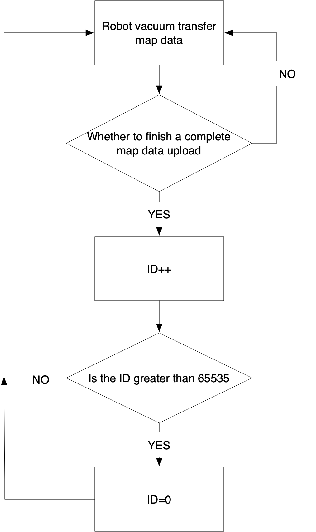
The module manages the map session ID. Before the MCU transmits a new map, it will request a map session ID from the module and include the allocated session ID in each session data transmission. The sub-map ID is incremented by 1 as a new sub-map is added, such as
0x01,0x02,0x03, and more. -
If you do not want the module to manage the session ID, implementing this command is not necessary.
The MCU sends the following command.
| Field | Length | Description |
|---|---|---|
| Header | 2 | 0x55aa |
| Version | 1 | 0x03 |
| Command | 1 | 0x34 |
| Data length | 2 | 0x0001 |
| Data | 1 | 0x06 (subcommand) |
| Checksum | 1 | Start from the header, add up all the bytes, and then divide the sum by 256 to get the remainder. |
For example, 55 aa 03 30 00 01 00 33
The module returns the following command.
| Field | Bytes | Description |
|---|---|---|
| Header | 2 | 0x55aa |
| Version | 1 | 0x00 |
| Command | 1 | 0x34 |
| Data length | 2 | 0x0004 |
| Data | 1 | 0x06 (subcommand) |
| 1 | Transmission result: 0x00: Success. 0x01: The map streaming service is not enabled. 0x02: Failed to get the session ID. |
|
| 2 | The map session ID. If the transmission fails, this data is invalid. | |
| Checksum | 1 | Start from the header, add up all the bytes, and then divide the sum by 256 to get the remainder. |
For example, 55 aa 00 34 00 04 06 00 00 00 3d
Test Wi-Fi functionality (connection)
-
The MCU sends the SSID and password of a router to the module. The module scans for this designated router.
-
The MCU determines whether the module is connected to the designated router based on the received network status. The test is considered failed if the MCU receives a failure or does not receive a result of a successful connection within 15 seconds.
-
The MCU can send the test command to enable the module to enter test mode again even after a successful test. However, if the MCU does not receive a result of a successful connection, it indicates the module is in the test progress. In this case, the module must be reset or restarted, and then the MCU sends the test command.
-
Make sure that the module has not paired. Otherwise, the test will fail.
-
Before the test, make sure that the MCU has responded to the heartbeat and product information query from the module and the initialization is completed.
-
The maximum length of the SSID and password is 32 bytes and 64 bytes respectively.
The MCU sends the following command.
| Field | Bytes | Description |
|---|---|---|
| Header | 2 | 0x55aa |
| Version | 1 | 0x03 |
| Command | 1 | 0x2C |
| Data length | 2 | n |
| Data | n | {"ssid":"xxx","password":"xxxxxxxx"}
|
| Checksum | 1 | Start from the header, add up all the bytes, and then divide the sum by 256 to get the remainder. |
For example, if the SSID and password is {"ssid":"xxx","password":"12345678"}, the MCU will send the following command.
55 aa 03 2c 00 24 7b 22 73 73 69 64 22 3a 22 78 78 78 22 2c 22 70 61 73 73 77 6f 72 64 22 3a 22 31 32 33 34 35 36 37 38 22 7d 2c
The module returns the following command.
| Field | Bytes | Description |
|---|---|---|
| Header | 2 | 0x55aa |
| Version | 1 | 0x00 |
| Command | 1 | 0x2C |
| Data length | 2 | 0x0001 |
| Data | 1 | The data length is one byte. Data[0]:
|
| Checksum | 1 | Start from the header, add up all the bytes, and then divide the sum by 256 to get the remainder. |
For example, 55 aa 00 2c 00 01 01 2d
Get module’s MAC address
The MCU sends the following command.
| Field | Bytes | Description |
|---|---|---|
| Header | 2 | 0x55aa |
| Version | 1 | 0x03 |
| Command | 1 | 0x2d |
| Data length | 2 | 0x0000 |
| Data | Data | None |
| Checksum | 1 | Start from the header, add up all the bytes, and then divide the sum by 256 to get the remainder. |
For example, 55 aa 03 2d 00 00 2f
The module returns the following command.
| Field | Bytes | Description |
|---|---|---|
| Header | 2 | 0x55aa |
| Version | 1 | 0x00 |
| Command | 1 | 0x2d |
| Data length | 2 | 0x0007 |
| Data | Data | Data[0]: indicates whether the MAC address is obtained successfully.
|
| Checksum | 1 | Start from the header, add up all the bytes, and then divide the sum by 256 to get the remainder. |
For example, if the MAC address is 508A0E3A2D9, the module returns the following command.
55 aa 00 2d 00 07 00 50 8a 06 e3 a2 d9 71
(Optional) IR status notification
| IR status | Description | Status value |
|---|---|---|
| Status 1 | IR code is being sent. | 0x00 |
| Status 2 | IR code is sent. | 0x01 |
| Status 3 | IR learning is in progress. | 0x02 |
| Status 4 | IR learning is completed. | 0x03 |
-
You can configure the IR feature on the Tuya Developer Platform or contact your project manager to enable this feature.
-
The short retention of IR code availability determines that serial data is sent directly without a resending mechanism.
-
You can configure the IR status indication as needed.
-
The IR TX and RX pins require two I/Os. If your module processes network events itself, do not use the IR pins for other configurations.
The module sends the following command.
| Field | Bytes | Description |
|---|---|---|
| Header | 2 | 0x55aa |
| Version | 1 | 0x00 |
| Command | 1 | 0x2e |
| Data length | 2 | 0x0001 |
| Data | Data | IR status indication:
|
| Checksum | 1 | Start from the header, add up all the bytes, and then divide the sum by 256 to get the remainder. |
For example, 55 aa 00 2e 00 01 00 2e
The MCU returns the following command.
| Field | Bytes | Description |
|---|---|---|
| Header | 2 | 0x55aa |
| Version | 1 | 0x03 |
| Command | 1 | 0x2e |
| Data length | 2 | 0x0000 |
| Data | Data | None |
| Checksum | 1 | Start from the header, add up all the bytes, and then divide the sum by 256 to get the remainder. |
For example, 55 aa 03 2e 00 00 30
(Optional) IR functionality test
-
Only the unpaired module can enter IR test mode.
-
The module enters IR learning status as it enters test mode.
-
Once the module enters test mode, it is in IR learning status and keeps transmitting the learned code until the module is paired or powered off.
The MCU sends the following command.
| Field | Bytes | Description |
|---|---|---|
| Header | 2 | 0x55aa |
| Version | 1 | 0x03 |
| Command | 1 | 0x2f |
| Data length | 2 | 0x0000 |
| Data | Data | None |
| Checksum | 1 | Start from the header, add up all the bytes, and then divide the sum by 256 to get the remainder. |
For example, 55 aa 03 2f 00 00 31
The module returns the following command.
| Field | Bytes | Description |
|---|---|---|
| Header | 2 | 0x55aa |
| Version | 1 | 0x00 |
| Command | 1 | 0x2f |
| Data length | 2 | 0x0001 |
| Data | Data |
|
| Checksum | 1 | Start from the header, add up all the bytes, and then divide the sum by 256 to get the remainder. |
For example, 55 aa 00 2f 00 01 00 2f
(Optional) RF functionality
-
To use RF functionality, you need to enable the RF remote control in the
abvfield through the command0x3700. -
When you use the RF code, multiple key values might be transmitted in a single operation. According to the maximum data length of the key value, the MCU serial buffer must be larger than 256 bytes. The MCU can use the
buffield in the command0x3700to notify the module of the MCU serial buffer size.
When multiple key values are to be transmitted in a single operation, the module can determine whether to transmit data in multiple packets based on the MCU serial buffer. The minimum packet size is a key value. For transmission of multiple key values, data of all key values is sent using one command by default. -
Since the MCU executes RF commands, the module is not intended to process status indication itself.
RF learning control
- The module sends commands to control the RF learning status of the MCU.
The module sends the following command.
| Field | Bytes | Description |
|---|---|---|
| Header | 2 | 0x55aa |
| Version | 1 | 0x00 |
| Command | 1 | 0x33 |
| Data length | 2 | 0x0002 |
| Data | 1 | Subcommand: 0x01 (RF learning command) |
| 1 | RF leaning status: 0x01: enter the RF learning status. 0x02: exit the RF learning status. |
|
| Checksum | 1 | Start from the header, add up all the bytes, and then divide the sum by 256 to get the remainder. |
For example, 55 aa 00 33 00 02 01 01 36
The MCU returns the following command.
| Field | Bytes | Description |
|---|---|---|
| Header | 2 | 0x55aa |
| Version | 1 | 0x03 |
| Command | 1 | 0x33 |
| Data length | 2 | 0x0003 |
| Data | 1 | Subcommand: 0x01 |
| 1 | RF leaning status: 0x01: enter the RF learning status. |
|
| 1 | Acknowledgement status: 0x00: Success. 0x02: Exit the RF learning status. 0x01: Failure. |
|
| Checksum | 1 | Start from the header, add up all the bytes, and then divide the sum by 256 to get the remainder. |
For example, 55 aa 03 33 00 03 01 01 00 3a
Send RF data
-
A piece of RF data can consist of multiple key values. If a piece of RF data exceeds the serial buffer capacity, key values can be transmitted in multiple packets.
-
RF data has a fixed encoding. The transmission time of each bit depends on the transmission rate. If a bit is
1, data is transmitted. If a bit is0, data is not transmitted and the high bit is transmitted first. -
The MCU only needs to parse the
Datafield without the fields of frequency and transmission rate.
The module sends the following command.
| Field | Length | Description |
|---|---|---|
| Header | 2 | 0x55aa |
| Version | 1 | 0x00 |
| Command | 1 | 0x33 |
| Data length | 2 | 0x07+n*(T+D+I+L+C) |
| Data | 1 | Subcommand: 0x02 |
| 1 | Type:
|
|
| 1 | The number of key values: n | |
| 1 | The serial number of the key value offset:
|
|
| 1 | Frequency:
|
|
| 2 | Transmission rate: such as 2,777 bps | |
| N | Data
|
|
| Checksum | 1 | Start from the header, add up all the bytes, and then divide the sum by 256 to get the remainder. |
For example, 55 aa 00 33 00 xx 02 01 00 ff 00 0a d9 00 00 00 00 00 00 xx xx xx xx xx xx xx
The MCU returns the following command.
| Field | Bytes | Description |
|---|---|---|
| Header | 2 | 0x55aa |
| Version | 1 | 0x03 |
| Command | 1 | 0x33 |
| Data length | 2 | 0x0002 |
| Data | 1 | Subcommand: 0x02 |
| 1 | Acknowledgement status:
|
|
| Checksum | 1 | Start from the header, add up all the bytes, and then divide the sum by 256 to get the remainder. |
For example, 55 aa 00 33 00 02 02 00 36
Report RF learning
The MCU sends the following command.
| Field | Length | Description |
|---|---|---|
| Header | 2 | 0x55aa |
| Version | 1 | 0x03 |
| Command | 1 | 0x33 |
| Data length | 2 | 0x0002+N |
| Data | 1 | Subcommand: 0x03 |
| 1 | Learning result:
|
|
| N | Data content: If learning failed, the MCU will not send this field. If learning succeeded, the MCU can send data in a custom format. |
|
| Checksum | 1 | Start from the header, add up all the bytes, and then divide the sum by 256 to get the remainder. |
For example, 55 aa 03 33 xx xx 03 00 xx xx xx xx xx xx
The module returns the following command.
| Field | Bytes | Description |
|---|---|---|
| Header | 2 | 0x55aa |
| Version | 1 | 0x00 |
| Command | 1 | 0x33 |
| Data length | 2 | 0x0002 |
| Data | 1 | Subcommand: 0x03 |
| 1 | Acknowledgement status:
|
|
| Checksum | 1 | Start from the header, add up all the bytes, and then divide the sum by 256 to get the remainder. |
For example, 55 aa 00 33 00 02 03 00 37
(Optional) File transfer service
- File transfer is not executed when MCU OTA updates are in progress. This command supports the transfer of large files and various file formats.
- To enable the file transfer feature, check whether the firmware supports this feature.
File download
File download process
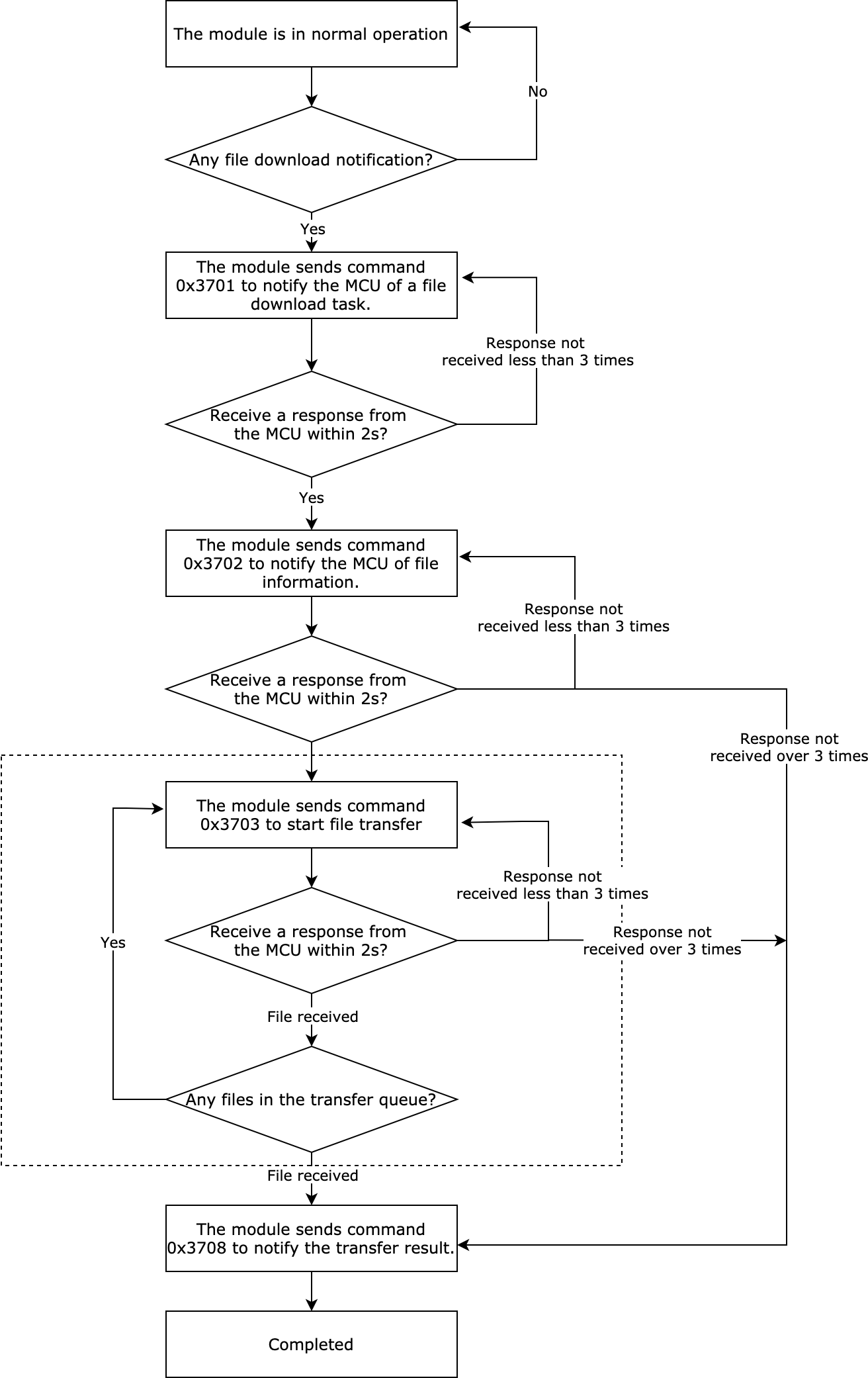
-
This diagram shows the download progress of a single file. Downloading multiple files work the same way, which repeats the process until all files are downloaded.
-
During file transfer, if the module exits the transfer process due to a time out, the whole process stops.
-
During file transfer, heartbeat interaction and DP data sending stop.
File download notification
-
The module sends this command to notify the MCU of a file download task. The MCU returns whether to execute the download task based on the current operation.
-
This command does not apply to download tasks for robot vacuum voice files.
The module sends the following command.
| Field | Bytes | Description |
|---|---|---|
| Header | 2 | 0x55aa |
| Version | 1 | 0x00 |
| Command | 1 | 0x37 |
| Data length | 2 | 0x0002 |
| Data | 1 | Subcommand: 0x01 |
| 1 | 0x01: fixed to 0x01 |
|
| Checksum | 1 | Start from the header, add up all the bytes, and then divide the sum by 256 to get the remainder. |
For example, 55 aa 00 37 00 02 01 01 3a
The MCU returns the following command.
| Field | Bytes | Description |
|---|---|---|
| Header | 2 | 0x55aa |
| Version | 1 | 0x03 |
| Command | 1 | 0x37 |
| Data length | 2 | 0x0003 |
| Data | 1 | Subcommand: 0x01 |
| 1 | The module returns whether to execute file download.
|
|
| 1 | If the MCU returns 0x00, this field indicates the file size in each packet. The available parameters are as follows.
0x01, this field indicates the download task is rejected. For more information about reasons, see Appendix 2. |
|
| Checksum | 1 | Start from the header, add up all the bytes, and then divide the sum by 256 to get the remainder. |
For example, 55 aa 00 37 00 03 01 00 07 41
File information sync
-
The module sends this command to notify the MCU of the information of the download file.
-
This command does not apply to download tasks for robot vacuum voice files.
The module sends the following command.
| Field | Bytes | Description |
|---|---|---|
| Header | 2 | 0x55aa |
| Version | 1 | 0x00 |
| Command | 1 | 0x37 |
| Data length | 2 | 0x0001+N |
| Data | 1 | Subcommand: 0x02 |
| N | num: the number of files in the download task. name: the file name. id: the serial number of the file. len: the file length. type: the file type. file_info: the custom data of each file. ext_info: the custom data, used to extend data. act: the specific actions performed in the download task. |
|
| Checksum | 1 | Start from the header, add up all the bytes, and then divide the sum by 256 to get the remainder. |
Field description
-
Name: the file name, which can be customized.
-
Id: the file ID.
-
Len: the file length.
-
Type: the file type, such as TXT and JPG. For more information about file formats, see Appendix 5.
-
File_info: the custom data of each file. You can use this field to add self-defined data. The module will transfer the raw data of this field to the MCU.
-
Ext_info: the custom data of the download file. You can use this field to add self-defined information for download operations. The module will transfer the raw data of this field to the MCU.
-
Act: the action performed in the download task, such as print and audio play. The following table lists the definition.
Name Print Text display Audio play Video play Store Type value 1 2 3 4 5
Note that if you do not specify a value for this field, the module will not transmit this field.
The MCU returns the following command.
| Field | Bytes | Description |
|---|---|---|
| Header | 2 | 0x55aa |
| Version | 1 | 0x03 |
| Command | 1 | 0x37 |
| Data length | 2 | 0x0002 |
| Data | 1 | Subcommand: 0x02 |
| 1 |
|
|
| Checksum | 1 | Start from the header, add up all the bytes, and then divide the sum by 256 to get the remainder. |
For example, 55 aa 03 37 00 02 02 00 3d
File transfer
-
The data format of the file transfer: packet offset (unsigned short) + packet data.
-
If the MCU receives a frame with a data length equal to 5 bytes and the packet offset is equal to or greater than the file size, the packet transmission ends.
The module sends the following command.
| Field | Bytes | Description |
|---|---|---|
| Header | 2 | 0x55aa |
| Version | 1 | 0x00 |
| Command | 1 | 0x37 |
| Data length | 2 | 0x02 + 0x0004 + packet length |
| Data | 1 | Subcommand: 0x03 |
| 1 | The serial number of the file in transfer. The first file is 1. The second one is 2, and so on. | |
| 4 | The packet offset. | |
| N | The packet content. | |
| Checksum | 1 | Start from the header, add up all the bytes, and then divide the sum by 256 to get the remainder. |
For example, if the serial number of the file is 1 and packet offset is 0, the module will send the following command.
55 aa 00 37 xx xx 03 01 00 00 00 00 00 xx xx xx xx xx
The MCU returns the following command.
| Field | Bytes | Description |
|---|---|---|
| Header | 2 | 0x55aa |
| Version | 1 | 0x03 |
| Command | 1 | 0x37 |
| Data length | 2 | 0x0002 |
| Data | 1 | Subcommand: 0x03 |
| 1 |
|
|
| Checksum | 1 | Start from the header, add up all the bytes, and then divide the sum by 256 to get the remainder. |
For example, 55 aa 03 37 00 02 03 00 3e
(Optional) Execution results
The MCU can use this command to send execution status to the module.
This command is optional. You can implement it if your product requires execution feedback. Data of act is also optional, depending on your product features.
Data of id corresponds to the id field (serial number of the file) of the command 0x3702.
The MCU sends the following command.
| Field | Bytes | Description |
|---|---|---|
| Header | 2 | 0x55aa |
| Version | 1 | 0x03 |
| Command | 1 | 0x37 |
| Data length | 2 | 0x01+l+L+2 |
| Data | 1 | Subcommand: 0x05 |
| 1 | The length of id. |
|
| L | The ID of a file, corresponding to the data of id field of the command 0x3702. |
|
| 1 | act:
|
|
| 1 | If act is 0x00, set this field to 0x00. If act is 0x01, set this field to the progress in percentage. For example, if the progress is 20%, set the field to the value 20. If act is 0x02, this field indicates the error code. For more information, see Appendix 2. |
|
| Checksum | 1 | Start from the header, add up all the bytes, and then divide the sum by 256 to get the remainder. |
For example, if a printer is printing a file of ID 10 and the task progress is at 20%, the MCU will send the following command.
55 aa 03 37 05 05 01 0a 01 14 63
The module returns the following command.
| Field | Bytes | Description |
|---|---|---|
| Header | 2 | 0x55aa |
| Version | 1 | 0x00 |
| Command | 1 | 0x37 |
| Data length | 2 | 0x0002 |
| Data | 1 | Subcommand: 0x05 |
| 1 |
|
|
| Checksum | 1 | Start from the header, add up all the bytes, and then divide the sum by 256 to get the remainder. |
For example, 55 aa 00 37 00 02 05 00 3d
File upload service
File upload process
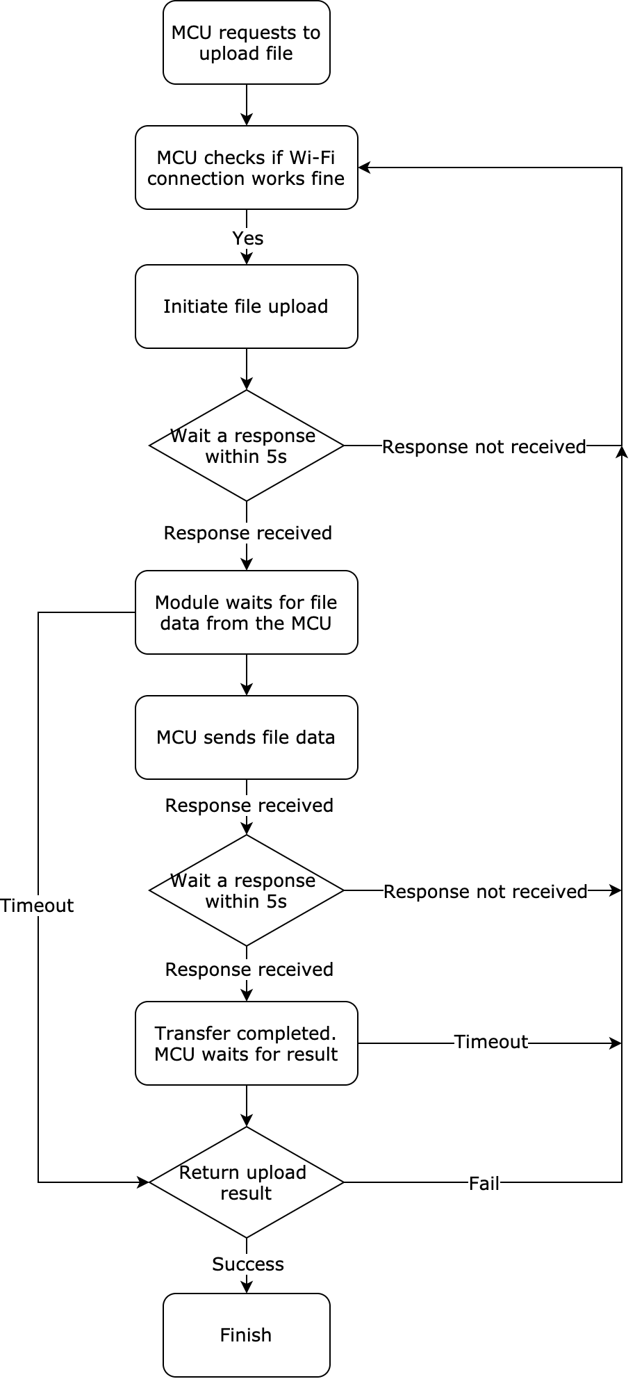
Initiate file upload
The MCU sends this command to the module to request uploading files.
The MCU sends the following data.
| Field | Length (byte) | Description |
|---|---|---|
| Header | 2 | 0x55aa |
| Version | 1 | 0x03 |
| Command | 1 | 0x37 |
| Data length | 2 | 0x0001+N |
| Data | 1 | Subcommand: 0x06 |
| N | { "num":n; the number of files in the download task. "files"[ { "name":"xx", the file name. "id":n, the serial number of the file. "len":n, the file length. "type": n, the file type. "file_info":"xx", the custom data of each file. }, { "name":"xx", the file name. "id":n, the serial number of the file. "len":n, the file length. "type": n, the file type. "file_info":"xx", the custom data of each file. }, … ] "ext_info":"xxxx" } |
|
| Checksum | 1 | Start from the header, add up all the bytes, and then divide the sum by 256 to get the remainder. |
The module returns the following data.
| Field | Length (byte) | Description |
|---|---|---|
| Header | 2 | 0x55aa |
| Version | 1 | 0x00 |
| Command | 1 | 0x37 |
| Data length | 2 | 0x0002 |
| Data | 1 | Subcommand: 0x06 |
| 1 | Ret: The result of command execution.
|
|
| Checksum | 1 | Start from the header, add up all the bytes, and then divide the sum by 256 to get the remainder. |
File upload
- Data format: packet offset (unsigned short) + payload.
- When the module receives a frame with a data length equal to 4 bytes and the packet offset is greater than or equal to the size of the update, the transfer is completed.
The MCU sends the following data.
| Field | Length (byte) | Description |
|---|---|---|
| Header | 2 | 0x55aa |
| Version | 1 | 0x03 |
| Command | 1 | 0x37 |
| Data length | 2 | 0x00020x0004 + packet length |
| Data | 1 | Sub-command: 0x07 |
| 2 | The ID of the file being transferred. | |
| 4 | File offset. | |
| N | The packet content. | |
| Checksum | 1 | Start from the header, add up all the bytes, and then divide the sum by 256 to get the remainder. |
The module sends the following data.
| Field | Length (byte) | Description |
|---|---|---|
| Header | 2 | 0x55aa |
| Version | 1 | 0x03 |
| Command | 1 | 0x37 |
| Data length | 2 | 0x0003 |
| Data | 1 | Subcommand: 0x07 |
| 1 |
|
|
| 1 |
|
|
| Checksum | 1 | Start from the header, add up all the bytes, and then divide the sum by 256 to get the remainder. |
The MCU proactively get or update file transfer status
- If the MCU proactively interrupts the file transfer, it can use this command to notify the module of the current transfer status.
The MCU sends the following command.
| Field | Bytes | Description |
|---|---|---|
| Header | 2 | 0x55aa |
| Version | 1 | 0x03 |
| Command | 1 | 0x37 |
| Data length | 2 | 0x0003 |
| Data | 1 | Subcommand: 0x04 |
| 1 |
|
|
| 1 |
|
|
| Checksum | 1 | Start from the header, add up all the bytes, and then divide the sum by 256 to get the remainder. |
For example, 55 aa 03 37 00 03 04 02 00 42
The module returns the following command.
| Field | Bytes | Description |
|---|---|---|
| Header | 2 | 0x55aa |
| Version | 1 | 0x00 |
| Command | 1 | 0x37 |
| Data length | 2 | 0x0003 |
| Data | 1 | Subcommand: 0x04 |
| 1 |
|
|
| 1 |
|
|
| Checksum | 1 | Start from the header, add up all the bytes, and then divide the sum by 256 to get the remainder. |
For example, 55 aa 00 37 00 03 04 02 00 3f
File transfer result
The module can use this command to notify the MCU of the result of file download or upload.
The module sends the following command.
| Field | Bytes | Description |
|---|---|---|
| Header | 2 | 0x55aa |
| Version | 1 | 0x00 |
| Command | 1 | 0x37 |
| Data length | 2 | 0x0004 |
| Data | 1 | Subcommand: 0x08 |
| 1 |
|
|
| 1 | Execution result.
|
|
| 1 | If the execution result is 0x00, 0x00 will be returned. If the execution result is 0x01, a failure reason will be returned. For more information, see Appendix 3. |
|
| Checksum | 1 | Start from the header, add up all the bytes, and then divide the sum by 256 to get the remainder. |
For example, 55 aa 00 37 00 04 08 01 00 00 43
The MCU returns the following command.
| Field | Bytes | Description |
|---|---|---|
| Header | 2 | 0x55aa |
| Version | 1 | 0x03 |
| Command | 1 | 0x37 |
| Data length | 2 | 0x0001 |
| Data | 1 | Subcommand: 0x08 |
| Checksum | 1 | Start from the header, add up all the bytes, and then divide the sum by 256 to get the remainder. |
For example, 55 aa 03 37 00 01 08 42
(Optional) Voice features
The protocols in this section only apply to the voice module VWXR2.
(Optional) Get voice status
The voice module will send the voice status to the MCU. Alternatively, the MCU can proactively query the voice status.
The MCU sends the following command.
| Field | Bytes | Description |
|---|---|---|
| Header | 2 | 0x55aa |
| Version | 1 | 0x03 |
| Command | 1 | 0x60 |
| Data length | 2 | 0x0000 |
| Data | 0 | None |
| Checksum | 1 | Start from the header, add up all the bytes, and then divide the sum by 256 to get the remainder. |
For example, 55 aa 03 60 00 00 62
The module returns the following command.
| Field | Bytes | Description |
|---|---|---|
| Header | 2 | 0x55aa |
| Version | 1 | 0x00 |
| Command | 1 | 0x60 |
| Data length | 2 | 0x0001 |
| Data | 1 | Voice status code.
|
| Checksum | 1 | Start from the header, add up all the bytes, and then divide the sum by 256 to get the remainder. |
For example, 55 aa 00 60 00 01 00 60
(Optional) Mute the mic
The MCU can use this command to mute the mic or query the mic status.
The MCU sends the following command.
| Field | Bytes | Description |
|---|---|---|
| Header | 2 | 0x55aa |
| Version | 1 | 0x03 |
| Command | 1 | 0x61 |
| Data length | 2 | 0x0001 |
| Data | 1 |
|
| Checksum | 1 | Start from the header, add up all the bytes, and then divide the sum by 256 to get the remainder. |
For example, 55 aa 03 61 00 01 00 64
The module returns the following command.
| Field | Bytes | Description |
|---|---|---|
| Header | 2 | 0x55aa |
| Version | 1 | 0x00 |
| Command | 1 | 0x61 |
| Data length | 2 | 0x0001 |
| Data | 1 |
|
| Checksum | 1 | Start from the header, add up all the bytes, and then divide the sum by 256 to get the remainder. |
For example, 55 aa 00 61 00 01 00 61
(Optional) Adjust the speaker volume
The MCU can use this command to adjust the speaker volume or query the current volume.
The MCU sends the following command.
| Field | Bytes | Description |
|---|---|---|
| Header | 2 | 0x55aa |
| Version | 1 | 0x03 |
| Command | 1 | 0x62 |
| Data length | 2 | 0x0001 |
| Data | 1 |
|
| Checksum | 1 | Start from the header, add up all the bytes, and then divide the sum by 256 to get the remainder. |
For example, 55 aa 03 62 00 01 03 68
The module returns the following command.
| Field | Bytes | Description |
|---|---|---|
| Header | 2 | 0x55aa |
| Version | 1 | 0x00 |
| Command | 1 | 0x62 |
| Data length | 2 | 0x0001 |
| Data | 1 | Volume: 0 to 10. |
| Checksum | 1 | Start from the header, add up all the bytes, and then divide the sum by 256 to get the remainder. |
For example, 55 aa 00 62 00 01 03 65
(Optional) Test audio functionality
Record voices and while play the recording. Use acoustic equipment to compare the input and output audio signals.
The MCU sends the following command.
| Field | Bytes | Description |
|---|---|---|
| Header | 2 | 0x55aa |
| Version | 1 | 0x03 |
| Command | 1 | 0x63 |
| Data length | 2 | 0x0001 |
| Data | 1 |
|
| Checksum | 1 | Start from the header, add up all the bytes, and then divide the sum by 256 to get the remainder. |
For example, 55 aa 03 63 00 01 02 68
The module returns the following command.
| Field | Bytes | Description |
|---|---|---|
| Header | 2 | 0x55aa |
| Version | 1 | 0x00 |
| Command | 1 | 0x63 |
| Data length | 2 | 0x0001 |
| Data | 1 |
|
| Checksum | 1 | Start from the header, add up all the bytes, and then divide the sum by 256 to get the remainder. |
For example, 55 aa 00 63 00 01 02 65
(Optional) Test waking up voice assistant
After the voice module enters test mode, the wake word must be delivered within 10 seconds. If the module is not woken up within 10 seconds, it returns a failure result.
The MCU sends the following command.
| Field | Bytes | Description |
|---|---|---|
| Header | 2 | 0x55aa |
| Version | 1 | 0x03 |
| Command | 1 | 0x64 |
| Data length | 2 | 0x0000 |
| Data | 0 | None |
| Checksum | 1 | Start from the header, add up all the bytes, and then divide the sum by 256 to get the remainder. |
For example, 55 aa 03 64 00 00 66
The module returns the following command.
| Field | Bytes | Description |
|---|---|---|
| Header | 2 | 0x55aa |
| Version | 1 | 0x00 |
| Command | 1 | 0x64 |
| Data length | 2 | 0x0001 |
| Data | 0 |
|
| Checksum | 1 | Start from the header, add up all the bytes, and then divide the sum by 256 to get the remainder. |
For example, 55 aa 00 64 00 01 01 65
Extended features
You can implement the following extended features for your voice modules.
- Notifications and settings of play/pause, Bluetooth on/off, local alarm, and grouped voice controls.
- Play/pause: applies to songs, jokes, and more.
- Bluetooth on/off: turns on or off Bluetooth of a Bluetooth speaker.
- Local alarm: sync alarms set by the voice control to the mobile app.
- Grouped voice controls: notifications of voice control commands. For example, play next or previous media.
The MCU sends the following command.
| Field | Bytes | Description |
|---|---|---|
| Header | 2 | 0x55aa |
| Version | 1 | 0x03 |
| Command | 1 | 0x65 |
| Data length | 2 | N |
| Data | 1 | Subcommand: 0x00 |
| Data: { "play":true, "bt_play":true ,"ctrl_group":"xxxx"} |
|
|
| Checksum | 1 | Start from the header, add up all the bytes, and then divide the sum by 256 to get the remainder. |
For example, if the data is {"play":true,"bt_play":true,"ctrl_group":"next"}, the MCU will send the following command.
55 aa 03 65 00 31 00 7b 22 70 6c 61 79 22 3a 74 72 75 65 2c 22 62 74 5f 70 6c 61 79 22 3a 74 72 75 65 2c 22 63 74 72 6c 5f 67 72 6f 75 70 22 3a 22 6e 65 78 74 22 7d c7
The module returns the following command.
| Field | Bytes | Description |
|---|---|---|
| Header | 2 | 0x55aa |
| Version | 1 | 0x00 |
| Command | 1 | 0x65 |
| Data length | 2 | 0x0002 |
| Data | 1 | Subcommand: 0x00 |
| 1 |
|
|
| Checksum | 1 | Start from the header, add up all the bytes, and then divide the sum by 256 to get the remainder. |
For example, 55 aa 00 65 00 02 00 00 66
Status notification
The module sends the following command.
| Field | Bytes | Description |
|---|---|---|
| Header | 2 | 0x55aa |
| Version | 1 | 0x00 |
| Command | 1 | 0x65 |
| Data length | 2 | 1+N |
| Data | 1 | Subcommand: 0x01 |
| Data: { "play":true, "bt_play":true," alarm":"xxxx","ctrl_group":"xxxx"} |
|
|
| Checksum | 1 | Start from the header, add up all the bytes, and then divide the sum by 256 to get the remainder. |
For example, if the data is {"play":true,"bt_play":true,"ctrl_group":"next","alarm":"xxx"}, the module sends the following command.
55 aa 00 65 00 3f 01 7b 22 70 6c 61 79 22 3a 74 72 75 65 2c 22 62 74 5f 70 6c 61 79 22 3a 74 72 75 65 2c 22 63 74 72 6c 5f 67 72 6f 75 70 22 3a 22 6e 65 78 74 22 2c 22 61 6c 61 72 6d 22 3a 22 78 78 78 22 7d 36
The MCU returns the following command.
| Field | Bytes | Description |
|---|---|---|
| Header | 2 | 0x55aa |
| Version | 1 | 0x03 |
| Command | 1 | 0x65 |
| Data length | 2 | 2 |
| Data | 1 | Subcommand: 0x01 |
| 1 |
|
|
| Checksum | 1 | Start from the header, add up all the bytes, and then divide the sum by 256 to get the remainder. |
For example, 55 aa 03 65 00 02 01 00 6a
Wake up the module
-
The MCU can send this command to wake up the module.
-
This command only applies to modules that run on Linux and are interfaced using the general protocols.
The MCU sends the following command.
| Field | Bytes | Description |
|---|---|---|
| Header | 2 | 0x55aa |
| Version | 1 | 0x03 |
| Command | 1 | 0x65 |
| Data length | 2 | 0x01 |
| Data | 1 | Subcommand: 0x02 |
| Checksum | 1 | Start from the header, add up all the bytes, and then divide the sum by 256 to get the remainder. |
For example, 55 aa 03 65 00 01 02 6a
The module returns the following command.
| Field | Bytes | Description |
|---|---|---|
| Header | 2 | 0x55aa |
| Version | 1 | 0x00 |
| Command | 1 | 0x65 |
| Data length | 2 | 0x02 |
| Data | 1 | Subcommand: 0x02 |
| 1 |
|
|
| Checksum | 1 | Start from the header, add up all the bytes, and then divide the sum by 256 to get the remainder. |
For example, 55 aa 00 65 00 02 02 00 68
Notification of turning on/off automatic speech recognition (ASR)
After this feature is enabled, ASR processed texts will be transmitted through the command 0x6504.
The MCU sends the following command.
| Field | Bytes | Description |
|---|---|---|
| Header | 2 | 0x55aa |
| Version | 1 | 0x03 |
| Command | 1 | 0x65 |
| Data length | 2 | 0x02 |
| Data | 1 | Subcommand: 0x03 |
| 1 |
|
|
| Checksum | 1 | Start from the header, add up all the bytes, and then divide the sum by 256 to get the remainder. |
For example, 55 aa 03 65 00 02 03 00 6c
The module returns the following command.
| Field | Bytes | Description |
|---|---|---|
| Header | 2 | 0x55aa |
| Version | 1 | 0x00 |
| Command | 1 | 0x65 |
| Data length | 2 | 0x02 |
| Data | 1 | Subcommand: 0x03 |
| 1 |
|
|
| Checksum | 1 | Start from the header, add up all the bytes, and then divide the sum by 256 to get the remainder. |
For example, 55 aa 00 65 00 02 03 00 69
Notification of ASR processing
The module sends the following command.
| Field | Bytes | Description |
|---|---|---|
| Header | 2 | 0x55aa |
| Version | 1 | 0x03 |
| Command | 1 | 0x65 |
| Data length | 2 | 0xXX |
| Data | 1 | Subcommand: 0x04 |
| 1 |
|
|
| Checksum | 1 | Start from the header, add up all the bytes, and then divide the sum by 256 to get the remainder. |
For example, if the data is {"text":"xx","speaker":"human", "id":1171}, the module will send the following command.
55 aa 03 65 00 2b 04 7b 22 74 65 78 74 22 3a 22 78 78 22 2c 22 73 70 65 61 6b 65 72 22 3a 22 68 75 6d 61 6e 22 2c 20 22 69 64 22 3a 31 31 37 31 7d 69
The MCU returns the following command.
| Field | Bytes | Description |
|---|---|---|
| Header | 2 | 0x55aa |
| Version | 1 | 0x00 |
| Command | 1 | 0x65 |
| Data length | 2 | 0x01 |
| Data | 1 | Subcommand: 0x04 |
| Checksum | 1 | Start from the header, add up all the bytes, and then divide the sum by 256 to get the remainder. |
For example, 55 aa 00 65 00 01 04 69
Query the current playing media
- The MCU can use this command to query the current playing media.
- The returned content is represented in UTF-8 format and transmitted in hex.
The MCU sends the following command.
| Field | Bytes | Description |
|---|---|---|
| Header | 2 | 0x55aa |
| Version | 1 | 0x03 |
| Command | 1 | 0x65 |
| Data length | 2 | 0x01 |
| Data | 1 | Subcommand: 0x05 |
| Checksum | 1 | Start from the header, add up all the bytes, and then divide the sum by 256 to get the remainder. |
For example, 55 aa 03 65 00 01 05 6d
The module returns the following command.
| Field | Bytes | Description |
|---|---|---|
| Header | 2 | 0x55aa |
| Version | 1 | 0x00 |
| Command | 1 | 0x65 |
| Data length | 2 | 0x0002+N |
| Data | 1 | Subcommand: 0x05 |
| 1 | Data[0]:
|
|
| N | If the result is 0x01, this part is empty. If the result is 0x00, the data is artist and trackTitle. |
|
| Checksum | 1 | Start from the header, add up all the bytes, and then divide the sum by 256 to get the remainder. |
For example, if the data is {"artist":"Beethoven", "trackTitle":"Serenade in D major, Op.8"}, the module sends the following command.
55 aa 00 65 00 34 05 00 7b 22 61 72 74 69 73 74 22 3a 22 e8 96 9b e4 b9 8b e8 b0 a6 22 2c 22 74 72 61 63 6b 54 69 74 6c 65 22 3a 22 e5 8a a8 e7 89 a9 e4 b8 96 e7 95 8c 22 7d dc
Report status to the module
The MCU sends the following command.
| Field | Bytes | Description |
|---|---|---|
| Header | 2 | 0x55aa |
| Version | 1 | 0x03 |
| Command | 1 | 0x65 |
| Data length | 2 | 0x02 |
| Data | 1 | Subcommand: 0x06 |
|
||
| Checksum | 1 | Start from the header, add up all the bytes, and then divide the sum by 256 to get the remainder. |
For example, 55 aa 03 65 00 02 06 00 6f
The module returns the following command.
| Field | Bytes | Description |
|---|---|---|
| Header | 2 | 0x55aa |
| Version | 1 | 0x00 |
| Command | 1 | 0x65 |
| Data length | 2 | 0x02 |
| Data | 1 | Subcommand: 0x06 |
| 1 |
|
|
| Checksum | 1 | Start from the header, add up all the bytes, and then divide the sum by 256 to get the remainder. |
For example, 55 aa 00 65 00 02 06 00 6c
Report recording (auto)
The MCU can send this command to trigger voice recording. The module will pick up voices and automatically end the recording. The recording can be up to 10 seconds long in one go.
The MCU sends the following command.
| Field | Bytes | Description |
|---|---|---|
| Header | 2 | 0x55aa |
| Version | 1 | 0x03 |
| Command | 1 | 0x65 |
| Data length | 2 | 0x02 |
| Data | 1 | Sub-command: 0x07 |
| 0x01: start recording. | ||
| Checksum | 1 | Start from the header, add up all the bytes, and then divide the sum by 256 to get the remainder. |
For example, 55 aa 03 65 00 02 07 01 71
The module returns the following command.
| Field | Bytes | Description |
|---|---|---|
| Header | 2 | 0x55aa |
| Version | 1 | 0x00 |
| Command | 1 | 0x65 |
| Data length | 2 | 0x02 |
| Data | 1 | Sub-command: 0x07 |
| 1 |
|
|
| Checksum | 1 | Start from the header, add up all the bytes, and then divide the sum by 256 to get the remainder. |
For example, 55 aa 00 65 00 02 07 00 6d
Report recording (manual)
The MCU can send this command to trigger voice recording but the recording must be ended manually. The recording can be up to 10 seconds long in one go.
The MCU sends the following command.
| Field | Bytes | Description |
|---|---|---|
| Header | 2 | 0x55aa |
| Version | 1 | 0x03 |
| Command | 1 | 0x65 |
| Data length | 2 | 0x02 |
| Data | 1 | Subcommand: 0x08 |
| 1 |
|
|
| Checksum | 1 | Start from the header, add up all the bytes, and then divide the sum by 256 to get the remainder. |
For example, 55 aa 03 65 00 02 08 00 71
The module returns the following command.
| Field | Bytes | Description |
|---|---|---|
| Header | 2 | 0x55aa |
| Version | 1 | 0x00 |
| Command | 1 | 0x65 |
| Data length | 2 | 0x02 |
| Data | 1 | Subcommand: 0x08 |
| 1 |
|
|
| Checksum | 1 | Start from the header, add up all the bytes, and then divide the sum by 256 to get the remainder. |
For example, 55 aa 00 65 00 02 08 00 6e
Turn on/off alarms
After this feature is enabled, alarm data will be transmitted through the command 0x650A.
The MCU sends the following command.
| Field | Bytes | Description |
|---|---|---|
| Header | 2 | 0x55aa |
| Version | 1 | 0x03 |
| Command | 1 | 0x65 |
| Data length | 2 | 0x02 |
| Data | 1 | Subcommand: 0x09 |
| 1 |
|
|
| Checksum | 1 | Start from the header, add up all the bytes, and then divide the sum by 256 to get the remainder. |
For example, 55 aa 03 65 00 02 09 01 73
The module returns the following command.
| Field | Bytes | Description |
|---|---|---|
| Header | 2 | 0x55aa |
| Version | 1 | 0x00 |
| Command | 1 | 0x65 |
| Data length | 2 | 0x02 |
| Data | 1 | Subcommand: 0x09 |
| 1 |
|
|
| Checksum | 1 | Start from the header, add up all the bytes, and then divide the sum by 256 to get the remainder. |
For example, 55 aa 00 65 00 02 09 00 6f
Send alarms
The module sends the following command.
| Field | Bytes | Description |
|---|---|---|
| Header | 2 | 0x55aa |
| Version | 1 | 0x00 |
| Command | 1 | 0x65 |
| Data length | 2 | 0xXX |
| Data | 1 | Subcommand: 0x0A |
| Data[0]: the number of alarms. Data[1]: the operation type. 0: poll. 1: add. 2: delete. 3: update.
0: online ringtone. Other values: local ringtone. Data[15] to Data[35]: a ringtone description, used to match a song. |
||
| Checksum | 1 | Start from the header, add up all the bytes, and then divide the sum by 256 to get the remainder. |
For example, if a one-time alarm with ID 1 is scheduled to go off at 17:32 on August 23, 2021, the module will send the following command.
55 aa 00 65 00 24 0a 01 01 00 00 00 00 00 01 15 08 17 11 20 00 00 00 00 00 00 00 00 00 00 00 00 00 00 00 00 00 00 00 00 00 00 00 fa
The MCU returns the following command.
| Field | Bytes | Description |
|---|---|---|
| Header | 2 | 0x55aa |
| Version | 1 | 0x03 |
| Command | 1 | 0x65 |
| Data length | 2 | 0x01 |
| Data | 1 | Subcommand: 0x0A |
| Checksum | 1 | Start from the header, add up all the bytes, and then divide the sum by 256 to get the remainder. |
For example, 55 aa 03 65 00 01 0a 72
Query alarm list
The MCU sends the following command.
| Field | Bytes | Description |
|---|---|---|
| Header | 2 | 0x55aa |
| Version | 1 | 0x03 |
| Command | 1 | 0x65 |
| Data length | 2 | 0x01 |
| Data | 1 | Subcommand: 0x0B |
| Checksum | 1 | Start from the header, add up all the bytes, and then divide the sum by 256 to get the remainder. |
For example, 55 aa 03 65 00 01 0b 73
The module returns an alarm list through the command 0x650A.
Turn on/off local alarms
The MCU sends the following command.
| Field | Bytes | Description |
|---|---|---|
| Header | 2 | 0x55aa |
| Version | 1 | 0x03 |
| Command | 1 | 0x65 |
| Data length | 2 | 0x02 |
| Data | 1 | Subcommand: 0x0C |
|
||
| Checksum | 1 | Start from the header, add up all the bytes, and then divide the sum by 256 to get the remainder. |
For example, 55 aa 03 65 00 02 0c 00 75
The module returns the following command.
| Field | Bytes | Description |
|---|---|---|
| Header | 2 | 0x55aa |
| Version | 1 | 0x00 |
| Command | 1 | 0x65 |
| Data length | 2 | 0x02 |
| Data | 1 | Subcommand: 0x0C |
| 1 |
|
|
| Checksum | 1 | Start from the header, add up all the bytes, and then divide the sum by 256 to get the remainder. |
For example, 55 aa 00 65 00 02 0c 00 72
Manage alarms
The MCU sends the following command.
| Field | Bytes | Description |
|---|---|---|
| Header | 2 | 0x55aa |
| Version | 1 | 0x03 |
| Command | 1 | 0x65 |
| Data length | 2 | 0xXX |
| Data | 1 | Subcommand: 0x0D |
|
||
| Data is in JSON format. | ||
| Checksum | 1 | Start from the header, add up all the bytes, and then divide the sum by 256 to get the remainder. |
For example, if the data is {"date":"20210326","time":"17:05","loops":"0000000","timeZone":"+08:00","bell":0}, the MCU will send the following command.
55 aa 03 65 00 53 0d 01 7b 22 64 61 74 65 22 3a 22 32 30 32 31 30 33 32 36 22 2c 22 74 69 6d 65 22 3a 22 31 37 3a 30 35 22 2c 22 6c 6f 6f 70 73 22 3a 22 30 30 30 30 30 30 30 22 2c 22 74 69 6d 65 5a 6f 6e 65 22 3a 22 2b 30 38 3a 30 30 22 2c 22 62 65 6c 6c 22 3a 30 7d 9e
The module returns the following command.
| Field | Bytes | Description |
|---|---|---|
| Header | 2 | 0x55aa |
| Version | 1 | 0x00 |
| Command | 1 | 0x65 |
| Data length | 2 | 0x09 |
| Data | 1 | Subcommand: 0x0D |
| 1 |
|
|
| 1 |
|
|
| 6 | timerId of an operation. |
|
| Checksum | 1 | Start from the header, add up all the bytes, and then divide the sum by 256 to get the remainder. |
For example, 55 aa 00 65 00 09 0d 01 00 00 00 00 00 00 0a 85
Manage alarms in JSON format
Set an alarm
| Name | Type | Description | Optional |
|---|---|---|---|
| time | String | Set a time for an alarm, such as 08:30. | N |
| loops | String | Repeat an alarm. Sunday through Saturday, specify the day or days of the week when the alarm should recur. 1 means an alarm recurs on that day every week. For example, 0100001 represents an alarm that should go off on Monday and Saturday every week. |
N |
| date | String | Set a date for an alarm. For a recurring alarm, this field defaults to 00000000. To schedule a one-time alarm, specify a date when an alarm should go off, such as 20181126. |
N |
| timeZone | String | The timezone, such as +08:00. |
N |
| bell | Integer | The alarm ringtone, represented by a positive integer and defaulting to 1. 0: online ringtone. Other values: local ringtone. |
Y |
| bellDesc | String | The ringtone description, used to match a song. | Y |
- One-time alarm:
{ "date": "20181126", "time": "20:30", "loops": "0000000", "timeZone": "+08:00", "bell":1 } - Recurring alarm:
{ "date": "00000000", "time": "08:00", "loops": "0111110", "timeZone": "+08:00", "bell":1 }
Edit an alarm
| Name | Type | Description | Optional |
|---|---|---|---|
| time | String | Set a time for an alarm, such as 08:30. | N |
| loops | String | Repeat an alarm. Sunday through Saturday, specify the day or days of the week when the alarm should recur. 1 means an alarm recurs on that day every week. For example, 0100001 represents an alarm that should go off on Monday and Saturday every week. |
N |
| date | String | Set a date for an alarm. For a recurring alarm, this field defaults to 00000000. To schedule a one-time alarm, specify a date when an alarm should go off, such as 20181126. |
N |
| timerId | Long | Alarm ID | N |
| timeZone | String | The timezone, such as +08:00. |
N |
| bell | Integer | The alarm ringtone, represented by a positive integer and defaulting to 1. 0: online ringtone. Other values: local ringtone. |
Y |
| bellDesc | String | The ringtone description, used to match a song. | Y |
- One-time alarm:
{ "timerId": 10164075, "date": "20210322", "time": "14:30", "loops": "0000000", "timeZone": "+08:00", "bell":1 } - Recurring alarm:
{ "timerId": 10164075, "date": "20210322", "time": "14:30", "loops": "0111110", "timeZone": "+08:00", "bell":1 }
Delete an alarm
Request parameters
| Name | Type | Description | Optional |
|---|---|---|---|
| timerId | Long | Alarm ID | N |
Sample request
{"timerId": 1002}
Dismiss an alarm
Request parameters
| Name | Type | Description | Optional |
|---|---|---|---|
| timerId | Long | Alarm ID | N |
Sample request
{"timerId": 1002}
Enable an alarm
Request parameters
| Name | Type | Description | Optional |
|---|---|---|---|
| timerId | Long | Alarm ID | N |
Sample request
{"timerId": 1002}
Query the number of reminders
The MCU sends the following command.
| Field | Bytes | Description |
|---|---|---|
| Header | 2 | 0x55aa |
| Version | 1 | 0x03 |
| Command | 1 | 0x65 |
| Data length | 2 | 0x01 |
| Data | 1 | Subcommand: 0x0E |
| Checksum | 1 | Start from the header, add up all the bytes, and then divide the sum by 256 to get the remainder. |
For example, 55 aa 03 65 00 01 0e 76
The module returns the following command.
| Field | Bytes | Description |
|---|---|---|
| Header | 2 | 0x55aa |
| Version | 1 | 0x00 |
| Command | 1 | 0x65 |
| Data length | 2 | 0x02 |
| Data | 1 | Subcommand: 0x0E |
| 1 | The number of reminders: 0 to 30. | |
| Checksum | 1 | Start from the header, add up all the bytes, and then divide the sum by 256 to get the remainder. |
For example, 55 aa 00 65 00 02 0e 02 76
Send alarm data
The MCU sends the following command.
| Field | Bytes | Description |
|---|---|---|
| Header | 2 | 0x55aa |
| Version | 1 | 0x03 |
| Command | 1 | 0x65 |
| Data length | 2 | 0x0001+N |
| Data | 1 | Subcommand: 0x0F |
| N | text: The texts or text commands stored on the device. type:
|
|
| Checksum | 1 | Start from the header, add up all the bytes, and then divide the sum by 256 to get the remainder. |
For example, if the data is {"text":"Play Beethoven","type":"music","target":"alert"}, the MCU will send the following command.
55 aa 03 65 00 41 0f 7b 22 74 65 78 74 22 3a 22 e6 92 ad e6 94 be e6 9e 97 e4 bf 8a e6 9d b0 e7 9a 84 e6 ad 8c 22 2c 22 74 79 70 65 22 3a 22 6d 75 73 69 63 22 2c 22 74 61 73 67 65 74 22 3a 22 61 6c 65 72 74 22 7d 91
The module returns the following command.
| Field | Bytes | Description |
|---|---|---|
| Header | 2 | 0x55aa |
| Version | 1 | 0x00 |
| Command | 1 | 0x65 |
| Data length | 2 | 0x0002 |
| Data | 1 | Subcommand: 0x0F |
| 1 |
|
|
| Checksum | 1 | Start from the header, add up all the bytes, and then divide the sum by 256 to get the remainder. |
For example, 55 aa 00 65 00 02 0f 00 75
Extended services
Enable time service notification
-
This feature enables the module to notify the MCU of whether it has synced time with the server after startup.
-
The MCU sends a command to enable the required time service. The module syncs time with the server after startup and then returns the time data the MCU requests.
-
If the time service has already been enabled, the module will reject the repeated enablement request unless it is restarted. In this case, the MCU should use the common command of getting time data.
-
When you use Get system time in GMT and Get local time, the module will not immediately sync time with the server after it is connected to the server. However, during this period, the MCU still keeps requesting time data. This notification feature allows the MCU to wait for the message from the module without keeping asking.
The MCU sends the following command.
| Field | Length | Description |
|---|---|---|
| Header | 2 | 0x55aa |
| Version | 1 | 0x03 |
| Command | 1 | 0x34 |
| Data length | 2 | 0x0002 |
| Data | 1 | 0x01 (sub-command) |
| 1 |
|
|
| Checksum | 1 | Start from the header, add up all the bytes, and then divide the sum by 256 to get the remainder. |
For example, 55 aa 03 34 00 02 01 01 3a
The module returns the following command.
| Field | Bytes | Description |
|---|---|---|
| Header | 2 | 0x55aa |
| Version | 1 | 0x00 |
| Command | 1 | 0x34 |
| Data length | 2 | 0x0002 |
| Data | 1 | 0x01 (sub-command) |
| 1 |
|
|
| Checksum | 1 | Start from the header, add up all the bytes, and then divide the sum by 256 to get the remainder. |
For example, 55 aa 00 34 00 02 01 00 36
Time service notification
-
The module sends the time data according to the time service the MCU requests.
-
After the module is restarted, the time service is disabled. The MCU must send the command to enable the time service notification.
The module sends the following command.
| Field | Length | Description |
|---|---|---|
| Header | 2 | 0x55aa |
| Version | 1 | 0x00 |
| Command | 1 | 0x34 |
| Data length | 2 | 0x0009 |
| Data | 1 | 0x02 (sub-command) |
| 1 | ||
| 7 | The data length is 7 bytes.
|
|
| Checksum | 1 | Start from the header, add up all the bytes, and then divide the sum by 256 to get the remainder. |
For example, if the local time is Monday at 18:35:28 on August 23, 2021, the module sends the following command.
55 aa 00 34 00 09 02 01 15 08 17 12 23 1c 01 c5
The MCU returns the following command.
| Field | Bytes | Description |
|---|---|---|
| Header | 2 | 0x55aa |
| Version | 1 | 0x03 |
| Command | 1 | 0x34 |
| Data length | 2 | 0x0001 |
| Data | 1 | 0x02 (sub-command) |
| Checksum | 1 | Start from the header, add up all the bytes, and then divide the sum by 256 to get the remainder. |
For example, 55 aa 03 34 00 01 02 39
(Optional) Enable reset status notification
A device can be reset with operations on the hardware or the mobile app. However, the MCU will not be notified of related status. This feature will enable the module to proactively send its status to the MCU.
The MCU sends the following command.
| Field | Length | Description |
|---|---|---|
| Header | 2 | 0x55aa |
| Version | 1 | 0x03 |
| Command | 1 | 0x34 |
| Data length | 2 | 0x0001 |
| Data | 1 | 0x04 (sub-command) |
| Checksum | 1 | Start from the header, add up all the bytes, and then divide the sum by 256 to get the remainder. |
For example, 55 aa 03 34 00 01 04 3b
The module returns the following command.
| Field | Bytes | Description |
|---|---|---|
| Header | 2 | 0x55aa |
| Version | 1 | 0x00 |
| Command | 1 | 0x34 |
| Data length | 2 | 0x0002 |
| Data | 1 | 0x04 (sub-command) |
| 1 | ||
| Checksum | 1 | Start from the header, add up all the bytes, and then divide the sum by 256 to get the remainder. |
For example, 55 aa 00 34 00 02 04 00 39
(Optional) The reset status
| Reset status | Description | Status value |
|---|---|---|
| Status 1 | Reset by hardware operation | 0x00 |
| Status 2 | Reset performed on the mobile app | 0x01 |
| Status 3 | Factory reset performed on the mobile app | 0x02 |
The module will resend the packet two times at a one second interval if it receives no response.
The module sends the following command.
| Field | Bytes | Description |
|---|---|---|
| Header | 2 | 0x55aa |
| Version | 1 | 0x00 |
| Command | 1 | 0x34 |
| Data length | 2 | 0x0002 |
| Data | 1 | 0x05 (sub-command) |
| 1 | ||
| Checksum | 1 | Start from the header, add up all the bytes, and then divide the sum by 256 to get the remainder. |
For example, 55 aa 00 34 00 02 05 00 3a
The MCU returns the following command.
| Field | Bytes | Description |
|---|---|---|
| Header | 2 | 0x55aa |
| Version | 1 | 0x03 |
| Command | 1 | 0x34 |
| Data length | 2 | 0x0001 |
| Data | 1 | 0x05 (sub-command) |
| Checksum | 1 | Start from the header, add up all the bytes, and then divide the sum by 256 to get the remainder. |
For example, 55 aa 03 34 00 01 05 3c
Get information about Wi-Fi module
-
The running data of the Wi-Fi module is required for some products. This field is used to get the required information.
-
The MCU can send a specified code to the module to get the required information. If the MCU requires multiple types of information, the codes must be sent in order.
-
If the MCU requires all the information available, it can use the code
0xff. -
This command only supports getting the SSID of an AP.
-
If the SSID of an AP is the default
smartlife, this command only returnssmartlife. The actual SSID issmartlife_xxxx.xxxxrepresents the last four digits of the MAC address.- The data format of this field is in JSON string and the data length varies depending on the information type.
- The length of data that the MCU sends to the module must be at least 2 bytes, namely the sub-command plus a 1-byte data code. If the data length is incorrect, the module will return a failure.
- The data codes have a one-to-one relationship with the information types. Make sure you use the correct data code and do not use the reserved code.
| Name | Encoding |
|---|---|
| All the information available | 0xff |
| SSID of an AP | 0x01 |
| Country code | 0x02 |
| Serial number (SN) of the module | 0x03 |
| Frustration-Free Setup (FFS) authorization history | 0x04 |
| … | … |
-
For more information about the returned fields, see Appendix 4.
- The common Wi-Fi modules do not support getting their SNs.
- If a module does not have FFS authorization history, the
ffsfield will return0. - If a module has FFS authorization history, the
ffsfield will return1, coupled with the SN value to assist in verification.
The MCU sends the following command.
| Field | Length | Description |
|---|---|---|
| Header | 2 | 0x55aa |
| Version | 1 | 0x03 |
| Command | 1 | 0x34 |
| Data length | 2 | 0x01+0x01+…N |
| Data | 1 | Sub-command: 0x07 |
| Data(1) |
|
|
| Data(2) |
|
|
| Data(N) |
|
|
| Checksum | 1 | Start from the header, add up all the bytes, and then divide the sum by 256 to get the remainder. |
For example, 55 aa 03 34 00 02 07 01 40
The module returns the following command.
| Field | Bytes | Description |
|---|---|---|
| Header | 2 | 0x55aa |
| Version | 1 | 0x00 |
| Command | 1 | 0x34 |
| Data length | 2 | 0x02+N |
| Data | 1 | 0x07 (sub-command) |
| 1 |
|
|
| Data (N) |
|
|
| Checksum | 1 | Start from the header, add up all the bytes, and then divide the sum by 256 to get the remainder. |
For example, if the data is {"ap":"PlusStyle"}, the module returns the following command.
55 aa 00 34 00 14 07 00 7b 22 61 70 22 3a 22 50 6c 75 73 53 74 79 6c 65 22 7d 8e
(Optional) Bluetooth features
Bluetooth functional test
-
The module scans for the designated Bluetooth beacon
ty_mdevand returns the result and signal strength in percentage. -
To prevent quality defects, it is recommended that the distance between the router and the device under test should be about 5 meters. If the signal strength is greater than or equal to 60%, the device is acceptable. The specific testing conditions depend on your production line and environment.
The MCU sends the following command.
| Field | Length | Description |
|---|---|---|
| Header | 2 | 0x55aa |
| Version | 1 | 0x03 |
| Command | 1 | 0x35 |
| Data length | 2 | 0x0001 |
| Data | 1 | 0x01 (sub-command) |
| Checksum | 1 | Start from the header, add up all the bytes, and then divide the sum by 256 to get the remainder. |
For example, 55 aa 03 35 00 01 01 39
The module returns the following command.
| Field | Bytes | Description |
|---|---|---|
| Header | 2 | 0x55aa |
| Version | 1 | 0x00 |
| Command | 1 | 0x35 |
| Data length | 2 | 0x0003 |
| Data | 1 | 0x01 (sub-command) |
| 2 | The data length is 2 bytes. Data[0]: 0x00 indicates failure, and 0x01 indicates success.
|
|
| Checksum | 1 | Start from the header, add up all the bytes, and then divide the sum by 256 to get the remainder. |
For example, 55 aa 00 35 00 03 01 01 14 4d
Report Bluetooth connection status
| Bluetooth connection status | Description | Status value |
|---|---|---|
| Status 1 | Unbound and not connected | 0x00 |
| Status 2 | Unbound and connected | 0x01 |
| Status 3 | Bound and not connected | 0x02 |
| Status 4 | Bound and connected | 0x03 |
| Status 5 | Unknown status | 0x04 |
- The module enters status 1 and status 2 when pairing over Bluetooth.
- The LED activity in the module self-processing mode.
- Status 1: Blink quickly.
- Status 2 or Status 3: Steady off.
- Status 4: Steady on.
- Status 5: Blink slowly.
When the module detects that the MCU is restarted or reconnected, it will proactively send the current Bluetooth connection status to the MCU.
- When the Bluetooth connection status changes, the module will proactively send the current status to the MCU.
- If you choose the module self-processing mode, implementing this protocol for your MCU is not necessary.
To enable reporting Bluetooth connection status, the MCU should enable Bit 0 in abv field when it sends 0x3700 command to the module after power on.
The Bluetooth connection when power on defaults to unknown status.
The module sends the following data.
| Field | Length (byte) | Description |
|---|---|---|
| Header | 2 | 0x55aa |
| Version | 1 | 0x00 |
| Command | 1 | 0x35 |
| Data length | 2 | 0x0002 |
| Data | Subcommand | 0x04 |
| 1 | Indicate the work status of Bluetooth.
|
|
| Checksum | 1 | Start from the header, add up all the bytes, and then divide the sum by 256 to get the remainder. |
Example: 55 aa 00 35 00 02 04 03 3d
The MCU returns the following data.
| Field | Length (byte) | Description |
|---|---|---|
| Header | 2 | 0x55aa |
| Version | 1 | 0x03 |
| Command | 1 | 0x35 |
| Data length | 2 | 0x0001 |
| Data | Subcommand | 0x04 |
| Checksum | 1 | Start from the header, add up all the bytes, and then divide the sum by 256 to get the remainder. |
Example: 55 aa 00 35 00 01 04 39
Request Bluetooth connection status
| Bluetooth connection status | Description | Status value |
|---|---|---|
| Status 1 | Unbound and not connected | 0x00 |
| Status 2 | Unbound and connected | 0x01 |
| Status 3 | Bound and not connected | 0x02 |
| Status 4 | Bound and connected | 0x03 |
| Status 5 | Unknown status | 0x04 |
The status definition must be consistent with that defined in Report Bluetooth connection status.
The MCU sends the following data.
| Field | Length (byte) | Description |
|---|---|---|
| Header | 2 | 0x55aa |
| Version | 1 | 0x03 |
| Command | 1 | 0x35 |
| Data length | 2 | 0x0001 |
| Data | Data | 05 |
| Checksum | 1 | Start from the header, add up all the bytes, and then divide the sum by 256 to get the remainder. |
Example: 55 aa 03 35 00 01 05 3D
The module returns the following data.
| Field | Length (byte) | Description |
|---|---|---|
| Header | 2 | 0x55aa |
| Version | 1 | 0x00 |
| Command | 1 | 0x35 |
| Data length | 2 | 0x0002 |
| Data | Subcommand | 0x05 |
| Data | Indicate the work status of Bluetooth.
|
|
| Checksum | 1 | Start from the header, add up all the bytes, and then divide the sum by 256 to get the remainder. |
Example: 55 aa 03 35 00 02 05 00 3E
Data notification for Bluetooth/Beacon remote control
- Bluetooth remote control service must be enabled to use this feature.
- The module enters pairing mode after the
0x02command interaction. The pairing mode is only active for 30 seconds. - Up to five devices can be paired with the Bluetooth remote control. Otherwise, pairing will fail.
The module sends the following data.
| Field | Length (byte) | Description |
|---|---|---|
| Header | 2 | 0x55aa |
| Version | 1 | 0x00 |
| Command | 1 | 0x35 |
| Data length | 2 | 0x0007 |
| Data | 1 | Subcommand: 0x06 |
| N |
|
|
| Checksum | 1 | Start from the header, add up all the bytes, and then divide the sum by 256 to get the remainder. |
Example: 55 aa 03 35 00 02 05 00 3E
The MCU returns the following data.
| Field | Length | Description |
|---|---|---|
| Header | 2 | 0x55aa |
| Version | 1 | 0x03 |
| Command | 1 | 0x35 |
| Data length | 2 | 0x0001 |
| Data | 1 | 0x06 (subcommand) |
| Checksum | 1 | Start from the header, add up all the bytes, and then divide the sum by 256 to get the remainder. |
Example: 55 aa 03 35 00 02 05 00 3E
Control commands
Command (1 byte) |
Generic command (1 byte) |
Command data (4 bytes) Padded with 0 if needed |
|
|---|---|---|---|
Category ID |
|||
Generic: 0xFF Individual category Lighting product: 0x01 Socket/power strip: 0x02 Curtain switch: 0x03 Drying rack: 0x04 Fan: 0x05 Bathroom heater: 0x06 Air conditioner: 0x07 Garage door opener: 0x08 Water valve: 0x09 Disinfector: 0x0A Thermostat plug: 0x0B Dimmer switch: 0x0C Scene socket: 0x0D Switch: 0x0E Smart curtain switch module: 0x0F |
Send key values: 0x01 |
Byte 1: Button behavior (0 – Single press. 1 – Double press. 2 – Long press. 3 – Press and hold. 4 – Press and release) Byte 2: The key value. |
|
Switch: 0x04 |
Byte 1: 0 – Turn off. 1 – Turn on. 2 – Pause. Byte 2: The number of gangs. 0 represents the main control. |
||
Add favorites: 0x05 |
Byte 1: 1 – Favorite a state. 2 – Go to a specified favorite. Byte 2: The ID of a favorite, ranging from 0 to 3. |
||
Countdown timer: 0x06 |
Bytes 1 to 2: The countdown time, in seconds and big-endian format. 0 indicates canceling the countdown timer. Byte 3: The action to run when the countdown timer is done. (Reserved byte) |
||
One-click group query: 0x07 |
The sub-device advertises the information about the added group. |
||
Light on/off: 0x08 |
Byte 1: 0 – Turn off. 1 – Turn on. Byte 2: 0 – The main switch. 1 – White light switch. 2 – Colored light switch. |
||
Brightness adjustment: 0x09 |
Byte 1: 0 – Brightness value. 1 – Brightness up. 2 – Brightness down. Byte 2: 0 – Brightness of the current mode. 1 – Brightness of white light. Byte 3: When Byte 1 is 0, this byte indicates brightness percentage (1 to 100%). When Byte 1 is 1 or 2, this byte indicates the step value of brightness (1 to 100%). |
||
Stepless brightness adjustment: 0x0A |
Byte 1: 0 – Start incrementing. 1 – Start decrementing. 2 – Stop adjustment. Byte 2: 0 – Brightness of the current mode. 1 – Brightness of white light. Byte 3: Rate (adjustment percentage per second) Byte 4: The target value. |
||
Color temperature adjustment: 0x0B |
Byte 1: 0 – Color temperature value. 1 – Color temperature up. 2 – Color temperature down. Byte 2: When Byte 1 is 0, this byte indicates color temperature percentage (0 to 100%). When Byte 1 is 1 or 2, this byte indicates the step value of color temperature (0 to 100%). |
||
Stepless color temperature adjustment: 0x0C |
Byte 1: 0 – Start incrementing. 1 – Start decrementing. 2 – Stop adjustment. Byte 2: Rate (adjustment percentage per second) Byte 3: The target value. |
||
Color adjustment: 0x0D |
Byte 1: 0 – Relative transition. 1 – The specified color. 2 – Start cycling adjustment. 3 – Stop cycling adjustment. Byte 2: The ID of the specified color when Byte 1 is 1. |
||
Hue adjustment: 0x0E |
Byte 1: 0 – Hue value. 1 – Hue up. 2 – Hue down. Byte 2: When Byte 1 is 0, this byte indicates hue percentage (0 to 100%). When Byte 1 is 1 or 2, this byte indicates the step value of hue (0 to 100%). |
||
Stepless hue adjustment:0x0F |
Byte 1: 0 – Start incrementing. 1 – Start decrementing. 2 – Stop adjustment. Byte 2: Rate (adjustment percentage per second) Byte 3: The target value. |
||
Saturation adjustment: 0x10 |
Byte 1: 0 – Saturation value. 1 – Saturation up. 2 – Saturation down. Byte 2: When Byte 1 is 0, this byte indicates saturation percentage (0 to 100%). When Byte 1 is 1 or 2, this byte indicates the step value of saturation (0 to 100%). |
||
Stepless saturation adjustment: 0x11 |
Byte 1: 0 – Start incrementing. 1 – Start decrementing. 2 – Stop adjustment. Byte 2: Rate (adjustment percentage per second) Byte 3: The target value. |
||
Value adjustment: 0x12 |
Byte 1: 0 – Value. 1 – Value up. 2 – Value down. Byte 2: When Byte 1 is 0, this byte indicates value percentage (1 to 100%). When Byte 1 is 1 or 2, this byte indicates the step value of value (1 to 100%). |
||
Stepless value adjustment: 0x13 |
Byte 1: 0 – Start incrementing. 1 – Start decrementing. 2 – Stop adjustment. Byte 2: Rate (adjustment percentage per second) Byte 3: The target value. |
||
HSV (hue, saturation, value) adjustment: 0x14 |
Byte 1: Hue percentage (0 to 100%) Byte 2: Saturation (0 to 100%) Byte 3: Value percentage (1 to 100%) |
||
Scene adjustment: 0x15 |
Byte 1: 0 – Relative transition. 1 – The specified scene. 2 – Start cycling adjustment. 3 – Stop cycling adjustment. Byte 2: The ID of the specified scene when Byte 1 is 1. |
||
Lighting mode selection: 0x16 |
Byte 1: 1 – Night light mode. |
||
Motor rotation adjustment: 0x20 |
Byte 1: 0 – Clockwise rotation. 1 – Counterclockwise rotation. 2 – Pause. Byte 2: Travel percentage (0 to 100%). 0 – Continuous rotation. Byte 3: The number of channels. 0 represents the total channel. |
||
Motor travel setting : 0x21 |
Byte 1: 0 – The start position. 1 – The fine-tuning position. 2 – The end position. Byte 2: 0 – The up limit. 1 – The down limit. 2 – The intermediate limit. Byte 3: The number of channels. 0 represents the total channel. |
||
Movement speed adjustment: 0x22 |
Byte 1: 0 – Speed. 1 – Step increment. 2 – Step decrement. Byte 2: The specified speed or step value of speed. Byte 3: The number of channels. 0 represents the total channel. |
||
Stepless movement speed adjustment: 0x23 |
Byte 1: 0 – Start incrementing. 1 – Start decrementing. 2 – Stop adjustment. Byte 2: Rate (adjustment percentage per second) Byte 3: The target value. Byte 4: The number of channels. 0 represents the total channel. |
||
Temperature adjustment: 0x24 |
Byte 1: 0 – The temperature value. 1 – Temperature up. 2 – Temperature down. Bytes 2 to 3: When Byte 1 is 0, this byte indicates the specified temperature. When Byte 1 is 1 or 2, this byte indicates the step value of temperature. The 2-byte temperature value is stored in big-endian. The most significant bit represents the sign (minus or plus) and the rest of the bits represent the number. The number multiplied by 0.1°C is the actual temperature. |
||
Stepless temperature adjustment: 0x25 |
Byte 1: 0 – Start incrementing. 1 – Start decrementing. 2 – Stop adjustment. Byte 2: Rate (adjustment percentage per second) Bytes 3 to 4: The target value of temperature, which is calculated same as above. |
||
Humidity adjustment: 0x26 |
Byte 1: 0 – Humidity value. 1 – Humidity up. 2 – Humidity down. Byte 2: The specified humidity. |
||
Stepless humidity adjustment: 0x27 |
Byte 1: 0 – Start incrementing. 1 – Start decrementing. 2 – Stop adjustment. Byte 2: Rate (adjustment percentage per second) Byte 3: The target value. |
||
Custom command |
|||
Custom category (1 byte) |
Custom command (1 byte) |
Parameter (3 bytes) |
|
Lights: 0xFF |
RGBY (red, green, blue, yellow) adjustment:0x01 |
Byte 1: 0 – Change color to red. 1 – Change color to green. 2 – Change color to blue. 3 – Change color to yellow. |
|
Fan: 0xFE |
Fan mode: 0x01 |
Byte 1: 0 – Manual adjustment. 1 – Natural wind. 2: Sleep wind. |
|
Bathroom heater: 0xFD |
Bathroom heater mode: 0x01 |
Byte 1: 0 – Heating. 1 – Ventilation. 2 – Drying. 3 – Fan. |
|
Air conditioner: 0xFC |
Sleep: 0x01 |
Byte 1: 0 – Off. 1 – On. |
|
Report and send data of extended DPs
This feature only applies to voice services.
Enable the extended DP service
-
This service extends the source of data sending to LAN, WAN, and Bluetooth.
-
This service conflicts with Send commands.
The MCU sends the following command.
| Field | Bytes | Description |
|---|---|---|
| Header | 2 | 0x55aa |
| Version | 1 | 0x03 |
| Command | 1 | 0x36 |
| Data length | 2 | 0x0002 |
| Data | 1 | Subcommand: 0x01 |
| 1 |
|
|
| Checksum | 1 | Start from the header, add up all the bytes, and then divide the sum by 256 to get the remainder. |
For example, 55 aa 03 36 00 02 01 01 3c
The module returns the following command.
| Field | Bytes | Description |
|---|---|---|
| Header | 2 | 0x55aa |
| Version | 1 | 0x00 |
| Command | 1 | 0x36 |
| Data length | 2 | 0x0002 |
| Data | 1 | Subcommand: 0x01 |
| 1 |
|
|
| Checksum | 1 | Start from the header, add up all the bytes, and then divide the sum by 256 to get the remainder. |
For example, 55 aa 00 36 00 02 01 00 38
Send commands of extended DPs
-
For more information, seeData units.
-
A command can contain data units of multiple DPs.
-
The module sends control commands and the MCU reports DP status, which occurs asynchronously.
-
The source of extended DP data sending must be set manually, which conflicts with the Send commands and Report status.
The module sends the following command.
| Field | Bytes | Description |
|---|---|---|
| Header | 2 | 0x55aa |
| Version | 1 | 0x00 |
| Command | 1 | 0x36 |
| Data length | 2 | Depends on the type and number of data units (N+2). |
| Data | 1 | Subcommand: 0x02 |
| 1 | The source of data sending:
|
|
| N | Data units | |
| Checksum | 1 | Start from the header, add up all the bytes, and then divide the sum by 256 to get the remainder. |
For example, in LAN, if DP 3 of a boolean type is used for on/off control, and 1 means to turn on the device, the module will send the following command.
For example, 55 aa 00 36 0007 02 01 03 01 0001 01 45
Report status of extended DPs
-
This feature only applies to offline voice modules.
-
For more information, see Data unit.
-
The MCU asynchronously reports DP status, which can be triggered by three mechanisms.
-
After the MCU executes the command of extended DPs from the module, it reports the changed status of extended DPs to the module.
-
When the MCU proactively detects status changes of DPs, it reports the changed DP status to the module.
-
When the MCU receives DP status queries, it sends the status of all DPs to the module.
-
The MCU can report data units of multiple DPs.
The MCU sends the following command.
| Field | Bytes | Description |
|---|---|---|
| Header | 2 | 0x55aa |
| Version | 1 | 0x03 |
| Command | 1 | 0x36 |
| Data length | 2 | Depends on the type and number of data units (N+3). |
| Data | 1 | Subcommand: 0x03 |
| 1 |
|
|
| 1 | When the MCU proactively reports DP status or responds to status queries, it responds to the data source requested by Send commands of extended DPs with 0x00.
|
|
| N | Data units | |
| Checksum | 1 | Start from the header, add up all the bytes, and then divide the sum by 256 to get the remainder. |
For example, in WAN, if the DP 5 of value type indicates the current humidity of 30%, the MCU sends the following command to the module.
For example, 55 aa 03 36 000b 03 02 02 05 02 0004 0000001e 73
(Optional) Smart fan features
This section only applies to specific fan categories.
Fan functional test
For example, a fan with a step of 20 and a hold-time of five seconds. The module can adjust the motor to 0%, 20%, 40%, 60%, 80%, and 100% in sequence at an interval of five seconds.
The MCU sends the following command.
| Field | Length | Description |
|---|---|---|
| Header | 2 | 0x55aa |
| Version | 1 | 0x03 |
| Command | 1 | 0x72 |
| Data length | 2 | 0x03 |
| Data | 1 | 0x01 (sub-command) |
| 1 | 0x0a: step of fan speed, ranging from 1 to 99. | |
| 1 | 0x05: the speed level hold-time, ranging from 1 to 100 seconds. | |
| Checksum | 1 | Start from the header, add up all the bytes, and then divide the sum by 256 to get the remainder. |
For example, 55 aa 03 72 00 03 01 0a 05 87
The module returns the following command.
| Field | Bytes | Description |
|---|---|---|
| Header | 2 | 0x55aa |
| Version | 1 | 0x00 |
| Command | 1 | 0x72 |
| Data length | 2 | 0x02 |
| Data | 1 | 0x01 (sub-command) |
| 1 |
|
|
| Checksum | 1 | Start from the header, add up all the bytes, and then divide the sum by 256 to get the remainder. |
For example, 55 aa 00 72 00 02 01 00 74
Set duty cycle
If the duty cycle is set to 70%, PWM1 outputs 70%, and PWM2 outputs 0%. If zero-crossing is detected, PWM1 outputs 0% and PWM2 outputs 70%.
The MCU sends the following command.
| Field | Length | Description |
|---|---|---|
| Header | 2 | 0x55aa |
| Version | 1 | 0x03 |
| Command | 1 | 0x72 |
| Data length | 2 | 0x02 |
| Data | 1 | 0x02 (sub-command) |
| 1 | 0x0a: ranging from 0% to 100%. | |
| Checksum | 1 | Start from the header, add up all the bytes, and then divide the sum by 256 to get the remainder. |
For example, 55 aa 03 72 00 02 02 0a 82
The module returns the following command.
| Field | Bytes | Description |
|---|---|---|
| Header | 2 | 0x55aa |
| Version | 1 | 0x00 |
| Command | 1 | 0x72 |
| Data length | 2 | 0x02 |
| Data | 1 | 0x02 (sub-command) |
| 1 |
|
|
| Checksum | 1 | Start from the header, add up all the bytes, and then divide the sum by 256 to get the remainder. |
For example, 55 aa 00 72 00 02 02 00 75
Appendix
This appendix only provides the defined contents. Do not use any undefined content.
Appendix 1: Module information
| Name | Description | Options | Obtain | Set |
|---|---|---|---|---|
| cc | Country code | 0: applies to Chinese mainland, Korea, Singapore, Australia, Japan (1-13), and others. 1: applies to the United States, Taiwan (China), and Canada. 2: applies to Japan (1-14) 3: applies to Europe |
Supported | Not supported |
| ap | Access point (AP) | String | Supported | Not supported |
| sn | Serial number (SN) of the module | The SN written to the module. | Not supported | Not supported |
| ffs | Indicates whether a module has FFS authorization information. | 0: A module does not have FFS authorization information. 1: A module has FFS authorization information. |
Supported | Not supported |
Appendix 2: File download exceptions
| Description | Status value |
|---|---|
| Device is shut down. | 0x00 |
| File transfer times out. | 0x01 |
| Battery level is low. | 0x02 |
| Device is overheating. | 0x03 |
| File is large. | 0x04 |
| Memory is not enough. | 0x05 |
| Operation anomaly occurs. For example, out of paper, paper jam, and cover open. |
0x06 |
Appendix 3: File transfer status
| Status | Description | Status value |
|---|---|---|
| Status 1 | No file transfer task. | 0x00 |
| Status 2 | File transfer is starting. | 0x01 |
| Status 3 | File transfer is in progress. | 0x02 |
| Status 4 | File transfer/download is completed. | 0x03 |
| Status 5 | File upload to the server succeeded. | 0x04 |
| Status 6 | File transfer with the MCU times out. | 0x05 |
| Status 7 | Failed to get the URL for file upload. | 0x06 |
| Status 8 | Failed to upload the file to the server. | 0x07 |
| Status 9 | Failed to get the file from the server. | 0x08 |
| Status 10 | The MCU fails to respond to file transfer. | 0x09 |
Appendix 4: OTA MCU firmware update
| Status | Description | Status value |
|---|---|---|
| Status 1 | Start update. | 0x00 |
| Status 2 | Update is in progress. | 0x01 |
| Status 3 | Update is completed. | 0x02 |
| Status 4 | Update failed. | 0x03 |
Appendix 5: File type
| Description | Value |
|---|---|
| TXT | 1 |
| DOC | 2 |
| 3 | |
| EXCEL | 4 |
| PNG | 5 |
| JPG | 6 |
| BMP | 7 |
| TIF | 8 |
| GIF | 9 |
| PCX | 10 |
| TGA | 11 |
| Exif | 12 |
| FPX | 13 |
| SVG | 14 |
| PSD | 15 |
| CDR | 16 |
| PCD | 17 |
| DXF | 18 |
| UFO | 19 |
| EPS | 20 |
| AI | 21 |
| Raw | 22 |
| WMF | 23 |
| WebP | 24 |
| AVIF | 25 |
| WAV | 26 |
| FLAC | 27 |
| APE | 28 |
| ALAC | 29 |
| WavPack (WV) | 30 |
| MP3 | 31 |
| AAC | 32 |
| Ogg Vorbis | 33 |
| Opus | 34 |
| MP4 | 35 |
Version history
| Version | Description | Date | Note |
|---|---|---|---|
| 1.2.5 | Modified | June 16, 2022 | 1. Added file download feature. 2. Added the protocol for Bluetooth/Beacon remote control. 3. Added the protocol for Bluetooth connection status notification. |
| 1.2.4 | Modified | July 1, 2021 | 1. Added support for multiple types of MCU firmware. 2. Added RF protocols. 3. Added support for getting Wi-Fi module information. 4. Added IR status indicator. 5. Updated voice module feature extension. 6. Added features of Bluetooth remote controls. 7. Added features of fans. |
| 1.2.3 | Modified | May 21, 2020 | 1. Added fields of IR feature and low-power mode enablement in the production info packet. 2. Added commands of proactively weather service requests. 3. Added command of notification of module reset. 4. Modified the description of module working mode. |
| 1.2.2 | Modified | April 11, 2020 | Add features of voice module VWXR2, including play/pause, Bluetooth on/off, local alarm, and group control. |
| 1.2.1 | Modified | April 9, 2020 | 1. Added Wi-Fi functional test. 2. Added Wi-Fi remote control feature. |
| 1.2.0 | Modified | March 31, 2020 | Added features to adapt to CI baseline. Added fields of network status and production information. |
| 1.1.9 | Modified | March 26, 2020 | 1. Updated voice service protocols. 2. Add extension features for modules. 3. Added production test for Wi-Fi and Bluetooth LE combo module. |
| 1.1.8 | Modified | February 18, 2020 | 1. Added volume setting for voice module VWXR2. 2. Added production test for audio and wake-up. |
| 1.1.7 | Modified | November 19, 2019 | 1. Added map data streaming for multiple maps. 2. Added channels for third-party file download. 3. Updated protocol description. |
| 1.1.6 | Modified | August 28, 2019 | Added IR features. |
| 1.1.5 | Modified | August 24, 2019 | 1. Added interface to get the MAC address of the module. 2. Updated description of requesting weather data. |
| 1.1.4 | Modified | June 17, 2019 | 1. Added performance test for Wi-Fi connection modes. 2. Updated streaming service. |
| 1.1.3 | Modified | April 15, 2019 | 1. Updated the description of commands. 2. Added features of robot vacuum. |
| 1.1.2 | Modified | December 17, 2018 | 1. Added pairing via serial port. 2. Added commands for the MCU to get the Wi-Fi network status. |
| 1.1.1 | Modified | August 10, 2018 | Updated the returns from the MCU to respond to the firmware update. (legacy version is compatible) |
| 1.1.0 | Modified | March 29, 2018 | Added the feature of turning off heartbeats. |
| 1.0.9 | Modified | January 19, 2018 | 1. Added synchronous reporting, enabling the module to return the report result on each data reporting task. 2. Added the feature to getting Wi-Fi signal strength, in dB. |
| 1.0.8 | Modified | May 12, 2017 | 1. Added the interface to enable weather service. 2. Added the interface to send the weather data to the MCU. 3. Modified the heartbeat interval to 15 seconds. |
| 1.0.7 | Modified | February 16, 2017 | 1. Added pairing mode setting, with an extended interface for product information query. 2. Updated the command to query MCU version number to 0x03. |
| 1.0.6 | Modified | November 10, 2016 | 1. Added Wi-Fi working status. 2. Updated the command to query MCU version number to 0x02. |
| 1.0.5 | Modified | June 7, 2016 | 1. Deleted update query command. 2. Delete the command used to notify the MCU to enter test mode. 3. Modified the protocol of starting firmware update, support for files over 64 KB in size. |
| 1.0.4 | Modified | May 12, 2016 | 1. Added the command to get the local time. 2. Added Wi-Fi functional test. 3. Added the command to get the module memory. |
| 1.0.3 | Modified | November 14, 2015 | 1. Added the command for the MCU to get the time data. 2. Added the command for the MCU to get the time zone. 3. Added the feature to enter test mode. |
| 1.0.2 | Modified | October 17, 2015 | 1. Added the feature of MCU restart detection in the heartbeat mechanism. 2. Modified the interval of heartbeat detection to 10 seconds. 3. Modified the proactive Wi-Fi status reporting to sending Wi-Fi status to the MCU. |
| 1.0.1 | Modified | October 13, 2015 | 1. Modified product ID query to module information query. 2. Added returning version number. |
| 1.0.0 | Create | October 10, 2015 | The first release. |
Is this page helpful?
YesFeedbackIs this page helpful?
YesFeedback


