Serial Communication Protocol
This topic describes the serial communication protocol for data exchange between Tuya’s Zigbee module (hereafter referred to as the module) and the MCU. The MCU manages the business logic and communicates with a Zigbee module via UART to enable a wireless connection. The module features:
-
Zigbee network management: Includes device pairing, network leaving, and local groups and scenes.
-
Zigbee gateway communication: The device connects to a gateway to exchange data with the cloud, supporting only the Tuya DP protocol.
-
Zigbee device communication: Enables communication between sub-devices, supporting the Tuya DP protocol and parts of the Zigbee 3.0 standard protocol.
-
MCU OTA: The MCU can receive firmware updates through the Zigbee module for OTA updates.
The serial protocol is continuously improved and updated, including adding new commands and optimizing command interactions. This protocol aims for forward compatibility, but it cannot guarantee compatibility with some legacy or non-long-term support firmware.
This topic covers protocols for both standard power and low power Zigbee modules. Support for protocols and timings may vary by the chip platform or firmware version. The applicable protocols depend on the module you are using. If you are unsure, consult the Tuya team. The latest version of the standard firmware is recommended.
Hardware connection
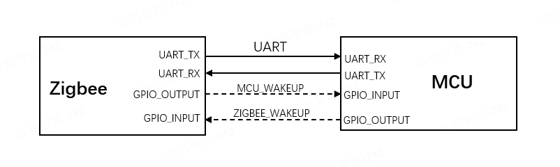
The following figure shows the connection between the Zigbee module and the MCU.
- For standard power devices, connect the UART TX and UART RX pins.
- For low power devices, the two wake-up pins are also required to enable the Zigbee module and MCU to wake each other up to receive serial data.
Serial communication
- Baud: 9600/115200 bps
- Data bit: 8
- Parity check: none
- Stop bit: 1
- Data flow control: none
- Supply voltage: Tuya’s Zigbee module and the MCU are supplied by 3.3V DC.
The table below lists the UART and wake-up pins for various Zigbee module models. Pin definitions may vary by firmware.
| Module model | Module TX | Module RX | Wake up MCU | Wake up module |
|---|---|---|---|---|
| ZS3L | PA5 | PA6 | PC1 | PA3 |
| ZS13S | PA5 | PA6 | PC1 | PA3 |
| ZSU | PA5 | PA6 | PC1 | PA3 |
| ZSC | PA5 | PA6 | PA0 | PA3 |
| TYZS3 | PA0 | PA1 | PF5 | PA2 |
| TYZS5 | PA0 | PA1 | PA4 | PA3 |
| ZTU | PB1/PC2 | PB7/PC3 | PB4 | PB5/PD2 |
| ZT3L | PB1/PC2 | PB7/PC3 | PB4 | PB5/PD2 |
| ZT5 | PB1/PC2 | PB7/PC3 | PB4 | PB5/PD2 |
| ZT2S | PB1/PC2 | PB7/PC3 | PB4 | PB5/PD2 |
Low power wake-up
Low power devices cannot receive serial data in sleep mode. Before the Zigbee module and MCU exchange serial data, they wake each other up. After the transmission is complete, they notify each other to enter sleep mode.
Wake up by voltage levels
Pull down the wake-up pin to activate the other party, and then send the serial data. Once the transmission is complete, pull up the wake-up pin. When there is no data transmission, the wake-up pin should stay at a high level, as shown below.
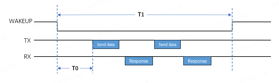
T0 is the waiting time after pulling down the wake-up pin for the other party to exit sleep mode, while T1 is the total time taken to wake the other party up.
- The recommended T0 for the MCU to wake up the Zigbee module is 1 to 10 milliseconds. For the ZT series modules, T0 is at least 10 milliseconds.
- The total wake-up time T1 for the MCU to wake up the Zigbee module must not exceed two minutes. Otherwise, the Zigbee module will reset and restart.
- The default T0 for the Zigbee module to wake up the MCU is five milliseconds. The MCU can specify a T0 using the command
0x2B.
Wake up by pulses
The MCU sends a low-level pulse to the wake-up pin to activate the Zigbee module and initiate serial data transmission. Wake-up by pulse is more energy-efficient than wake-up by voltage level.
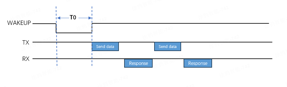
- Support for pulse-based wake-up varies by the key and version of the Zigbee module firmware.
- Pulse-based wake-up applies only to the MCU waking up the module, not vice versa.
- The recommended T0 pulse width for ZS series modules is 1 to 5 milliseconds, while for ZT series modules, it should be at least 10 milliseconds.
Auto-baud detection
The Zigbee module supports two baud rates: 9600 bps and 115200 bps. The module supports automatic baud rate detection. Upon initial power up, it alternates between 9600 bps and 115200 bps to query product information. When the MCU responds at one of these rates, the module saves and configures that rate.
- The auto baud rate detection may vary by the key and version of the Zigbee module firmware.
- Auto baud rate detection occurs only during the initial communication between the module and the MCU in factory default mode. Once set, the baud rate cannot be changed.
- For ZT series modules, in addition to automatic baud rate detection, the module also performs serial pin-group polling. It cycles between two groups of serial port pins in a fixed order until it receives the MCU response to the query product information command on one pin group at one baud rate.
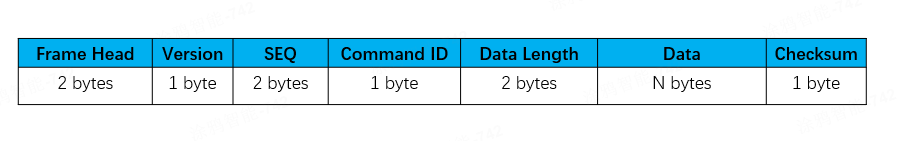
Frame format
| Field | Description |
|---|---|
| Header | It is fixed to 0x55AA |
| Version | The version of the serial protocol, used for protocol updates or extensions. The current version is 0x02. |
| Sequence number (SEQ) | The sequence number for data transmission, cycling from 0 to 0xfff0. This field is represented as xx xx below. |
| Command ID | The ID of a command. Commands are continuously added and updated. |
| Data length | The payload length. |
| Data | The payload data. |
| Checksum | Start from the header, add up all the bytes, and then divide the sum by 256 to get the remainder. This field is represented as xx below. |
The Zigbee module may use packet fragmentation when transmitting data wirelessly, depending on its firmware.
- Packet fragmentation not supported: The maximum
Datasize for sending and receiving is 62 bytes. - Packet fragmentation supported: The maximum
Datasize for receiving is 120 bytes, and for sending, it is 246 bytes. - All data greater than one byte is transmitted in big-endian format.
Command ID
| Command | Sender | Description | Mains-powered version | Low-power version | Scene control version |
|---|---|---|---|---|---|
| 0x01 | Z | Query product information | √ | √ | √ |
| 0x02 | Z | Sync module’s network status | √ | √ | √ |
| 0x03 | M | Reset or pair module | √ | √ | √ |
| 0x00 | Z | Unbind and clear data | √ | √ | √ |
| 0x2B | M | Set wake-up waiting time | × | √ | × |
| 0x07 | M | Query module information | √ | √ | √ |
| 0x20 | M | Query module’s network status | √ | √ | √ |
| 0x25 | M | Check gateway’s network status | √ | √ | × |
| 0x26 | M | Configure Zigbee network parameters | √ | √ | × |
| 0x04 | Z | Receive DP data | √ | √ | √ |
| 0x2A | Z | Receive DP data (group control) | √ | √ | × |
| 0x05 | M | Respond to DP data | √ | √ | √ |
| 0x06 | M | Report DP data (trigger linkage) | √ | √ | √ |
| 0x2C | M | Report DP data (not trigger linkage) | √ | √ | √ |
| 0x28 | Z | Query DP data | √ | √ | √ |
| 0x27 | M | Send advertising packets | √ | √ | √ |
| 0x43 | M | Send private commands via multicast | × | × | √ |
| 0x42 | M | Send standard commands via multicast | × | × | √ |
| 0x41 | Z | Configure scenes | × | × | √ |
| 0x0A | M | Trigger scenes | × | × | √ |
| 0x08 | M | Test module’s RF functionality | √ | √ | √ |
| 0x29 | Z | Notify the MCU of a beacon-triggered test | √ | √ | √ |
| 0x21 | Z | Notify the MCU of a dongle test | √ | √ | √ |
| 0x22 | M | Report dongle test data | √ | √ | √ |
| 0x0B | Z | Query MCU firmware version | √ | √ | √ |
| 0x0C | Z | Initiate OTA update | √ | √ | √ |
| 0x0D | M | Request firmware updates | √ | √ | √ |
| 0x0E | M | Report update result | √ | √ | √ |
| 0x36 | M | Configure GPIO pins | √ | √ | √ |
| 0x37 | M | Read GPIO level | √ | √ | √ |
| 0x38 | M | Control GPIO output | √ | √ | √ |
| 0x39 | M | Sync GPIO interrupt | √ | √ | √ |
| 0x24 | M | Sync time | √ | √ | √ |
| 0x3A | M | Request weather information | √ | √ | √ |
| 0x3B | Z | Sync weather information | √ | √ | √ |
| 0x4A | M | Initiate distributed linkage control | √ | √ | √ |
| 0x4B | M | Configure distributed linkage broadcast DPs | √ | √ | √ |
- M: Refers to the MCU, which sends a command to the Zigbee module.
- Z: Refers to the Zigbee module, which sends a command to the MCU.
Configuration commands
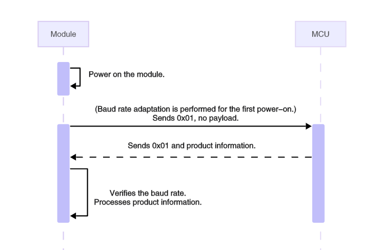
Query product information (0x01)
Each time the Zigbee module is powered on, it sends this command to the MCU, which must respond before sending any other commands to the module. Product information consists of the product ID and the MCU software version number. The Zigbee module also uses this command to check the MCU’s baud rate during their initial communication.
The module sends the following data.
| Field | Bytes | Description |
|---|---|---|
| Header | 2 | 0x55AA |
| Version | 1 | 0x02 |
| Seq. No. | 2 | xx xx |
| Command | 1 | 0x01 |
| Data length | 2 | 0x0000 |
| Data | 0 | None |
| Checksum | 1 | xx |
Example: 55 AA 02 xx xx 01 00 00 xx
The MCU responds with the following data.
| Field | Bytes | Description |
|---|---|---|
| Header | 2 | 0x55AA |
| Version | 1 | 0x02 |
| Seq. No. | 2 | xx xx |
| Command | 1 | 0x01 |
| Data length | 2 | N |
| Data | N | Product information, for example, `{"p":"fj5fqeg9","v":"1.0.0","g":1,"s":1,"lp":1}`. |
| Checksum | 1 | xx |
Product information
Product information is in JSON format, enclosed in curly braces ({}), with data presented as "key":"value" or "key":value. Below are the supported keys and values.
- (Required) p: The product ID (PID) of the product created on the Tuya Developer Platform, such as
fj5fqeg9in the example above. - (Required) v: The MCU firmware version number, in the format
x.y.z, wherexranges from 0 to 3,yfrom 0 to 3, andzfrom 1 to 15. Thus, the possible firmware versions are between 0.0.1 and 3.3.15. - (Optional) g: The flag indicates whether the MCU distinguishes between unicast and multicast (including broadcast) messages. The module will notify the MCU with the command 0x2A upon receiving a multicast message only if g is set to
1. Otherwise, the module sends the command 0x04. It is recommended that the MCU enable this field. - (Optional) s: The flag indicates whether the module needs to support scene features. Scene features are supported only when s is set to
1. Note that this configuration is only supported by the TuyaOS merged version firmware. - (Optional) lp: The flag indicates whether the module is in low power mode. When lp is set to
1, the module is in low power mode and supports low power configurations. Meanwhile, the firmware supports switching between low power mode and router mode. When the device is already connected to a network, switching modes will cause it to first leave the current Zigbee network. Note that this configuration is only supported by the TuyaOS merged version firmware.
Example: 55 AA 02 00 01 01 00 2F 7B 22 70 22 3A 22 66 6A 35 66 71 65 67 39 22 2C 22 76 22 3A 22 31 2E 30 2E 30 22 2C 22 67 22 3A 31 2C 22 73 22 3A 31 2C 22 6C 70 22 3A 31 7D xx
In this example, the product information is: {"p":"fj5fqeg9","v":"1.0.0","g":1,"s":1,"lp":1}.
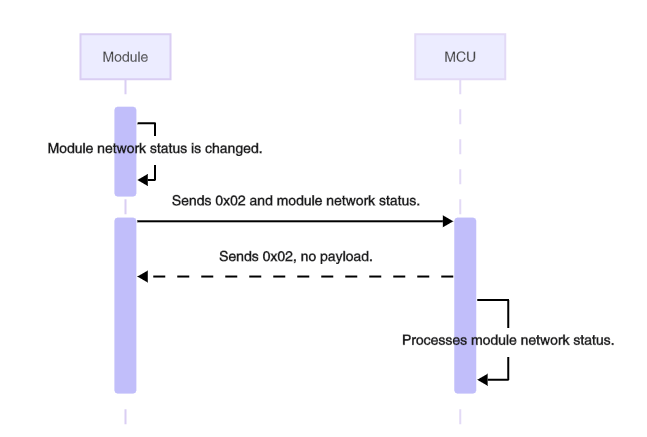
Sync module’s network status (0x02)
The network status refers to the local Zigbee network, not the internet. After the module connects to a gateway, it is considered connected. The network status will remain unchanged despite the loss of gateway power or parent nodes. When the network status of the module changes, the module will proactively send its current status to the MCU.
The module sends the following data.
| Field | Bytes | Description |
|---|---|---|
| Header | 2 | 0x55AA |
| Version | 1 | 0x02 |
| Seq. No. | 2 | xx xx |
| Command | 1 | 0x02 |
| Data length | 2 | 0x0001 |
| Data | 1 | The network status of the module |
| Checksum | 1 | xx |
The network status of the module:
0x00: Not connected, such as when the device is powered on for the first time, fails to pair, or is removed from the mobile app.0x01: Connected, indicating that the device has been added to a Zigbee network.0x02: Network error.0x03: The device is being paired.
Example: 55 AA 02 xx xx 02 00 01 01 xx, indicating the module is connected.
The MCU responds with the following data.
| Field | Bytes | Description |
|---|---|---|
| Header | 2 | 0x55AA |
| Version | 1 | 0x02 |
| Seq. No. | 2 | N |
| Command | 1 | 0x02 |
| Data length | 2 | 0x0000 |
| Data | 0 | None |
| Checksum | 1 | xx |
Example: 55 AA 02 xx xx 02 00 00 xx
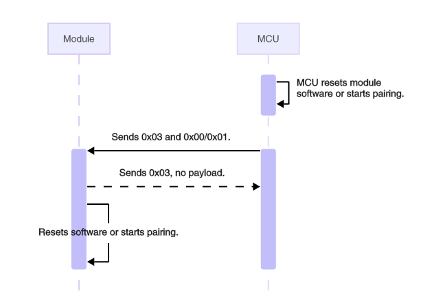
Reset or pair module (0x03)
The MCU instructs the module to enter pairing mode and perform a software reset.
The MCU sends the following data.
| Field | Bytes | Description |
|---|---|---|
| Header | 2 | 0x55AA |
| Version | 1 | 0x02 |
| Seq. No. | 2 | xx xx |
| Command | 1 | 0x03 |
| Data length | 2 | 0x0001 |
| Data | 1 | 0x00: Reset and restart. 0x01: Leave the current network and join a new one. |
| Checksum | 1 | xx |
Example: 55 AA 02 xx xx 03 00 01 01 xx, indicating the module leaves the current network and joins a new one.
The module responds with the following data.
| Field | Bytes | Description |
|---|---|---|
| Header | 2 | 0x55AA |
| Version | 1 | 0x02 |
| Seq. No. | 2 | xx xx |
| Command | 1 | 0x03 |
| Data length | 2 | 0x0000 |
| Data | 0 | None |
| Checksum | 1 | xx |
Example: 55 AA 02 xx xx 03 00 00 xx
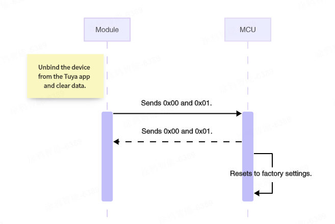
Unbind and clear data (0x00)
When Remove and Clear Data is initiated on the mobile app, the module will notify the MCU of this command. The MCU then clears local data and restores factory settings accordingly.
The module sends the following data.
| Field | Bytes | Description |
|---|---|---|
| Header | 2 | 0x55AA |
| Version | 1 | 0x02 |
| Seq. No. | 2 | xx xx |
| Command | 1 | 0x00 |
| Data length | 2 | 0x0001 |
| Data | 1 | 0x01 (default) |
| Checksum | 1 | xx |
The data field defaults to 0x01, which is reserved for future use.
Example: 55 AA 02 xx xx 00 00 01 01 xx
The MCU responds with the following data.
| Field | Bytes | Description |
|---|---|---|
| Header | 2 | 0x55AA |
| Version | 1 | 0x02 |
| Seq. No. | 2 | N |
| Command | 1 | 0x00 |
| Data length | 2 | 0x0001 |
| Data | 1 | 0x01 |
| Checksum | 1 | xx |
Example: 55 AA 02 xx xx 00 00 01 01 xx
Set wake-up waiting time (0x2B)
This command is for low power devices. To initiate data exchange with the MCU, the module will pull down the MCU wake-up pin and wait for a period T0 before transmitting data. During this waiting period, the MCU gets ready to receive serial data. You can specify an appropriate T0 for your MCU.
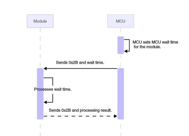
The MCU sends the following data.
| Field | Bytes | Description |
|---|---|---|
| Header | 2 | 0x55AA |
| Version | 1 | 0x02 |
| Seq. No. | 2 | xx xx |
| Command | 1 | 0x2B |
| Data length | 2 | 0x0002 |
| Data | 1 | Default to 5 ms. Valid values range from 3 to 300 milliseconds. |
| Checksum | 1 | xx |
Example: 55 AA 02 xx xx 2B 00 02 00 0A xx, indicating the waiting time is set to 10 ms.
The module returns the following data.
| Field | Bytes | Description |
|---|---|---|
| Header | 2 | 0x55AA |
| Version | 1 | 0x02 |
| Seq. No. | 2 | xx xx |
| Command | 1 | 0x2B |
| Data length | 2 | 0x0001 |
| Data | 1 | 0x00: Failure. 0x01: Success. |
| Checksum | 1 | xx |
Example: 55 AA 02 xx xx 2B 00 01 01 xx, indicating success.
Query module’s information (0x07)
MCU can send this command to the module to query the firmware version number, authorization information, and MAC address of the module.
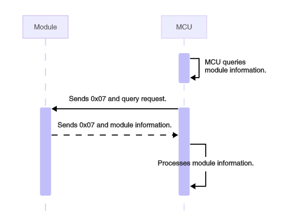
The MCU sends the following data.
| Field | Bytes | Description |
|---|---|---|
| Header | 2 | 0x55AA |
| Version | 1 | 0x02 |
| Seq. No. | 2 | xx xx |
| Command | 1 | 0x07 |
| Data length | 2 | N |
| Data | 1 | One or more module information IDs can be requested. |
| Checksum | 1 | xx |
Module info ID | Description
| Module info ID | Description |
|---|---|
| 0x01 | The module firmware version number. |
| 0x02 | The module authorization information. |
| 0x03 | The module MAC address. |
Example 1: 55 AA 02 xx xx 07 00 01 01 xx indicates to request the module firmware version number.
Example 2: 55 AA 02 xx xx 07 00 02 01 03 xx indicates to request the module firmware version number and MAC address.
The module returns the following data.
| Field | Bytes | Description |
|---|---|---|
| Header | 2 | 0x55AA |
| Version | 1 | 0x02 |
| Seq. No. | 2 | xx xx |
| Command | 1 | 0x07 |
| Data length | 2 | N |
| Data | 1 | The module information is returned in the request order. |
| Checksum | 1 | xx |
Module information
| Data field | Length | Description |
|---|---|---|
| type | 1 | The type. Valid values: 1, 2, and 3 |
| Data | 1/8 |
|
Query module’s network status (0x20)
When the module’s network status changes, it will notify the MCU via the Sync Module’s Network Status. The MCU can also request the module’s current network status.
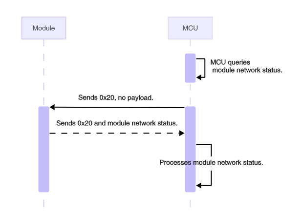
The MCU sends the following data.
| Field | Bytes | Description |
|---|---|---|
| Header | 2 | 0x55AA |
| Version | 1 | 0x02 |
| Seq. No. | 2 | xx xx |
| Command | 1 | 0x20 |
| Data length | 2 | 0x0000 |
| Data | 0 | None |
| Checksum | 1 | xx |
Example: 55 AA 02 xx xx 20 00 00 xx
The module responds with the following data.
| Field | Bytes | Description |
|---|---|---|
| Header | 2 | 0x55AA |
| Version | 1 | 0x02 |
| Seq. No. | 2 | xx xx |
| Command | 1 | 0x20 |
| Data length | 2 | 0x0001 |
| Data | 1 | The network status of the module: |
| Checksum | 1 | xx |
See Sync Module’s Network Status for the network status details.
Example: 55 AA 02 xx xx 20 00 01 01 xx, indicating the module is connected.
Check gateway’s network status (0x25)
The MCU checks the network status of the Zigbee gateway. If the gateway indicates it is online, the Zigbee device is also considered online. The MCU can signify the network status accordingly.
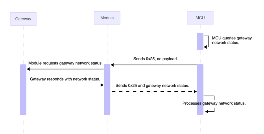
The MCU sends the following data.
| Field | Bytes | Description |
|---|---|---|
| Header | 2 | 0x55AA |
| Version | 1 | 0x02 |
| Seq. No. | 2 | xx xx |
| Command | 1 | 0x25 |
| Data length | 2 | 0x0000 |
| Data | 0 | None |
| Checksum | 1 | xx |
Example: 55 AA 02 xx xx 25 00 00 xx
The module responds with the following data.
| Field | Bytes | Description |
|---|---|---|
| Header | 2 | 0x55AA |
| Version | 1 | 0x02 |
| Seq. No. | 2 | xx xx |
| Command | 1 | 0x25 |
| Data length | 2 | 0x0001 |
| Data | 1 | 0x00: The gateway is offline on the internet. 0x01: The gateway is online on the internet. 0x02: The gateway response times out. |
| Checksum | 1 | xx |
Example: 55 AA 02 xx xx 25 00 01 01 xx, indicating the gateway is online on the internet.
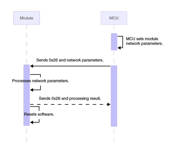
Configure Zigbee network parameters (0x26)
This command configures the network parameters.
- For standard power devices, you only need to specify two parameters: pairing timeout and transmit power.
- For low power Zigbee devices, review the wake-up and data transmission mechanisms before proceeding.
Low power parameters
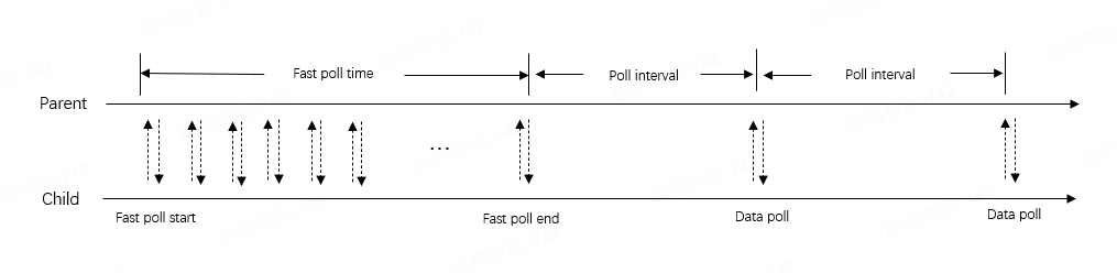
According to the Zigbee protocol, low power devices join a Zigbee network by forming a parent-child relationship with a standard power device such as a router or gateway. Low power devices are in sleep mode most of the time to save energy, during which any messages sent to them are stored on their parent device. A low power device can wake up at the specified poll interval to poll for data from its parent device. If the parent device has cached data, it sends the data to the child device. Otherwise, the child device can return to sleep.
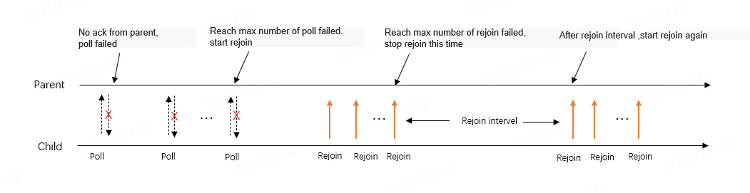
If a child device receives no response from the parent device while polling for data, possibly because the parent is powered off, the poll fails. When the maximum number of failed requests is reached, the child device considers the parent lost and will attempt to find a new parent device to rejoin the original Zigbee network. When the maximum number of failed rejoins is reached, the child device stops and will attempt to rejoin after a specified rejoin interval.
Description of low power parameters:
- Poll interval: The wake-up frequency of a device in sleep mode. Set a short poll interval for devices that receive real-time data, such as 250 ms for a smart switch (no neutral wire required) and 1,000 ms for a door lock. Sensor devices can disable periodic wake-up by setting the poll interval to 0, preventing the module from waking up automatically. The MCU can wake up the module when there is data to report. Shorter poll intervals improve real-time data transmission from the gateway, but they compromise power efficiency.
- Max failed poll times: The maximum number of failed poll attempts. When it is reached, a rejoin will be triggered.
- Fast poll time: The total duration of the fast poll. The module starts a fast poll when the device is paired, powered on, or rejoined. A fast poll accelerates data exchange with the gateway, using a default interval of 250 ms.
- Rejoin interval: The time gap between a failed rejoin and the next attempt, defaulting to 3 minutes. A rejoin is triggered only after the loss of a parent node. The rejoin interval refers to the time gap between each round of rejoin attempts, not the interval for sending rejoin requests.
In each round, multiple rejoin requests are sent. You can set the max rejoin times to specify the maximum number of rejoin requests sent per round. - Max rejoin times: The maximum number of rejoin requests sent per round. Rejoin will automatically stop once a request is successful. If rejoin fails after reaching the max rejoin times, the process will stop and wait for the next round. Alternatively, wait for the next rejoin attempt to be triggered by a message from the MCU.
Proactive heartbeat interval
This command sets the interval for proactive heartbeat checks between a sub-device and the gateway. The Zigbee device regularly sends a heartbeat packet to the Tuya-enabled Zigbee gateway to check if their data link works properly.
-
When the gateway does not receive a heartbeat packet from a low-power device for an extended period, it considers the device offline and syncs with the mobile app for a status update.
-
For standard power devices, the gateway proactively accesses them as a heartbeat check.
-
You can currently adjust the heartbeat interval only for low-power devices, not for standard power devices.
Pairing timeout
When the MCU sends a pairing command, the module initiates the pairing process. The MCU can set the pairing timeout between 30 and 600 seconds, which defaults to 180 seconds. After pairing starts, the module will notify the MCU of changes in network status, including being paired, pairing timeout, and paired successfully.
Transmit power
The power at which the module transmits data wirelessly. The default value is 11 dBm, with a range of 3 to 19 dBm, depending on the module’s chip platform.
The MCU sends the following data.
| Field | Bytes | Description |
|---|---|---|
| Header | 2 | 0x55AA |
| Version | 1 | 0x02 |
| Seq. No. | 2 | xx xx |
| Command | 1 | 0x26 |
| Data length | 2 | 0x000E |
| Data | 0x0E | Zigbee network parameters |
| Checksum | 1 | xx |
Zigbee network parameters
| Byte offset | Parameter | Applicability | Description |
|---|---|---|---|
| 2 | Heartbeat interval | Low power | Valid values range from 10 to 5 × 3,600 seconds. The default is 4 hours (4 × 3,600 seconds). |
| 2 | Pairing timeout | Generic | Valid values range from 30 to 600 seconds. The default is 180 seconds. |
| 2 | Rejoin interval | Low power | Valid values range from 3 to 3,600 seconds. The default is 180 seconds. If the parent node is lost, the module will attempt to rejoin every 180 seconds. |
| 2 | Poll interval | Low power | Valid values are 0 or a range from 200 to 10,000 milliseconds. A value of 0 disables automatic wake-up. The default is 5,000 milliseconds. |
| 2 | Fast poll time | Low power | Valid values range from 10 to 3,000 seconds. The default is 30 seconds. |
| 1 | Max failed poll times | Low power | Valid values range from 3 to 40. When the specified value is reached, a rejoin will be triggered. The default is 4. |
| 1 | Rejoin triggered by MCU message | Low power | 0: Disable 1: Enable (default). Specify if a message from the MCU can trigger a rejoin when the parent node is lost. |
| 1 | Max rejoin times | Low power | Valid values rang from 1 to 10, defaulting to 1. |
| 1 | Transmit power | Generic | Valid values range from 3 to 19 dBm. The default is 11. The maximum transmit power varies by chip platform. See the datasheet for details. For example, ZT and ZP series modules support up to 11 dBm. |
Special values of the Zigbee network parameters:
- 2-byte parameter:
0xFFFFindicates that the last configured value is used, while0xFFFEsignifies that the default value is applied. - 1-byte parameter:
0xFFindicates that the last configured value is used, while0xFEsignifies that the default value is applied.
Example: 55 AA 02 xx xx 26 00 0E FF FE 00 64 FF FE 07 D0 00 32 FE 01 FE FE xx
The Zigbee network parameters in this example:
- Heartbeat interval:
0xFFFE, using the default value. For standard power devices, the value ranges randomly between 150 and 180 seconds. For low power devices, it is 4 hours (4 × 3,600 seconds). - Pairing timeout:
0x0064, 100 seconds. - Rejoin interval:
0xFFFE, using the default 180 seconds. - Poll interval:
0x07D0, indicating that the device wakes up every 2,000 milliseconds. - Fast poll time:
0x0032, indicating the total time to enter quick wake-up mode is 50 seconds. - Max failed poll times:
0xFE, using the default 4 times. - Rejoin triggered by MCU message:
0x01, indicating this feature is enabled. - Max rejoin times:
0xFE, using the default 1 time. - The transmit power:
0xFE, using the default 11 dBm.
The module responds with the following data.
| Field | Bytes | Description |
|---|---|---|
| Header | 2 | 0x55AA |
| Version | 1 | 0x02 |
| Seq. No. | 2 | xx xx |
| Command | 1 | 0x26 |
| Data length | 2 | 0x0001 |
| Data | 1 | 0x00: Failure. 0x01: Success. |
| Checksum | 1 | xx |
Example: 55 AA 02 xx xx 26 00 01 01 xx, indicating success.
Application data transmission commands
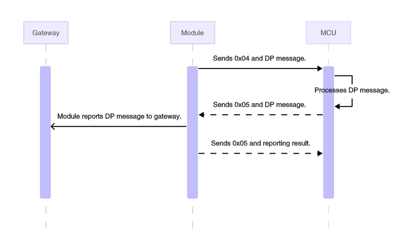
Receive DP data (0x04)
When the module receives a DP message from a Zigbee gateway or sub-device, it notifies the MCU using this command. For example, when you send a DP message to a device using the Tuya app, the message is delivered to the gateway, which then sends it to the target device through the Zigbee network. After receiving the command, the MCU needs to respond to the respective DP message so that the Tuya app can update the device status accordingly.
The module sends the following data.
| Field | Bytes | Description |
|---|---|---|
| Header | 2 | 0x55AA |
| Version | 1 | 0x02 |
| Seq. No. | 2 | xx xx |
| Command | 1 | 0x04 |
| Data length | 2 | N |
| Data | N | DP message format |
| Checksum | 1 | xx |
DP message format:
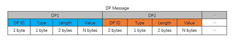
A DP message can include data from multiple DPs, with each DP’s data formatted as follows:
- DP ID: The ID of a DP defined on the Tuya Developer Platform.
- Type: The date type of DP. Some data types have a fixed length.
- Length: The length of the data in the
Valuefield. - Value: The payload.
Type:
| Type | Data type | Data length | Description |
|---|---|---|---|
| 0x00 | Raw | Custom | Raw data type in hex format, with customizable bytes. |
| 0x01 | Boolean | 1 | Boolean data type. Valid values include 0x00 and 0x01. |
| 0x02 | Value | 4 | Value data type, for example, 1, 23, and 104. |
| 0x03 | String | Custom | Custom string. |
| 0x04 | Enum | 1 | Enum data type, ranging from 0 to 255. |
| 0x05 | Bitmap | 1/2/4 | Bitmap data type, used to report error codes. |
Example: 55 AA 02 xx xx 04 00 05 03 01 00 01 01 xx, indicating the module received a DP message with data for one DP, as follows.
- DP ID:
03 - Type:
01 - Length:
00 01 - Value:
01
- A DP message can contain the data structures of multiple DPs, for example, when the mobile app sends several DPs to the device simultaneously.
- The raw type DP has only one data structure. Multiple raw type DPs cannot be sent simultaneously or combined with other types of DPs in one message.
The MCU returns the following data.
| Field | Bytes | Description |
|---|---|---|
| Header | 2 | 0x55AA |
| Version | 1 | 0x02 |
| Seq. No. | 2 | xx xx |
| Command | 1 | 0x04 |
| Data length | 2 | 0x0000 |
| Data | 0 | None |
| Checksum | 1 | xx |
Example: 55 AA 02 xx xx 04 00 00 xx
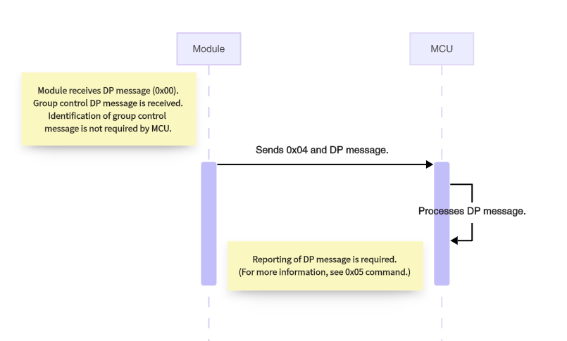
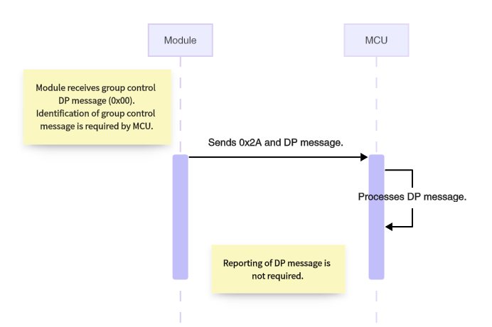
Receive DP data for group control (0x2A)
When the module receives DP messages for group control, including multicast and broadcast, it notifies the MCU with this command. If a Tuya-enabled gateway is connected, the MCU is not required to respond to the received DP message because the gateway can automatically read the DP after sending a group control message.
The Data field of this command is the same as that of Receive DP Data (0x04).
- Legacy Zigbee firmware versions may only support the command
0x04and not this command. - This command only works when the MCU specifies
"g":1in its response to the product information query (0x01). Otherwise, after receiving a group control message, the module notifies the MCU using the command 0x04.
The module sends the following data.
| Field | Bytes | Description |
|---|---|---|
| Header | 2 | 0x55AA |
| Version | 1 | 0x02 |
| Seq. No. | 2 | xx xx |
| Command | 1 | 0x2A |
| Data length | 2 | N |
| Data | N | DP message format |
| Checksum | 1 | xx |
Example: 55 AA 02 xx xx 2A 00 04 01 01 00 01 01 xx, indicating the module received a DP message for group control.
- DP ID:
01 - Type:
00 - Length:
01 - Value:
01
The MCU responds with the following data.
| Field | Bytes | Description |
|---|---|---|
| Header | 2 | 0x55AA |
| Version | 1 | 0x02 |
| Seq. No. | 2 | xx xx |
| Command | 1 | 0x2A |
| Data length | 2 | 0x0000 |
| Data | 0 | None |
| Checksum | 1 | xx |
Example: 55 AA 02 xx xx 2A 00 00 xx
Respond to DP data (0x05)
The MCU can respond to the received DP message (0x04) with this command to sync the DP status with the cloud and mobile app. The Data field of this command is the same as that of the command 0x04.
The MCU sends the following data.
| Field | Bytes | Description |
|---|---|---|
| Header | 2 | 0x55AA |
| Version | 1 | 0x02 |
| Seq. No. | 2 | xx xx |
| Command | 1 | 0x05 |
| Data length | 2 | N |
| Data | N | DP message format |
| Checksum | 1 | xx |
Example: 55 AA 02 xx xx 05 00 05 03 01 00 01 01 xx, indicating the MCU responds to the received DP message.
- DP ID:
03 - DP type:
01 - DP length:
00 01 - DP value:
01
The module responds with the following data.
| Field | Bytes | Description |
|---|---|---|
| Header | 2 | 0x55AA |
| Version | 1 | 0x02 |
| Seq. No. | 2 | xx xx |
| Command | 1 | 0x05 |
| Data length | 2 | 0x0001 |
| Data | 1 | 0x00: Failure. 0x01: Success. |
| Checksum | 1 | xx |
Example: 55 AA 02 xx xx 05 00 01 01 xx
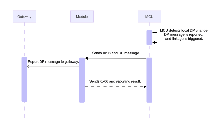
Report DP data (trigger linkage) (0x06)
When the MCU detects a change in DP status, such as when the user presses a switch, it can report the updated DP to the module with this command to sync with the cloud. The module sends the received message to the gateway and waits for its response before replying to the MCU. Reporting DP data through this command can trigger a local or cloud linkage.
-
If the gateway acknowledges the data reporting within the timeout, the module responds to the MCU with success.
-
If the gateway fails to acknowledge the data reporting within the timeout, the module responds to the MCU with failure.
-
If the module is not paired, it should immediately respond to the MCU with failure.
-
The MCU can check if the connection between the module and the gateway works fine based on the module’s response.
The MCU sends the following data.
| Field | Bytes | Description |
|---|---|---|
| Header | 2 | 0x55AA |
| Version | 1 | 0x02 |
| Seq. No. | 2 | xx xx |
| Command | 1 | 0x06 |
| Data length | 2 | N |
| Data | N | DP message format |
| Checksum | 1 | xx |
Example: 55 AA 02 xx xx 06 00 05 03 01 00 01 01 xx
This example shows the MCU proactively reporting a single DP, which can trigger a linkage.
- DP ID:
03 - DP type:
01 - DP length:
00 01 - DP value:
01
The module responds with the following data.
| Field | Bytes | Description |
|---|---|---|
| Header | 2 | 0x55AA |
| Version | 1 | 0x02 |
| Seq. No. | 2 | xx xx |
| Command | 1 | 0x06 |
| Data length | 2 | 0x0001 |
| Data | 1 | 0x00: Failure. 0x01: Success. |
| Checksum | 1 | xx |
Example: 55 AA 02 xx xx 06 00 01 01 xx, indicating the DP message is reported successfully.
- Successful reporting: The module sends the DP message to the gateway and receives an acknowledgment in return.
- Failed reporting: The module is not paired, or the gateway acknowledgment times out.
- Data payload can contain only one raw type DP, which cannot be combined with other types of DPs for reporting.
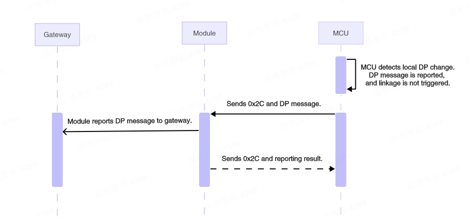
Report DP data (not trigger linkage) (0x2C)
This is an extended command of 0x06, used to send device status to the cloud without directly triggering a linkage. For example, in a linkage where the light turns on when the switch is on and off when it is turned back. When the switch is turned off and then on, its status will sync with the cloud. If you want to prevent this sync from triggering a linkage action on the light, this command allows you to report data without initiating a linkage.
-
After the device is paired or powered on, it is recommended to report DP data with this command to sync status. To prevent network congestion from simultaneous large-volume reporting, specify a random delay of 5 to 15 seconds.
-
Check if the module and firmware you are using support this command.
The MCU sends the following data.
| Field | Bytes | Description |
|---|---|---|
| Header | 2 | 0x55AA |
| Version | 1 | 0x02 |
| Seq. No. | 2 | xx xx |
| Command | 1 | 0x2C |
| Data length | 2 | N |
| Data | N | DP message format |
| Checksum | 1 | xx |
Example: 55 AA 02 xx xx 2C 00 05 03 01 00 01 01 xx
This example shows the MCU proactively reporting a single DP to sync with the cloud, without triggering a linkage.
- DP ID:
03 - DP type:
01 - DP length:
00 01 - DP value:
01
The module responds with the following data.
| Field | Bytes | Description |
|---|---|---|
| Header | 2 | 0x55AA |
| Version | 1 | 0x02 |
| Seq. No. | 2 | xx xx |
| Command | 1 | 0x2C |
| Data length | 2 | 0x0001 |
| Data | 1 | 0x00: Failure. 0x01: Success. |
| Checksum | 1 | xx |
Example: 55 AA 02 xx xx 2C 00 01 01 xx, indicating the DP message is reported successfully.
- Successful reporting: The module sends the DP message to the gateway and receives an acknowledgment in return.
- Failed reporting: The module is not paired, or the gateway acknowledgment times out.
- Data payload can contain only one raw type DP, which cannot be combined with other types of DPs for reporting.
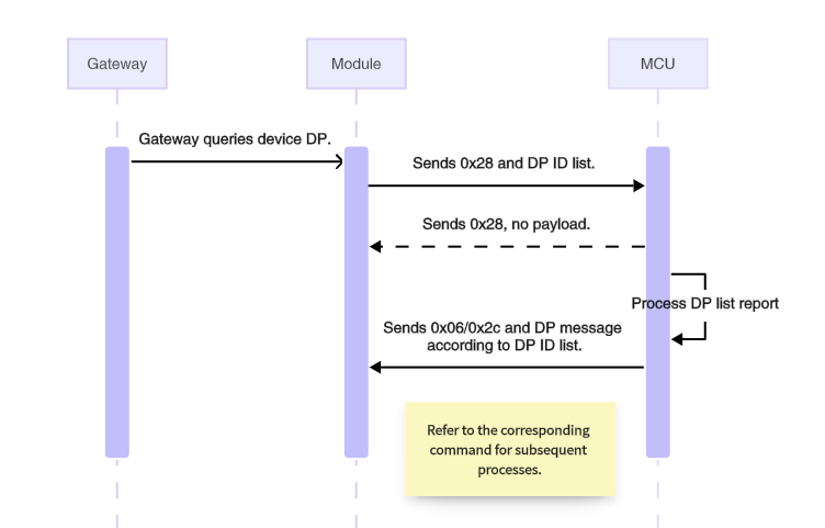
Query DP data (0x28)
The gateway requests the device’s DP with this command. After receiving the request, the MCU acknowledges and then reports the specified DP. This command is typically used when the gateway powers on after a power loss or reconnects to a sub-device following a long disconnection.
The module sends the following data.
| Field | Bytes | Description |
|---|---|---|
| Header | 2 | 0x55AA |
| Version | 1 | 0x02 |
| Seq. No. | 2 | xx xx |
| Command | 1 | 0x28 |
| Data length | 2 | N |
| Data | N | DP ID list |
| Checksum | 1 | xx |
The MCU acknowledges the command and reports DP data using either command 0x2C or the preferred 0x06.
The DP ID list can be specified in two ways:
- The DP ID list is empty, with a data length of 0, indicating that the gateway requests all DPs from the device. The MCU should report all DPs.
- The DP ID list is not empty. For example, it includes
0x01 0x02, indicating the gateway requests the DP IDs0x01and0x02. The MCU should report DP1 and DP2.
Example 1: 55 AA 02 xx xx 28 00 00 xx, indicting the gateway requests all DPs of the device.
Example 2: 55 AA 02 xx xx 28 00 02 01 02 xx, indicting the gateway requests DP1 and DP2 of the device.
The MCU responds with the following data.
| Field | Bytes | Description |
|---|---|---|
| Header | 2 | 0x55AA |
| Version | 1 | 0x02 |
| Seq. No. | 2 | xx xx |
| Command | 1 | 0x28 |
| Data length | 2 | 0x0000 |
| Data | 0 | None |
| Checksum | 1 | xx |
Example: 55 aa 02 xx xx 28 00 01 01 xx
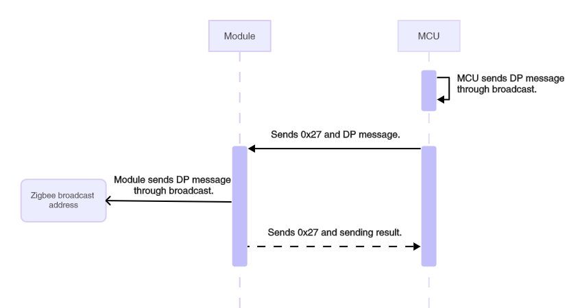
Send advertising packets (0x27)
Broadcast a DP message over the Zigbee network so that all devices can receive it. For low power devices, a periodic wake-up must be specified, with the wake-up interval shorter than the advertising interval. Otherwise, the old packet will be overwritten.
Specify an advertising interval based on the network scale. If not specified, network congestion may occur.
The MCU sends the following data.
| Field | Bytes | Description |
|---|---|---|
| Header | 2 | 0x55AA |
| Version | 1 | 0x02 |
| Seq. No. | 2 | xx xx |
| Command | 1 | 0x27 |
| Data length | 2 | N |
| Data | N | DP message format |
| Checksum | 1 | xx |
Example: 55 AA 02 xx xx 27 08 05 02 00 04 00 00 00 1E xx, an advertising packet with the following content.
- DP ID:
05 - DP type:
02 - DP Length:
00 04 - DP value:
00 00 00 1E
The module responds with the following data.
| Field | Bytes | Description |
|---|---|---|
| Header | 2 | 0x55AA |
| Version | 1 | 0x02 |
| Seq. No. | 2 | xx xx |
| Command | 1 | 0x27 |
| Data length | 2 | 0x0001 |
| Data | 1 | 0x00: Failure. 0x01: Success. |
| Checksum | 1 | xx |
Example: 55 AA 02 xx xx 27 00 01 01 xx, indicating the advertising message is sent successfully.
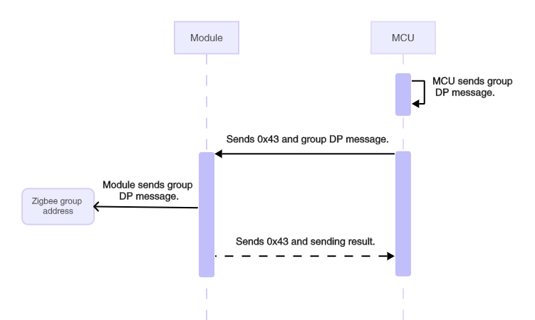
Send DP message to group (0x43)
Send a DP message to a group via multicast to control Tuya-enabled devices. The DP message sent follows the controlled device’s DP format, which includes the DP ID, DP type, DP length, and DP value. The group ID is retrieved through Configure Scenes (for Scene Controllers).
Currently, only scene controller devices support this command. The MCU should be able to assemble messages using the DP format and content of the controlled devices.
The MCU sends the following data.
| Field | Bytes | Description |
|---|---|---|
| Header | 2 | 0x55AA |
| Version | 1 | 0x02 |
| Seq. No. | 2 | xx xx |
| Command | 1 | 0x43 |
| Data length | 2 | N |
| Data | N | DP message format |
| Checksum | 1 | xx |
Example: 55 AA 02 xx xx 43 00 07 2A 08 01 01 00 01 01 xx, sending a DP message via multicast with the following content.
- Group ID:
0x2A08 - DP ID:
01 - DP type:
01 - DP length:
00 01 - DP value:
01
The module returns the following data.
| Field | Bytes | Description |
|---|---|---|
| Header | 2 | 0x55AA |
| Version | 1 | 0x02 |
| Seq. No. | 2 | xx xx |
| Command | 1 | 0x43 |
| Data length | 2 | 0x0001 |
| Data | 1 | 0x00: Failure. 0x01: Success. |
| Checksum | 1 | xx |
Example: 55 AA 02 xx xx 43 00 01 01 xx, indicating the DP message is sent successfully via multicast.
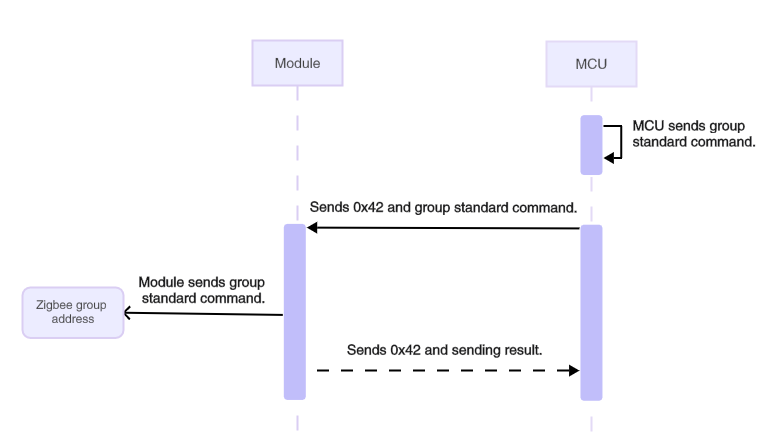
Send standard command to group (0x42)
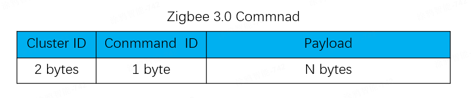
The device sends a standard command to a group via multicast to control devices that support the standard Zigbee commands. The standard commands are outlined in the Zigbee 3.0 specifications, formatted as Cluster ID, Command ID, and payload. The group ID is retrieved through Configure Scenes (for Scene Controllers).
Currently, only scene controller devices support this command. You need to understand the cluster and command format outlined in the Zigbee 3.0 specifications.
The MCU sends the following data.
| Field | Bytes | Description |
|---|---|---|
| Header | 2 | 0x55AA |
| Version | 1 | 0x02 |
| Seq. No. | 2 | xx xx |
| Command | 1 | 0x42 |
| Data length | 2 | N |
| Data | N | Group ID (2 bytes) and standard command format |
| Checksum | 1 | xx |
Format of standard commands:
Example: 55 AA 02 xx xx 42 00 05 2A 08 00 06 01 xx sending a standard command via multicast with the following content.
- Group ID:
0x2A08 - Cluster ID:
0x0006 (On/Off cluster) - Command ID:
0x01 (On) - Payload:
null
The module returns the following data.
| Field | Bytes | Description |
|---|---|---|
| Header | 2 | 0x55AA |
| Version | 1 | 0x02 |
| Seq. No. | 2 | xx xx |
| Command | 1 | 0x42 |
| Data length | 2 | 0x0001 |
| Data | N | 0x00: Failure. 0x01: Success. |
| Checksum | 1 | xx |
Example: 55 AA 02 xx xx 42 00 01 01 xx, indicating the standard command is sent successfully via multicast.
The supported standard commands are listed below. For payload details, see the official Zigbee Cluster Library Specification R8. This specification is provided by the CSA and may be updated in the future.
On/Off Cluster
- On
- Off
- Toggle
Level Control Cluster
- Move to Level
- Move
- Step
- Stop
- Move to Level (with On/Off)
- Move (with On/Off)
- Step (with On/Off)
- Stop
Color Control cluster
- Move to Hue
- Move Hue
- Step Hue
- Move to Saturation
- Move Saturation
- Step Saturation
- Move to Hue and Saturation
- Move to Color
- Move Color
- Step Color
- Move to Color Temperature
- Move Color Temperature
- Step Color Temperature
- Stop Move Step
Window Covering Cluster
- Up/Open
- Down/Close
- Stop
- Go To Lift Value
- Go to Lift Percentage
- Go to Tilt Value
- Go to Tilt Value
Scenes Cluster
- Recall Scene
Scene commands
A scene, also known as a linkage, refers to the execution of a specific action when a condition is met. Conditions can include time, weather, and device status, while actions refer to tasks or commands that a device is instructed to execute. For example, when the temperature sensor detects that the temperature exceeds 30°C, turn on the air conditioner and set it to 25°C.
A scene controller, such as a scene switch and remote, serves as a condition in scenes. It typically has multiple buttons, each used to trigger a scene. For example, press button 1 to turn off all the lights and button 2 to turn them on.
Tuya-enabled Zigbee devices support both standard scenes and linkage scenes.
Standard scene
Standard scene: The scenes outlined in the Zigbee Cluster Library Specification by CSA. Creating a standard scene requires a gateway to send configurations. Once created, it can be triggered independently of the gateway. Even if the gateway loses power, the scene can function because the scene controller directly sends control commands to the target device.
Creating a standard scene requires the following:
- Access to scene creation: Open the app panel of the scene controller and select a button to create a scene.
- Actuator: A Zigbee device that performs the specified action and must be on the same gateway as the scene controller. You can add multiple actuators, but groups are not allowed. When a group is added as an actuator, it will be converted into a linkage scene automatically.
The following figures show how to create and recall a standard scene.
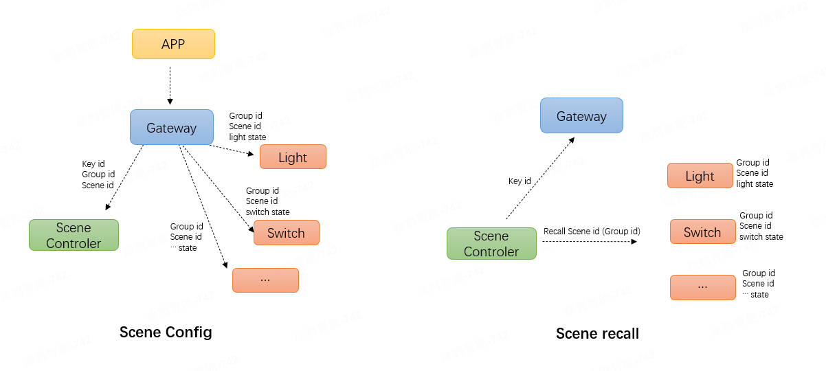
-
Configure a standard scene: After the mobile app creates a standard scene, it sends the key ID, group ID, and scene ID to the scene controller via the gateway. The controller then sends the group address, scene ID, and action to the controlled device. The scene controller and the controlled devices are therefore grouped together, allowing the scene controller to send commands to that group address.
-
Recall a standard scene: Pressing a scene controller button sends a scene recall command to the corresponding group address. The controlled device receives this message and changes to the state defined by the scene ID.
Linkage scene
Linkage scene: Using a gateway or cloud as an intermediary, the trigger device reports its status to the gateway, which then verifies whether the linkage has been managed locally. A scene managed locally is called gateway linkage, while a scene managed in the cloud is referred to as cloud linkage.
- Gateway linkage: The Zigbee gateway stores linkage data. When a trigger device reports its status, the gateway controls the actuator based on this stored data. For example, gateway linkage applies when both the temperature sensor and air conditioner are connected to the same gateway.
- Cloud linkage: The cloud stores linkage data. When a trigger device reports its status to the gateway, the gateway forwards this information to the cloud, which then controls the actuator based on the stored data. For example, when a Zigbee device serves as a trigger and a Wi-Fi device acts as an actuator, cloud linkage is typically used.
You do not need to check whether a linkage scene is gateway or cloud-based. The Tuya Developer Platform determines the type based on the device type selected by the user during scene creation.
Scene commands apply only to scene controllers and require specific module firmware. The type of scene depends on how users create it.
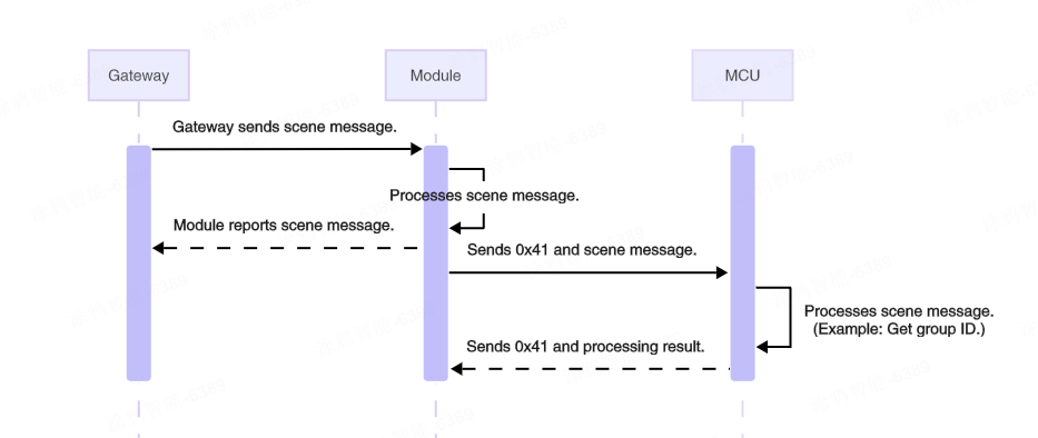
Configure scenes (0x41)
This command requires specific module firmware and applies to scene controller devices. The module notifies the MCU of the received key ID, group address, and scene ID from the gateway.
The module sends the following data.
| Field | Bytes | Description |
|---|---|---|
| Header | 2 | 0x55AA |
| Version | 1 | 0x02 |
| Seq. No. | 2 | xx xx |
| Command | 1 | 0x41 |
| Data length | 2 | 0x0004 |
| Data | 4 | Key ID (1 byte) + Group ID (2 bytes) + Scene ID (1 byte) |
| Checksum | 1 | xx |
Example: 55 AA 02 xx xx 41 00 04 01 00 02 02 xx, indicating that a scene configuration command is received from the gateway.
- Key ID:
01 - Group ID:
0x0002 - Scene ID:
0x02
The MCU responds with the following data.
| Field | Bytes | Description |
|---|---|---|
| Header | 2 | 0x55AA |
| Version | 1 | 0x02 |
| Seq. No. | 2 | xx xx |
| Command | 1 | 0x41 |
| Data length | 2 | 0x0001 |
| Data | 1 | 0x00: Failure. 0x01: Success. |
| Checksum | 1 | xx |
Example: 55 AA 02 xx xx 41 00 01 01 xx
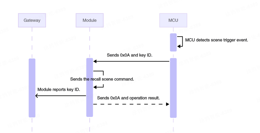
Trigger scenes (0x0A)
Trigger standard scenes and cloud scenes. A cloud scene is created using the Tuya-enabled mobile app instead of the scene controller’s app panel. The controller acts as a trigger for the linkage. When a button is pressed, the controller sends a standard scene recall command and reports the key ID to the gateway to trigger a cloud linkage. If no standard scene is available, this command is used only to trigger a cloud linkage.
This command requires specific module firmware and applies to scene controller devices.
The MCU sends the following data.
| Field | Bytes | Description |
|---|---|---|
| Header | 2 | 0x55AA |
| Version | 1 | 0x02 |
| Seq. No. | 2 | xx xx |
| Command | 1 | 0x0A |
| Data length | 2 | 0x0001 |
| Data | 1 | The key ID. |
| Checksum | 1 | xx |
Example: 55 AA 02 xx xx 0A 00 01 01 xx, triggering a scene with key ID 1.
The module responds with the following data.
| Field | Bytes | Description |
|---|---|---|
| Header | 2 | 0x55AA |
| Version | 1 | 0x02 |
| Seq. No. | 2 | xx xx |
| Command | 1 | 0x0A |
| Data length | 2 | 0x0001 |
| Data | 1 | 0x00: Failure. 0x01: Success. |
| Checksum | 1 | xx |
Example: 55 AA 02 xx xx 0A 00 01 01 xx, indicating the scene is triggered successfully. The operation is considered successful if either a cloud linkage or a standard scene is triggered.
Production testing commands
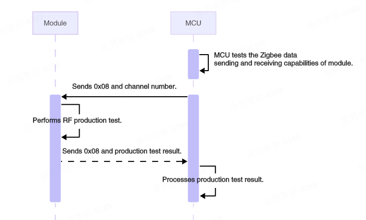
Test module’s RF functionality (0x08)
This command tests the module’s RF transmission and reception. Prepare a test dongle and switch it to RF mode to conduct the test. See Set Zigbee Dongle for details. After receiving this command, the module typically sends 100 raw data packets wirelessly. The dongle returns each received packet in a loopback manner. With the receive mode enabled, the module checks the incoming data. If the received data matches the sent data, it is considered valid. The module then returns the count of received packets to the MCU.
The module under test must be unpaired. After the test is complete, restart the module to return to normal operation mode. The default channel is channel 11.
The MCU sends the following data.
| Field | Bytes | Description |
|---|---|---|
| Header | 2 | 0x55AA |
| Version | 1 | 0x02 |
| Seq. No. | 2 | xx xx |
| Command | 1 | 0x08 |
| Data length | 2 | 0x0001 |
| Data | 1 | The channel ID, ranging from 11 to 26. |
| Checksum | 1 | xx |
The channel ID must match the one configured on the dongle. Avoid conducting RF tests on multiple devices using the same channel simultaneously to prevent interference.
Example: 55 AA 02 xx xx 08 00 01 0B xx, conducting an RF test on channel 11.
The module responds with the following data.
| Field | Bytes | Description |
|---|---|---|
| Header | 2 | 0x55AA |
| Version | 1 | 0x02 |
| Seq. No. | 2 | xx xx |
| Command | 1 | 0x08 |
| Data length | 2 | 0x0002 |
| Data | 2 | RF test results. |
| Checksum | 1 | xx |
RF test results:
-
Data[0] = 0x00, indicating the test failed.
- Data[1] = 0x00, indicating the test failed because the loopback packet was not received.
-
Data[0] = 0x01, indicating the test passed.
- Data[1] = Number of loopback packets, ranging from 1 to 100. A value of 100 indicates that all sent data is looped back from the dongle.
Example: 55 AA 02 xx xx 08 00 02 01 62 xx, indicating the RF test passed, with 98 out of 100 data packets looped back.
Once the RF test is activated, the module sends 100 raw data packets in a specific format, with 20-millisecond intervals between each packet. After the dongle receives a packet, it will loop it back. The module should theoretically receive the same packet it sent out. The test verifies the receiver and transmitter of the modules, excluding signal strength.
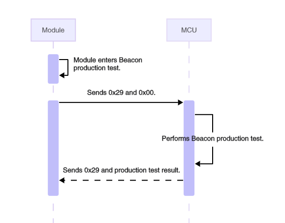
Notify the MCU of a beacon-triggered test (0x29)
To test the end products, prepare a test dongle and set it to beacon mode (BC mode). The dongle will continuously send specific data packets wirelessly, known as beacons. After power on, the module will stay in beacon reception mode for a period, typically 300 milliseconds. When the module receives a beacon from the dongle, it will notify the MCU with this command, allowing the MCU to perform self-checks. For example, conduct tests on lights that cannot be activated by physical triggers to verify if they function properly.
-
Beacon production testing applies only to unpaired devices. After power on, paired devices do not stay within a time window to receive beacons. If pairing takes longer than 15 minutes, beacon production testing will be permanently disabled.
-
The module alternates between 9600 bps and 115200 bps to send beacon production testing notifications.
The module sends the following data.
| Field | Bytes | Description |
|---|---|---|
| Header | 2 | 0x55AA |
| Version | 1 | 0x02 |
| Seq. No. | 2 | xx xx |
| Command | 1 | 0x29 |
| Data length | 2 | 0x0001 |
| Data | 1 | 0x00 |
| Checksum | 1 | xx |
Example: 55 AA 02 xx xx 29 00 01 00 xx, indicating the module receives a beacon from the test dongle within the time window after power on.
The MCU responds with the following data.
| Field | Bytes | Description |
|---|---|---|
| Header | 2 | 0x55AA |
| Version | 1 | 0x02 |
| Seq. No. | 2 | xx xx |
| Command | 1 | 0x29 |
| Data length | 2 | 0x0001 |
| Data | 1 | 0x00: Failure. 0x01: Success. |
| Checksum | 1 | xx |
Example: 55 AA 02 xx xx 29 00 01 01 xx
The module does not check for the success or failure returned by the MCU.
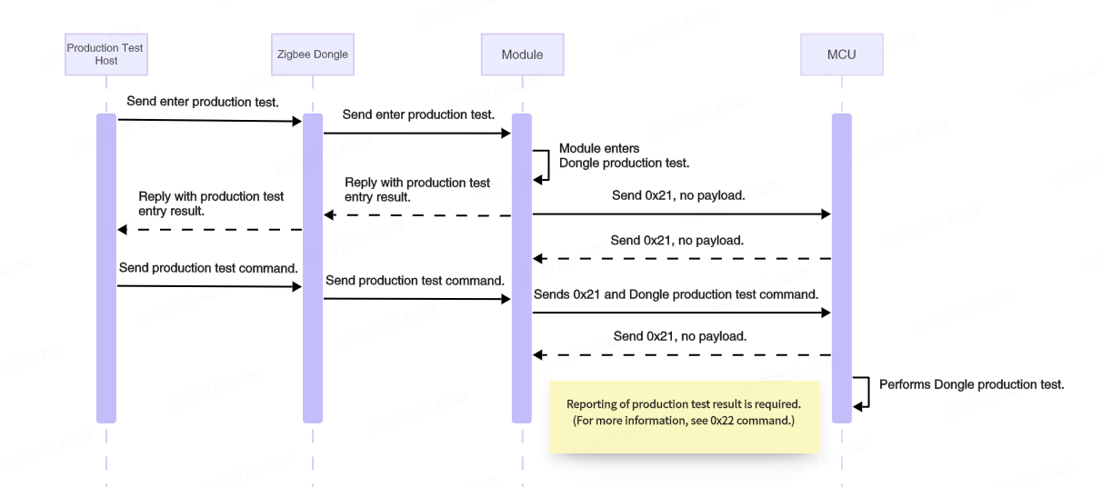
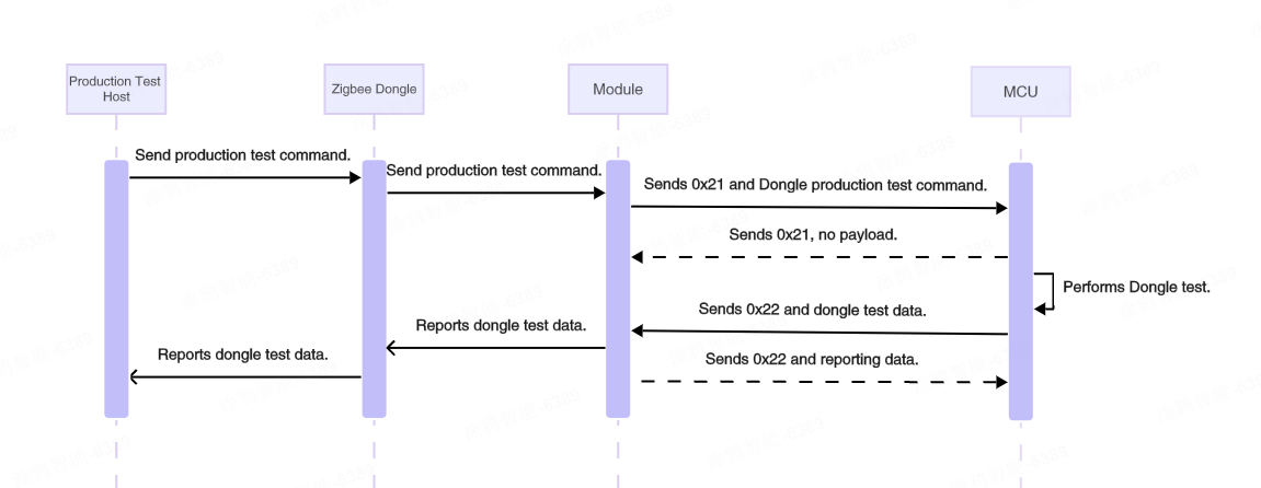
Dongle test notify (0x21)
Dual Dongle production testing refers to the test conducted in the entire machine stage to confirm the various peripherals and RF performance of the entire machine equipment. Equipment that meets the finished product requirements can be screened in the last stage of leaving the factory.
Before the Dongle production testing, two test Dongles must be prepared and configured as the Test Receiver (TS) and the Test Beacon (BC) respectively. The host computer can then send and receive specific test item content via these Dongles.
The Module transparently transmits the production test data to the MCU via this command. Upon receipt, the MCU parses the Dongle production test data, executes the corresponding test items, and reports the test results via Dongle test result report.
-
Dongle production testing applies only to unpaired devices. After power on, paired devices do not stay within a time window to receive beacons. If pairing takes longer than 15 minutes, production testing will be permanently disabled.
-
When entering the Dongle production test, the module may not have gotten a baud rate. In this case, baud rates 9600 and 115200 are used for sending the notification for entering the Dongle production test 3 times.
The module sends the following data.
| Field | Bytes | Description |
|---|---|---|
| Header | 2 | 0x55AA |
| Version | 1 | 0x02 |
| Seq. No. | 2 | xx xx |
| Command | 1 | 0x21 |
| Data length | 2 | N |
| Data | N | Dongle production test data If the module enters the Dongle production test, the data is empty, and the data length is 0. If production test data is received from the host, the data is passed through. |
| Checksum | 1 | xx |
The MCU responds with the following data.
| Field | Bytes | Description |
|---|---|---|
| Header | 2 | 0x55AA |
| Version | 1 | 0x02 |
| Seq. No. | 2 | xx xx |
| Command | 1 | 0x21 |
| Data length | 2 | 0x0000 |
| Data | 0 | None |
| Checksum | 1 | xx |
Dongle test result report (0x22)
The module sends the following data.
| Field | Bytes | Description |
|---|---|---|
| Header | 2 | 0x55AA |
| Version | 1 | 0x02 |
| Seq. No. | 2 | xx xx |
| Command | 1 | 0x22 |
| Data length | 2 | N |
| Data | N | Dongle test data |
| Checksum | 1 | xx |
Dongle test data ID
| Type | ID |
|---|---|
| DONGLE_MF_RESULT_CMD | 0x01 |
| DONGLE_MF_BUTTON_NOTIFY | 0x02 |
| DONBLE_MF_BOOL_NOTIFY | 0x03 |
| DONBLE_MF_GENERAL_SEND | 0x04 |
DONGLE_MF_RESULT_CMDformat
| CMD ID | Result |
|---|---|
| 0x01 |
|
DONGLE_MF_BUTTON_NOTIFYformat
| CMD ID | Key ID |
|---|---|
| 0x02 | 4 Bytes Little-endian byte ordering |
DONBLE_MF_BOOL_NOTIFYformat
| CMD ID | Sensor Type | Index | Result |
|---|---|---|---|
| 0x03 | Sensor type | index | result
|
DONBLE_MF_GENERAL_SENDformat
| CMD ID | CMD | Len | Data |
|---|---|---|---|
| 0x04 | Command type | Data length | Data |
The module responds with the following data.
| Field | Bytes | Description |
|---|---|---|
| Header | 2 | 0x55AA |
| Version | 1 | 0x02 |
| Seq. No. | 2 | xx xx |
| Command | 1 | 0x22 |
| Data length | 2 | 0x0001 |
| Data | 1 | 0x00: Failure. 0x01: Success. |
| Checksum | 1 | xx |
Dongle test example:
-
Notification for entering production test
- MODULE–>MCU:
55 AA 02 xx xx 21 00 00 xx
- MODULE–>MCU:
-
Indicator test
-
MODULE–>MCU:
55 AA 02 xx xx 21 00 03 09 08 02 xx08 02indicates the LED indicator blinks alternately. (The action is determined by the production test JSON data.) -
The test is passed if you can click the LED indicator icon on the production test host, and the test result meets the requirement.
-
-
Key test
-
MODULE–>MCU:
55 AA 02 xx xx 21 00 03 09 0A 00 xx -
MCU–>MODULE:
55 AA 02 xx xx 22 00 05 02 00 00 00 00 xx0x00000000indicates the key ID, and the module converts the key ID into{"keyID":0}and transfers it to Dongle. -
The test is passed if the key is displayed on the production test host.
-
-
Temperature and humidity sensor test 0x0C
-
MODULE–>MCU:
55 AA 02 xx xx 21 00 03 09 0C 00 xx -
MCU–>MODULE:
55 AA 02 xx xx 22 00 19 04 0C 16 7B 22 53 31 22 3A 32 35 30 30 2C 22 53 32 22 3A 38 30 30 30 7D 20 xxSample data:
{"S1":2500,"S2":8000} -
The test is passed if the displayed temperature is 25°C and the displayed humidity is 80% on the production test host.
-
-
Luminance sensor test
-
MODULE–>MCU:
55 AA 02 xx xx 21 00 1D 09 13 7B 22 74 79 70 65 22 3A 22 4C 75 6D 69 6E 61 6E 63 65 22 2C 22 63 68 22 3A 30 7D xxSample data:
{"type":"Luminance","ch":0} -
MCU–>MODULE:
55 AA 02 xx xx 22 00 29 04 13 26 7B 22 74 79 70 65 22 3A 22 4C 75 6D 69 6E 61 6E 63 65 22 2C 22 63 68 22 3A 30 2C 22 76 61 6C 22 3A 31 35 30 30 7D xxSample data:
{"type":"Luminance","ch":0,"val":1500} -
The test is passed if the displayed illuminance is 1,500 lux on the production test host.
-
-
PIR sensor test
- MODULE–>MCU:
55 AA 02 xx xx 21 00 02 0B 01 xx - MCU–>MODULE:
55 AA 02 xx xx 22 00 04 03 01 00 01 xxindicates PIR status TRUE.55 AA 02 xx xx 22 00 04 03 01 00 00 xxindicates PIR status FALSE. - The PIR sensor test of the production test host is passed if the test result meets the requirement.
- MODULE–>MCU:
-
PIR sensor detection range test
-
MODULE–>MCU:
55 AA 02 xx xx 21 00 21 09 13 7B 22 74 79 70 65 22 3A 22 53 65 6E 73 65 44 69 73 74 61 6E 63 65 22 2C 22 63 68 22 3A 30 7D xxSample data:
{"type":"SenseDistance","ch":0} -
MCU–>MODULE:
55 AA 02 xx xx 22 00 2C 04 13 7B 22 74 79 70 65 22 3A 22 53 65 6E 73 65 44 69 73 74 61 6E 63 65 22 2C 22 63 68 22 3A 30 2C 22 76 61 6C 22 3A 35 30 30 7D xxSample data:
{"type":"SenseDistance","ch":0,"val":500} -
The test is passed if the displayed detection range is 500 mV on the production test host.
-
-
Contact sensor test
- MODULE–>MCU:
55 AA 02 xx xx 21 00 02 0B 00 xx - MCU–>MODULE:
55 AA 02 xx xx 22 00 04 03 00 00 01 xxindicates contact sensor status TRUE.55 AA 02 xx xx 22 00 04 03 00 00 00 xxindicates contact sensor status FALSE.
- MODULE–>MCU:
-
Anti-tamper test
- MODULE–>MCU:
55 AA 02 xxxx 21 00 02 0B 07 xx - MCU–>MODULE:
55 AA 02 xx xx 22 00 04 03 07 00 01 xxindicates Anti-tamper status TRUE.55 AA 02 xx xx 22 00 04 03 07 00 00 xxindicates Anti-tamper status FALSE. - The anti-tamper test of the production test host is passed if the test result meets the requirement.
- MODULE–>MCU:
-
Battery voltage test
-
MODULE–>MCU:
55 AA 02 xx xx 21 00 03 09 90 00 xx -
MCU–>MODULE:
55 AA 02 xx xx 22 00 13 04 90 10 7B 22 50 22 3A 31 2C 22 42 22 3A 33 30 30 30 7D xxSample data:
{"P":1,"B":3000} -
The test is passed if the displayed voltage is 3,000 mV on the production test host.
-
MCU OTA update commands
The process to perform an MCU OTA update through the module:
- The gateway requests the MCU firmware version and reports it to the cloud.
- When the cloud detects that the PID (or device ID) has MCU OTA updates configured and a new update is available, it will notify the module to perform the MCU OTA.
- After receiving the notification from the cloud, the module will notify the MCU.
- The MCU requests and installs the update file.
- After the update is complete, report the OTA results and the new MCU firmware version using the response format specified in the MCU Firmware Version Query.
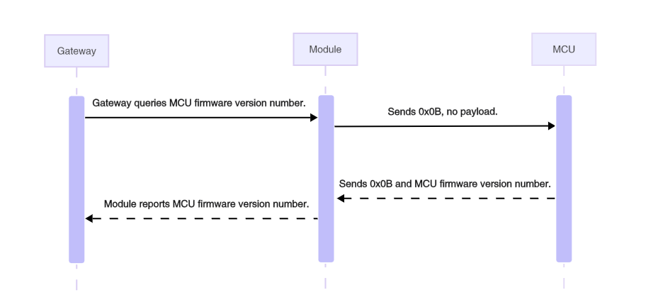
Query MCU firmware version (0x0B)
Sync the current MCU firmware version with the cloud for display or OTA update check. This command must be implemented if you need MCU OTA updates. This command works to:
-
Gateway queries MCU version number: The module notifies the MCU of the gateway’s version query and waits for a response.
-
Device proactively reports MCU version number: For example, after a successful pairing or OTA update, the MCU reports its current version number to the module, which then sends it to the gateway.
The module sends the following data.
| Field | Bytes | Description |
|---|---|---|
| Header | 2 | 0x55AA |
| Version | 1 | 0x02 |
| Seq. No. | 2 | xx xx |
| Command | 1 | 0x0B |
| Data length | 2 | 0x0000 |
| Data | 0 | None |
| Checksum | 1 | xx |
Example: 55 AA 02 xx xx 0B 00 00 xx, querying the current version number of the MCU.
The MCU responds with the following data.
| Field | Bytes | Description |
|---|---|---|
| Header | 2 | 0x55AA |
| Version | 1 | 0x02 |
| Seq. No. | 2 | xx xx |
| Command | 1 | 0x0B |
| Data length | 2 | 0x0001 |
| Data | 1 | The MCU firmware version number (1 byte). |
| Checksum | 1 | xx |
The MCU firmware version number is represented as a single byte in binary format xx.yy.zzzz. For example, 0x40 (binary 01 00 0000) represents the version number 1.0.0. Due to this one-byte limitation, the maximum version number is 3.3.15.
Example: 55 AA 02 xx xx 0B 00 01 53 xx, indicating the current version number is 0x53, which in binary is 0101 0011, corresponding to version 1.1.3.
- The cloud uses this command to retrieve the MCU version number and decide whether to push an OTA update.
- The MCU can proactively send its version number to the module without needing a query, and the module then reports it to the gateway.
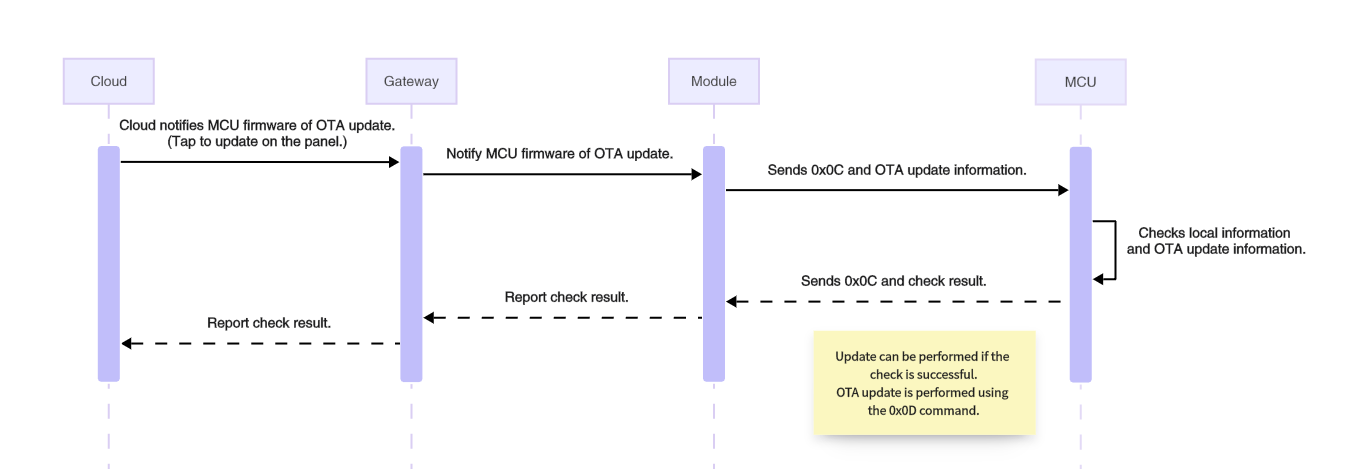
Initiate OTA update (0x0C)
If a product has the MCU OTA update feature configured and the push service enabled on the Tuya Developer Platform, the mobile app will notify users or automatically initiate an update when an update is available. The module receives the command from the gateway and notifies the MCU to prepare for an OTA update.
The module sends the following data.
| Field | Bytes | Description |
|---|---|---|
| Header | 2 | 0x55AA |
| Version | 1 | 0x02 |
| Seq. No. | 2 | xx xx |
| Command | 1 | 0x0C |
| Data length | 2 | 0x0011 |
| Data | 17 | PID (8 bytes) + new firmware version number (1 byte) + firmware size in bytes (4 bytes) + firmware checksum (4 bytes) |
| Checksum | 1 | xx |
- PID (8 bytes): The PID of the current device, for example,
AIp08kLI. - New firmware version number (1 byte): For example,
0x41indicates version 1.0.1. - Firmware size (4 bytes): Measured in bytes.
- Firmware checksum (4 bytes): The checksum of the entire firmware from the first byte. After the MCU receives the complete firmware update, it should calculate the checksum and compare it to this field. If the checksum does not match, an issue may have occurred during transmission, causing the update to fail.
Example: 0x55 AA 02 xx xx 0C 00 11 41 49 70 30 38 6b 4c 49 41 00 00 78 00 30 31 32 33 XX, an OTA update notification with the following content:
- PID:
0x41 49 70 30 38 6b 4c 49, which isAIp08kLI. - New firmware version number:
0x41, which is version 1.0.1. - Firmware size:
0x00007800, which is 30 KB. - Firmware checksum:
0x30313233
The MCU responds with the following data.
| Field | Bytes | Description |
|---|---|---|
| Header | 2 | 0x55AA |
| Version | 1 | 0x02 |
| Seq. No. | 2 | xx xx |
| Command | 1 | 0x0C |
| Data length | 2 | 0x0001 |
| Data | 1 | 0x00: check failed 0x01: check success |
| Checksum | 1 | xx |
Example: 55 AA 02 xx xx 0C 00 01 00 xx
The module currently does not process the MCU response to the command 0x0C. If the MCU detects a data error, it can request the packet to be resent.
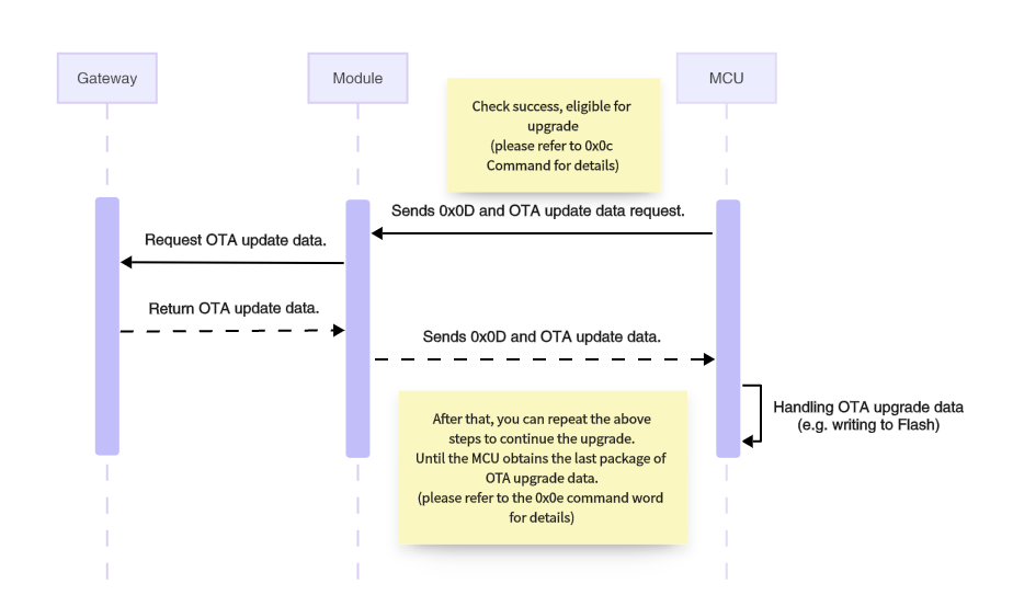
Request firmware updates (0x0D)
After receiving the OTA update notification from the gateway, the device can start downloading the OTA file. The device manages the download process by sending a file request that includes the data offset and packet size. After receiving the request from the device, the gateway returns the packet offset and update data. This command is initiated by the MCU and sent to the gateway by the module.
The MCU sends the following data.
| Field | Bytes | Description |
|---|---|---|
| Header | 2 | 0x55AA |
| Version | 1 | 0x02 |
| Seq. No. | 2 | xx xx |
| Command | 1 | 0x0D |
| Data length | 2 | 0x000E |
| Data | 14 | PID (8 bytes) + new firmware version number (1 byte) + packet offset (4 bytes) + packet size (1 byte) |
| Checksum | 1 | xx |
- PID (8 bytes): The PID of the current device, for example,
AIp08kLI. - New firmware version number (1 byte): For example,
0x41indicates version 1.0.1. - Packet offset (4 bytes): The offset of the requested data in the OTA file, in bytes.
- Packet size (1 byte): The size of the requested packet, in bytes, up to 48 bytes.
Example: 0x55 AA 02 xx xx 0C 00 0E 41 49 70 30 38 6b 4c 49 41 00 00 10 00 30 XX, requesting a 48-byte packet starting from the address 4096.
- PID:
0x41 49 70 30 38 6b 4c 49, which isAIp08kLI. - New firmware version number:
0x41, which is version 1.0.1. - Packet offset:
0x00001000, indicating an offset address of 4096. - Packet size:
0x30, requesting 48 bytes of data.
The module responds with the following data.
| Field | Bytes | Description |
|---|---|---|
| Header | 2 | 0x55AA |
| Version | 1 | 0x02 |
| Seq. No. | 2 | xx xx |
| Command | 1 | 0x0D |
| Data length | 2 | N |
| Data | N | Result (1 byte) + PID (8 bytes) + new firmware version number (1 byte) + packet offset (4 bytes) + payload |
| Checksum | 1 | xx |
- Result:
0x00for success and0x01for failure. When the request fails, there is no following data. - PID (8 bytes): The PID of the current device, for example,
AIp08kLI. - New firmware version number (1 byte): For example,
0x41indicates version 1.0.1. - Packet offset (4 bytes): The offset of the requested data in the OTA file, in bytes.
- Payload (N bytes): The actual data.
Example: 55 AA 02 xx xx 0D xxxx 00 41 49 70 30 38 6b 4c 49 41 00 00 00 32 … xx, indicating a successful request (payload represented by ellipsis).
Report update result (0x0E)
After completing an MCU OTA update, the MCU initiates this command to report the update result to the gateway.
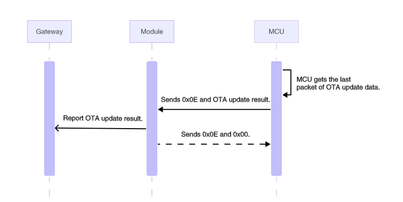
The MCU sends the following data.
| Field | Bytes | Description |
|---|---|---|
| Header | 2 | 0x55AA |
| Version | 1 | 0x02 |
| Seq. No. | 2 | xx xx |
| Command | 1 | 0x0E |
| Data length | 2 | 0x000A |
| Data | 10 | Result (1 byte) + PID (8 bytes) + new firmware version number (1 byte) |
| Checksum | 1 | xx |
- Result (1 byte):
0x00for a successful update and0x01for a failed update.
Example: 0x55 AA 02 xx xx 0E 00 0A 00 41 49 70 30 38 6b 4c 49 41 xx, indicating the MCU OTA update succeeded.
- Result:
0x00, indicating a successful MCU OTA update. - PID:
0x41 49 70 30 38 6b 4c 49, which isAIp08kLI. - New firmware version number:
0x41, which is version 1.0.1.
The module responds with the following data.
| Field | Bytes | Description |
|---|---|---|
| Header | 2 | 0x55AA |
| Version | 1 | 0x02 |
| Seq. No. | 2 | xx xx |
| Command | 1 | 0x0E |
| Data length | 2 | 0x0001 |
| Data | 1 | 0x00: OK. 0x01: Error. |
| Checksum | 1 | xx |
Example: 0x55 AA 02 xx xx 0E 00 01 00 xx
GPIO control commands
The module communicates with the MCU via the UART TX and UART RX pins. The low power module also has two wake-up pins. The module has additional GPIO pins beyond these pins. If the MCU has insufficient GPIO pins, you can use the module’s GPIO pin for input and output. To do this, initialize the module’s GPIO pin with GPIO configurations.
- To configure the module’s GPIO pin as an output, use the command Control GPIO Output to set the output level.
- To configure the module’s GPIO pin as an input, use the command Read GPIO Level to get its current status.
- To configure the module’s GPIO pin as an input interrupt, use the command Sync GPIO Input Interrupt to notify the MCU when the GPIO level changes.
-
Support for GPIO pins as interrupt inputs and output driver capabilities vary by chip platform. Refer to the datasheet for your specific chip.
-
For ZT series modules operating as low-power devices, the GPIO output levels cannot be maintained during sleep. Therefore, GPIO configuration and control output must be performed each time the device is in an awake state.
Specify the module’s GPIO pin using the port number and pin number. Set the input/output mode with GPIO mode. The details are as follows:
-
Port number: Port numbers 0 to 9 correspond to
PORT_AthroughPORT_K. When the port number is 0, it specifiesPORT_Aas the GPIO port, and so on. -
Pin number: Port numbers 0 to 15 correspond to
PIN_0throughPIN_15. When the pin number is 0, it specifiesPIN_0as the GPIO pin, and so on. -
GPIO mode: The supported GPIO modes vary by chip platform. See the chip datasheet for details to ensure your configuration is accurate.
GPIO mode Description 0 GPIO_MODE_INPUT_HIGH_IMPEDANCE 1 GPIO_MODE_INPUT_PULL 2 GPIO_MODE_OUTPUT_PP 3 GPIO_MODE_OUTPUT_OD 4 GPIO_MODE_OUTPUT_OD_PULL_UP 5 GPIO_MODE_OUTPUT_OD_PULL_DOWN -
GPIO level: Specifies the level that triggers the interrupt when the GPIO is set as an input interrupt. When the GPIO is set as an output, this parameter specifies the output level.
GPIO level Description 0 GPIO_LEVEL_LOW 1 GPIO_LEVEL_HIGH 2 GPIO_LEVEL_ALL
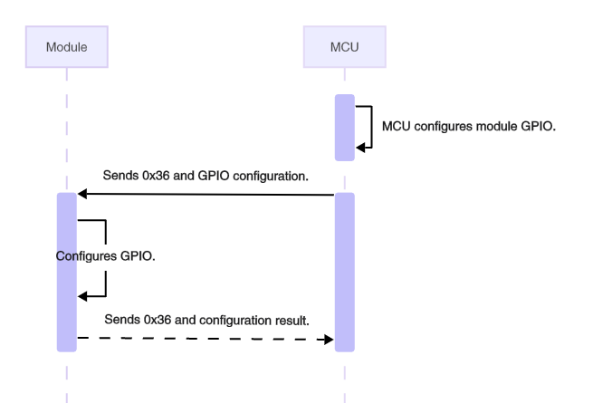
Configure GPIO pins (0x36)
Configure the GPIO mode for a module. The MCU can configure multiple modules simultaneously.
The MCU sends the following data.
| Field | Bytes | Description |
|---|---|---|
| Header | 2 | 0x55AA |
| Version | 1 | 0x02 |
| Seq. No. | 2 | xx xx |
| Command | 1 | 0x36 |
| Data length | 2 | N |
| Data | N | Number of GPIOs (1 byte) + GPIO configuration list |
| Checksum | 1 | xx |
- Number of GPIOs (1 byte): The number of GPIO pins to be configured.
- GPIO configuration list: Each GPIO configuration is four bytes, as shown below.
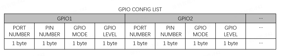
Example: 55 AA 02 xx xx 36 00 05 01 00 00 02 01 xx, configuring one GPIO named PA0, with GPIO_MODE_OUTPUT_PP and high-level output.
The module responds with the following data.
| Field | Bytes | Description |
|---|---|---|
| Header | 2 | 0x55AA |
| Version | 1 | 0x02 |
| Seq. No. | 2 | xx xx |
| Command | 1 | 0x36 |
| Data length | 2 | N |
| Data | N | Number of GPIOs (1 byte) + GPIO configuration result |
| Checksum | 1 | xx |
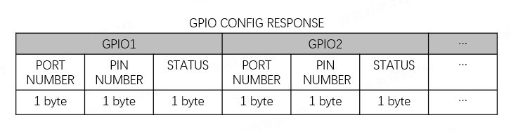
STATUS:0x00for configuration failure and0x01for configuration success.
Example: 55 AA 02 xx xx 36 00 05 01 00 00 02 01 xx
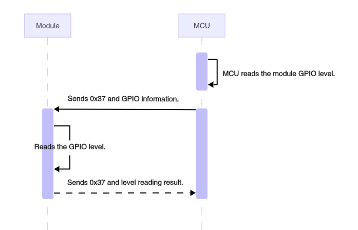
Read GPIO level (0x37)
Get the current level of the specified GPIO pin on the module. Before using this command, initialize the module’s GPIO pin through GPIO configuration.
The MCU sends the following data.
| Field | Bytes | Description |
|---|---|---|
| Header | 2 | 0x55AA |
| Version | 1 | 0x02 |
| Seq. No. | 2 | xx xx |
| Command | 1 | 0x37 |
| Data length | 2 | N |
| Data | N | Number of GPIOs (1 byte) + GPIO read list |
| Checksum | 1 | xx |
- Number of GPIOs (1 byte): The number of GPIO pins to be read.
- GPIO read list: Each GPIO is two bytes, as shown below.
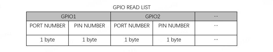
Example: 55 AA 02 xx xx 37 00 05 02 00 00 01 01 xx, reading the levels of PA0 and PB1.
The module responds with the following data.
| Field | Bytes | Description |
|---|---|---|
| Header | 2 | 0x55AA |
| Version | 1 | 0x02 |
| Seq. No. | 2 | xx xx |
| Command | 1 | 0x37 |
| Data length | 2 | N |
| Data | N | Number of GPIOs (1 byte) + GPIO level list |
| Checksum | 1 | xx |
- Number of GPIOs (1 byte): The number of GPIO pins to be read.
- GPIO level list: Each GPIO is three bytes, as shown below.
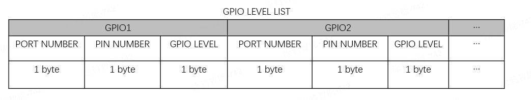
Example: 55 AA 02 xx xx 37 00 07 02 00 00 01 01 01 00 xx, indicating PA0 is high and PB1 is low.
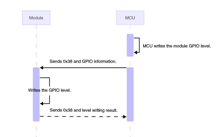
Control GPIO output (0x38)
When the module’s GPIO pin is configured as an output, use this command to set the output level to high or low.
The MCU sends the following data.
| Field | Bytes | Description |
|---|---|---|
| Header | 2 | 0x55AA |
| Version | 1 | 0x02 |
| Seq. No. | 2 | xx xx |
| Command | 1 | 0x38 |
| Data length | 2 | N |
| Data | N | Number of GPIOs (1 byte) + GPIO output control list |
| Checksum | 1 | xx |
- Number of GPIOs (1 byte): The number of GPIO pins to be set.
- GPIO output control list: Each GPIO is three bytes, as shown below.
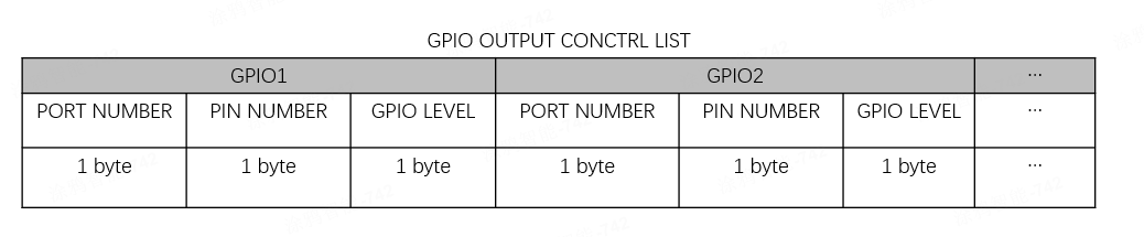
Example: 55 AA 02 xx xx 38 00 07 02 00 00 01 01 01 00 xx, indicating PA0 is set to output high and PB1 to output low.
The module responds with the following data.
| Field | Bytes | Description |
|---|---|---|
| Header | 2 | 0x55AA |
| Version | 1 | 0x02 |
| Seq. No. | 2 | xx xx |
| Command | 1 | 0x38 |
| Data length | 2 | N |
| Data | N | Number of GPIOs (1 byte) + GPIO output control response |
| Checksum | 1 | xx |
- Number of GPIOs (1 byte): The number of GPIO pins to be read.
- GPIO output control response: Each GPIO is three bytes, as shown below.
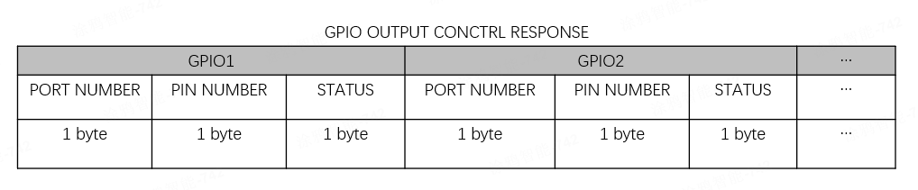
STATUS:0x00for success and0x01for failure.
Example: 55 AA 02 xx xx 38 00 07 02 00 00 00 01 01 00 xx, indicating PA0 outputs a high level while PB1 outputs a low level successfully.
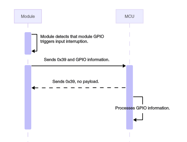
Sync GPIO input interrupt (0x39)
If the module’s GPIO pin is configured as an input interrupt, it notifies the MCU when a GPIO interrupt is detected.
The module sends the following data.
| Field | Bytes | Description |
|---|---|---|
| Header | 2 | 0x55AA |
| Version | 1 | 0x02 |
| Seq. No. | 2 | xx xx |
| Command | 1 | 0x39 |
| Data length | 2 | 0x0003 |
| Data | 3 | Port number (1 byte) + Pin number (1 byte) + GPIO level (1 byte) |
| Checksum | 1 | xx |
Example: 55 AA 02 xx xx 39 00 03 00 00 01 xx, indicating a PA0 interrupt is detected, triggered by a high-level signal.
The MCU responds with the following data.
| Field | Bytes | Description |
|---|---|---|
| Header | 2 | 0x55AA |
| Version | 1 | 0x02 |
| Seq. No. | 2 | xx xx |
| Command | 1 | 0x39 |
| Data length | 2 | 0x0000 |
| Data | 0 | None |
| Checksum | 1 | xx |
After the module notifies the MCU of a GPIO interrupt, it does not wait for a response from the MCU.
Initiate distributed linkage control
The distributed linkage feature shall be used with specific gateways and apps. For more information, consult the product manager.
Zigbee distributed linkage feature decentralizes linkage rules by storing them locally on Zigbee sub-devices instead of relying on cloud storage. After successful deployment, the system no longer relies on the Zigbee gateway or external networks to trigger linkages. This reduces dependency on both the gateway and cloud, significantly improving the stability of linkage triggers.
A device might act as a condition or an action. When a condition device triggers the linkage and its DP changes, the condition device will broadcast that its DP value has changed. When an action device receives this broadcast, it checks whether its locally stored linkage rules include the condition device’s specific DP, and whether the DP change has just satisfied the predefined condition. If the linkage rule conditions are met, the specified action will be triggered and executed.
For example, a distributed linkage rule is configured: When the contact sensor triggers and detects the presence of someone (DP1 = 1), the light turns on. When the contact sensor triggers locally (such as detecting someone), it broadcasts a command to the network, notifying other devices that its DP1 has changed to 1. If a connected light receives this command and confirms that the change satisfies its pre-configured linkage rule, it will execute the "turn on" action.
A standard network module can act as a condition or an action.
-
As an action: After receiving a message that meets the conditions in its linkage rules, the module will send a DP to notify the MCU.
-
As a condition: The MCU can configure (command
0x4A) which DP messages the module receives to broadcast its own DP value, or manually send0x4Bto enable or disable distributed linkage broadcast.
To ensure timely configuration delivery and reliable execution of distributed actions, if a low-power device is set as the execution device, it is recommended to configure its poll interval to 1 second or less.
Distributed linkage control (0x4A)
The MCU can proactively initiate distributed control commands to enable, disable, or trigger distributed linkage features of local devices.
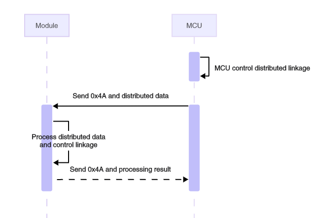
The MCU sends the following data.
| Field | Bytes | Description |
|---|---|---|
| Header | 2 | 0x55AA |
| Version | 1 | 0x02 |
| Sequence number | 2 | xx xx |
| Command | 1 | 0x4A |
| Data length | 2 | 0x0006 |
| Data | 5 | Refer to the distributed data content format. |
| Checksum | 1 | xx |
Distributed data content format
| Name | Data type | Description |
|---|---|---|
| action | UINT8_T | 0x00: Disable 0x01: Enable 0x02: Execute |
| auto id | UINT16_T | The ID of the specified distributed linkage. The ID is sent by the gateway in the form of DPs. |
| loopback | UINT8_T | Whether to loopback 0x00: Disable 0x01: Enable |
| delay time | UINT16_T | The delay time. Unit: milliseconds. |
The module responds with the following data.
| Field | Bytes | Description |
|---|---|---|
| Header | 2 | 0x55AA |
| Version | 1 | 0x02 |
| Sequence number | 2 | xx xx |
| Command | 1 | 0x4A |
| Data length | 2 | 0x0001 |
| Data | 1 | 0x00: success. 0x01: failure. |
| Checksum | 1 | xx |
Configure distributed linkage broadcast DP (0x4B)
The MCU can configure which of its own DPs trigger distributed DP broadcasts when reporting a message (0x06). When an action device with pre-configured linkage rules receives this broadcast, it checks whether its locally stored linkage rules include this DP. If the stored linkage rules include this DP and the DP change meets the rule’s condition, the corresponding action in the linkage rule will be triggered and run.
- Support up to 8 DPs for broadcasting.
- Each new DP list overwrites the previous list (no appending). This list is stored in flash memory and does not need to be reconfigured on reboot.
- Currently, only DP types bool, enum, and value are supported.
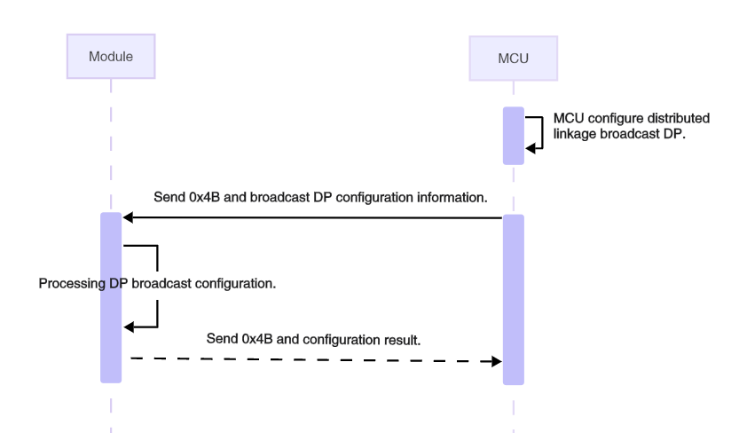
The MCU sends the following data.
| Field | Bytes | Description |
|---|---|---|
| Header | 2 | 0x55AA |
| Version | 1 | 0x02 |
| Sequence number | 2 | xx xx |
| Command | 1 | 0x4B |
| Data length | 2 | N |
| Data | N | Refer to the broadcast DP configuration |
| Checksum | 1 | xx |
Broadcast DP configuration
| Name | Data type | Description |
|---|---|---|
| Enable | BOOL_T | Specifies whether to enable the distributed broadcast feature. 0x00: Disable 0x01: Enable |
| Number of DPs | UINT8_T | The number of broadcast DPs. |
| DP ID 1 | UINT8_T | The ID of a DP. |
| … | … | … |
| DP ID N | UINT8_T | The ID of a DP. N ≤ 8. |
The module returns the following data.
| Field | Bytes | Description |
|---|---|---|
| Header | 2 | 0x55AA |
| Version | 1 | 0x02 |
| Sequence number | 2 | xx xx |
| Command | 1 | 0x4B |
| Data length | 2 | 0x0001 |
| Data | 1 | 0x00: success. 0x01: failure. |
| Checksum | 1 | xx |
Time and weather
Sync time (0x24)
Some devices require the current time to implement features such as local schedules or information displays. The device can request time information from the gateway, which responds with the data after time zone conversion. After receiving the time sync command from the MCU, the module sends a time request to the gateway and relays the response back to the MCU.
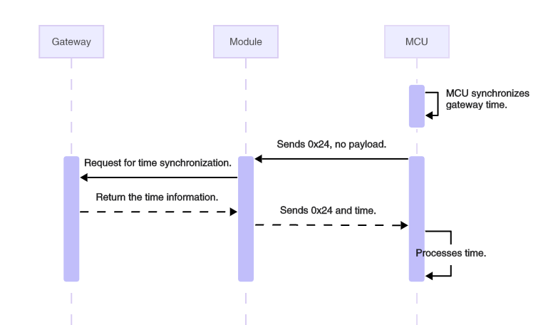
The MCU sends the following data.
| Field | Bytes | Description |
|---|---|---|
| Header | 2 | 0x55AA |
| Version | 1 | 0x02 |
| Seq. No. | 2 | xx xx |
| Command | 1 | 0x24 |
| Data length | 2 | 0x0000 |
| Data | 0 | None |
| Checksum | 1 | xx |
Example: 55 AA 02 xx xx 24 00 00 xx, indicating the MCU initiates a time sync request.
The module responds with the following data.
| Field | Bytes | Description |
|---|---|---|
| Header | 2 | 0x55AA |
| Version | 1 | 0x02 |
| Seq. No. | 2 | xx xx |
| Command | 1 | 0x24 |
| Data length | 2 | 0x0008 |
| Data | 8 | Unix timestamp (4 bytes) + local timestamp (4 bytes) |
| Checksum | 1 | xx |
- Unix timestamp: The number of seconds that have elapsed since January 1, 1970, at 00:00:00 Greenwich Mean Time (GMT).
- Local timestamp: Calculated by adding the time zone offset and daylight saving time (DST) (if applicable) to the Unix timestamp. Local time typically prevails.
Example: 55 AA 02 xx xx 24 00 08 66 45 DB F0 66 46 4C 70 xx
- Unix time:
0x6645DBF0 - Local time:
0x66464C70
Request weather information (0x3A)
Some devices require the weather data to implement features such as information displays. They can request weather information from a gateway, which retrieves it from the internet and responds accordingly. After receiving the weather information request from the MCU, the module forwards it to the gateway. After the gateway responds, the module notifies the MCU with the command Sync Weather Information.
Weather information is categorized into two types based on time.
- Current weather: The current weather conditions retrieved from the cloud, including temperature, humidity, wind direction, and wind speed.
- Weather forecast: The weather forecast for up to seven days, including today.
Weather information is categorized into two types based on location.
- Gateway location: The weather in the location where the gateway is activated prevails. If the gateway activation location is the same as the current gateway location, it is also the device’s current location.
- Home location on app: The weather in the location specified for the home in the Tuya-enabled mobile app prevails.
Weather data content:
- Weather data: Various types of weather data are represented by weather IDs, for example, 01 for temperature, 02 for humidity, and 03 for weather overview. See Appendix 1: Weather data.
- City name: The name of the current city in string, used for information display.
- The weather command currently applies only to specific module firmware, with more modules expected to be supported in the future. Before use, check if your module supports this command.
- Weather data and city names should be requested separately.
- It is recommended that the weather command be requested at intervals of one hour.
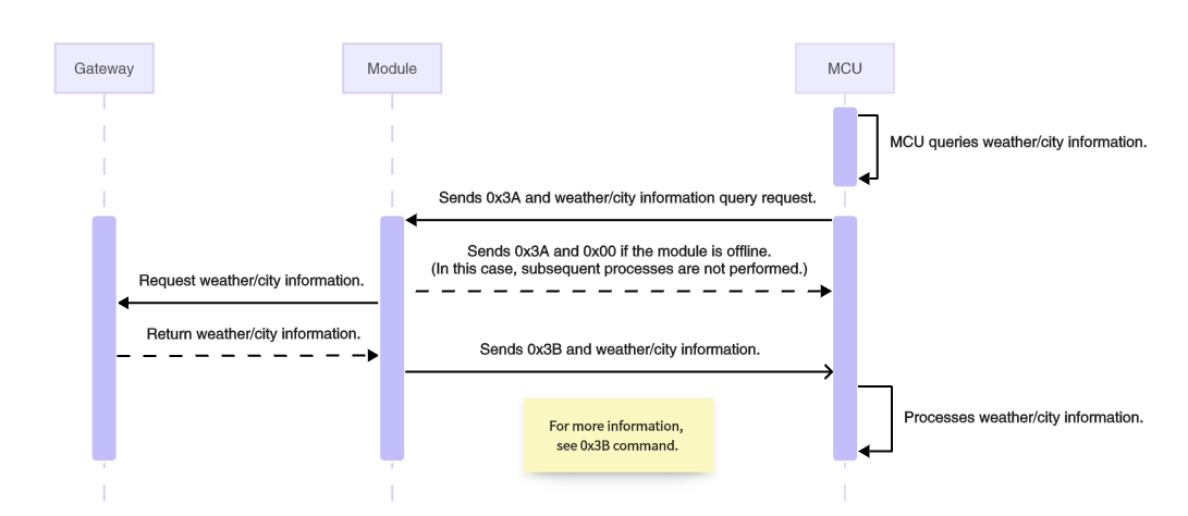
The MCU sends the following data.
| Field | Bytes | Description |
|---|---|---|
| Header | 2 | 0x55AA |
| Version | 1 | 0x02 |
| Seq. No. | 2 | xx xx |
| Command | 1 | 0x3A |
| Data length | 2 | N |
| Data | N | The format for weather and city name request |
| Checksum | 1 | xx |
Weather request format
| Field | Bytes | Description |
|---|---|---|
| Version number | 1 | Fixed to 0x12 |
| Location type | 1 | 0x00: The device's location. The gateway activation location prevails. 0x01: Home location on the app. |
| Weather ID | N | The weather parameter to request, each with a unique ID (1 byte). At least one weather ID is requested. |
| Weather forecast flag | 1 | Fixed to 0x12, also serving as the end marker for weather IDs. |
| Number of forecast days | 1 | Valid values range from 1 to 7. You can request the weather forecast for up to seven days, including today. |
| Current weather flag | 1 | Fixed to 0x13 |
| Whether to support current weather | 1 | 0x00: Not Support. 0x01: Support. |
- The weather forecast flag and number of forecast days are optional. If the weather forecast is not needed, these two fields should be excluded.
- The Current Weather Flag must be present. A state where neither current weather data nor forecast data is included must not occur.
City name request format
| Field | Bytes | Description |
|---|---|---|
| Version number | 1 | Fixed to 0x12 |
| Location type | 1 | 0x00: The device's location. The gateway activation location prevails. 0x01: Home location on the app. |
| District or county request flag | 6 | 0x63 0x2E 0x61 0x72 0x65 0x61 corresponding to c.area |
| City request flag | 6 | 0x63 0x2E 0x63 0x69 0x74 0x79 corresponding to c.city |
Example 1: 55 AA 02 xx xx 3A 00 07 12 00 01 02 03 13 01 xx
12: The version number.00: Use the device’s location.01 02 03: The weather IDs to request, including01(temperature),02(humidity), and03(weather overview).13: Whether to support the current weather.01: Support the current weather.
This example requests the current weather conditions including temperate, humidity, and weather overview in the device’s location, without weather forecasts.
Example 2: 55 AA 02 xx xx 3A 00 09 12 00 01 02 03 12 07 13 00 xx
12: The version number.00: Use the device’s location.01 02 03: The weather IDs to request, including01(temperature),02(humidity), and03(weather overview).12: The weather forecast flag.07: Request weather forecasts for seven days, including today.13: Whether to support the current weather.00: Not support the current weather.
This example requests the weather forecasts for seven days, including temperate, humidity, and weather overview in the device’s location, without the current weather.
Example 3: 55 AA 02 xx xx 3A 00 0D 12 00 63 2E 61 72 65 61 63 2E 63 69 74 xx, requesting the names of the city and district or county where the device is located.
12: The version number.00: Use the device’s location.63 2E 61 72 65 61: The name of the requested district or county.63 2E 63 69 74 79: The name of the requested city.
The module returns the following data.
- If the module is unpaired or the gateway response times out, the module returns a failure.
- If the module is paired and the gateway responds with weather information, the module notifies the MCU with the command Sync Weather Information.
Sync weather information (0x3B)
The module sends the received weather information from the gateway to the MCU. The weather information from the gateway is sourced from the internet.
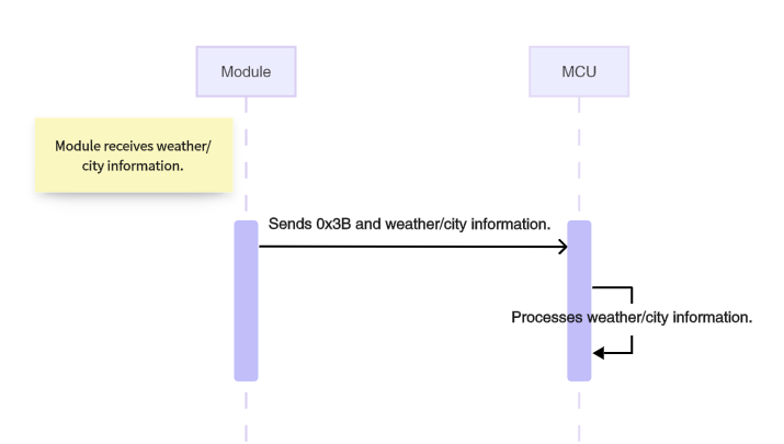
The module sends the following data.
| Field | Bytes | Description |
|---|---|---|
| Header | 2 | 0x55AA |
| Version | 1 | 0x02 |
| Seq. No. | 2 | xx xx |
| Command | 1 | 0x3B |
| Data length | 2 | N |
| Data | N | The format for weather data or city information |
| Checksum | 1 | xx |
Weather data format
| Field | Bytes | Description |
|---|---|---|
| Version number | 1 | Fixed to 0x12 |
| Location type | 1 | 0x00: The device's location. The gateway activation location prevails. 0x01: Home location on the app. |
| Weather forecast flag | 1 | Fixed to 0x12 |
| Number of forecast days | 1 | 0x00: Weather forecast excluded. n (0x01 to 0x07): Weather forecast included. |
| Current weather flag | 1 | Fixed to 0x13 |
| Current weather | 1 | 0x00: Current weather excluded. 0x01: Current weather included. |
| Weather information | N | Weather parameter 1 + weather parameter 2… |
Weather parameters format: weather ID + current weather + today’s forecast + tomorrow’s forecast + the day after tomorrow’s forecast… (depending on the number of forecast days)
- Weather ID: See Appendix 1: Weather data.
- Current weather: This field is included when Current Weather is set to 1, and its length varies based on the weather ID.
- Weather forecast: This field is included when the number of forecast days is greater than 0. The number of data sets corresponds to the number of forecast days.
Example payload of the frame:
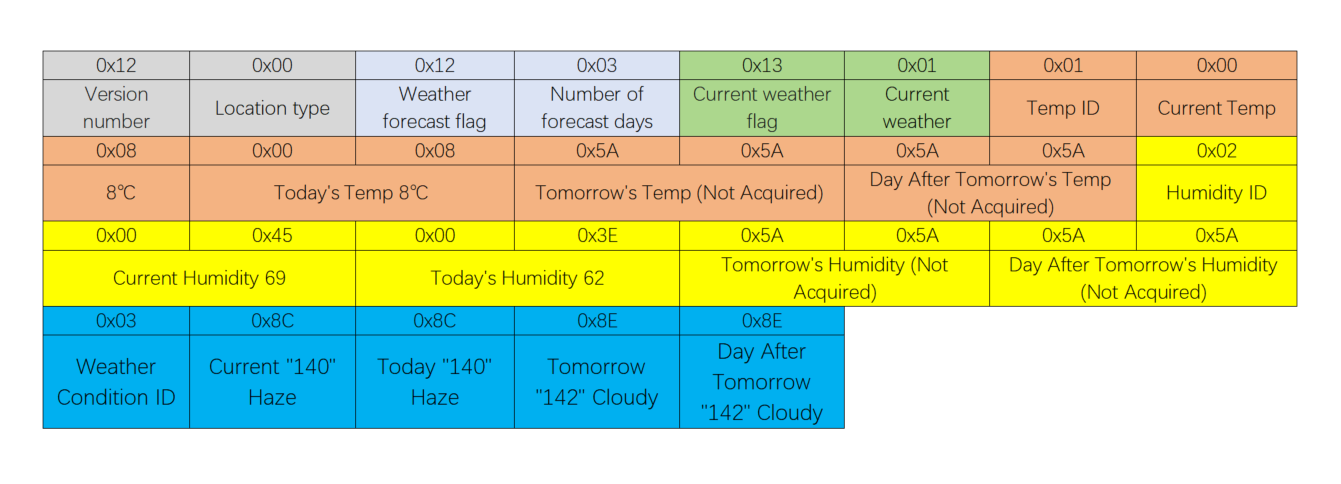
This example only shows the weather data format.
- Location type:
0x00, indicating the device’s location prevails. - Number of forecast days:
0x03, including weather forecasts for three days. - Current weather:
0x01, indicating the current weather conditions are included. - Each weather parameter includes four sets of data, with the content organized as follows: current weather, today’s forecast, tomorrow’s forecast, and the day after tomorrow’s forecast.
-
Negative numbers are represented in two’s complement form, e.g., sub-zero temperatures.
-
If certain information cannot be acquired, weather data fields are filled with the default value '0x5A', and city data fields with '0xFF'.
-
Weather Protocol v1.2 requires the gateway to be upgraded to the latest firmware version. Wired gateways do not support v1.2 at this time. If you need to continue using Weather Protocol v1.1, set the requested version field to 0x11 in v1.1 requests. In v1.1 responses, invalid values will be padded with 0xFF. For further details, please contact the product manager.
City information format
| Field | Bytes | Description |
|---|---|---|
| Version number | 1 | Fixed to 0x12 |
| Location type | 1 | 0x00: The device's location. The gateway activation location prevails. 0x01: Home location on the app. |
| District or county flag | 6 | 0x63 0x2E 0x61 0x72 0x65 0x61 corresponding to c.area |
| District or county name | N | Variable length, up to 24 bytes. |
| City flag | 6 | 0x63 0x2E 0x63 0x69 0x74 0x79 corresponding to c.city |
| City name | N | Variable length, up to 24 bytes. |
Example: 0x12 01 63 2E 61 72 65 61 E8 A5 BF E6 B9 96 E5 8C BA 63 2E 63 69 74 79 E6 9D AD E5 B7 9E
12: The version number, a fixed value.01: The location type is01, indicating the home location on the app prevails.63 2E 61 72 65 61:c.area, followed by the name of the district or county.E8 A5 BF E6 B9 96 E5 8C BA: Xihu District63 2E 63 69 74 79:c.city, followed by the name of the city.E6 9D AD E5 B7 9E: Hangzhou
The MCU responds with the following data.
The module does not wait for a response from the MCU.
Appendix
Appendix 1: Weather data
| Weather ID | Field | Meaning | Type | Description |
|---|---|---|---|---|
| 1 | Temperature | Atmospheric temperature | INT16 | 7-day forecast (except for mainland China) |
| 2 | Humidity | Air humidity | UINT16 | 7-day forecast |
| 3 | ConditionNum | Weather condition No. | UINT8 | 7-day forecast |
| 4 | RealFeel | Apparent temperature | UINT16 | N/A |
| 5 | uvi | Ultraviolet index | UINT8 | 7-day forecast |
| 6 | windSpeed | Wind speed | UINT8 | 7-day forecast. The value is the actual wind speed multiplied by 10. Divide it by 10 to get the actual wind speed. |
| 7 | windDir | Wind direction | UINT8 | 7-day forecast |
| 8 | windLevel | Wind scale | UINT8 | 7-day forecast |
| 9 | aqi | Air quality index | UINT16 | Current day only |
| 10 | Pm10 | PM10 | UINT16 | Current day only |
| 11 | Pm25 | PM2.5 | UINT16 | Current day only |
| 12 | O3 | Ozone level | UINT16 | Current day only |
| 13 | No2 | Nitrogen dioxide level | UINT16 | Current day only |
| 14 | Co | Carbon monoxide level | UINT16 | Current day only |
| 15 | So2 | Sulfur dioxide level | UINT16 | Current day only |
| 16 | T-high | The highest temperature | INT16 | Forecast only |
| 17 | T-low | The lowest temperature | INT16 | Forecast only |
| 18 | Data | Number of forecast days | UINT8 | 1 ≤ n ≤ 7. This field applies when only when the weather forecast is supported. |
| 19 | Currdate | Current weather | Boolean | 1: Current weather included. 0: Current weather excluded. |
Appendix 2: Weather data in UTF-8 encoding
| Weather ID | Code | Hexadecimal value | Description |
|---|---|---|---|
| 0x78 | 120 | 31 32 30 | Sunny |
| 0x65 | 101 | 31 30 31 | Heavy rain |
| 0x66 | 102 | 31 30 32 | Thunderstorm |
| 0x67 | 103 | 31 30 33 | Sandstorm |
| 0x68 | 104 | 31 30 34 | Light snow |
| 0x69 | 105 | 31 30 35 | Snow |
| 0x6a | 106 | 31 30 36 | Freezing fog |
| 0x6b | 107 | 31 30 37 | Rainstorm |
| 0x6c | 108 | 31 30 38 | Isolated shower |
| 0x6d | 109 | 31 30 39 | Dust |
| 0x6e | 110 | 31 31 30 | Thunder and lightning |
| 0x6f | 111 | 31 31 31 | Light shower |
| 0x70 | 112 | 31 31 32 | Rain |
| 0x71 | 113 | 31 31 33 | Sleet |
| 0x72 | 114 | 31 31 34 | Dust devil |
| 0x73 | 115 | 31 31 35 | Ice pellet |
| 0x74 | 116 | 31 31 36 | Strong sandstorm |
| 0x75 | 117 | 31 31 37 | Sand blowing |
| 0x76 | 118 | 31 31 38 | Light to moderate rain |
| 0x77 | 119 | 31 31 39 | Mostly clear |
| 0x79 | 121 | 31 32 31 | Fog |
| 0x7a | 122 | 31 32 32 | Shower |
| 0x7b | 123 | 31 32 33 | Heavy shower |
| 0x7c | 124 | 31 32 34 | Heavy snow |
| 0x7d | 125 | 31 32 35 | Extrodinary rainstorm |
| 0x7e | 126 | 31 32 36 | Blizzard |
| 0x7f | 127 | 31 32 37 | Hail |
| 0x80 | 128 | 31 32 38 | Light to moderate snow |
| 0x81 | 129 | 31 32 39 | Partly cloudy |
| 0x82 | 130 | 31 33 30 | Light snow shower |
| 0x83 | 131 | 31 33 31 | Moderate snow |
| 0x84 | 132 | 31 33 32 | Overcast |
| 0x85 | 133 | 31 33 33 | Needle ice |
| 0x86 | 134 | 31 33 34 | Downpour |
| 0x88 | 136 | 31 33 36 | Thundershower and hail |
| 0x89 | 137 | 31 33 37 | Freezing rain |
| 0x8a | 138 | 31 33 38 | Snow shower |
| 0x8b | 139 | 31 33 39 | Light rain |
| 0x8c | 140 | 31 34 30 | Haze |
| 0x8d | 141 | 31 34 31 | Moderate rain |
| 0x8e | 142 | 31 34 32 | Cloudy |
| 0x8f | 143 | 31 34 33 | Thundershower |
| 0x90 | 144 | 31 34 34 | Moderate to heavy rain |
| 0x91 | 145 | 31 34 35 | Heavy rain to rainstorm |
| 0x92 | 146 | 31 34 36 | Clear |
Appendix 3: Wind direction code
| Wind ID | Code (string) | Description |
|---|---|---|
| 0x00 | N | North |
| 0x01 | NNE | Northeast by north |
| 0x02 | NE | Northeast |
| 0x03 | ENE | Northeast by east |
| 0x04 | E | East |
| 0x05 | ESE | Southeast by east |
| 0x06 | SE | Southeast |
| 0x07 | SSE | Southeast by south |
| 0x08 | S | South |
| 0x09 | SSW | Southwest by south |
| 0x0a | SW | Southwest |
| 0x0b | WSW | Southwest by west |
| 0x0c | W | West |
| 0x0d | WNW | Northwest by west |
| 0x0e | NW | Northwest |
| 0x0f | NNW | Northwest by north |
Version history
| Changes | Revision date | Description |
|---|---|---|
| Optimized | April 2, 2026 | 1. Updated the UART pin-group mapping and auto-adaptation polling mechanism for ZT series modules. 2. Optimized the accuracy of the command text. |
| Optimized | January 30, 2026 | 1. Optimized the UART command timing diagram. 2. Updated Weather Protocol to version 1.2. 3. Added usage instructions for Dongle production testing with command 0x21. 4. Added recommendations for GPIO configuration and distributed linkage functionality. |
| Optimized | September 26, 2025 | 1. Correct the description of the response frame for the 0x0A command module. 2. Correct the description of the distributed data content format for the 0x4A command. 3. Correct the description of the weather request format for the 0x3A command. 4. Correct the description of the pin for waking up the MCU by the ZSC module. |
| Added commands | May 22, 2025 | 1. Added distributed linkage control, using the 0x4A command. 2. Added distributed linkage broadcast DP configuration, using the 0x4B command. 3. Added optional s and lp key values and their function descriptions in the product information. 4. Optimized the accuracy of the command text. |
| Optimized | December 3, 2024 | 1. Updated the weather data in UTF-8 coding in Appendix 2. |
| Optimized | November 22, 2024 | 1. Fixed the product information example of the 0x01 command. |
| Added commands | November 12, 2024 | 1. Added the 0x07 command for getting module information.2. Added the 0x21 and 0x22 commands for performing Dongle production test.3. Added sequence diagrams. 4. Optimized the accuracy of the command text. |
| Optimized | July 25, 2024 | 1. Added the MCU response description for command 0x0C. |
| Optimized | July 17, 2024 | 1. Revised the maximum transmission unit for the command 0x0D.2. Optimized the accuracy of the command text. |
| Optimized | July 8, 2024 | Optimized the document format and improved the command descriptions. |
| Added commands | May 21, 2024 | 1. Added 0x2C for the linkage filter. 2. Added 0x36, 0x37, 0x38, and 0x39 for GPIO configurations. 3. Added 0x3A and 0x3B for weather request. |
| Optimized | November 14, 2022 | Optimized the document format and improved the command descriptions. |
| Added commands | September 2, 2022 | Added the gateway network status query by the MCU. |
| Added commands | August 17, 2022 | 1. Added the commands 0x2A, 0x2B, 0x41, 0x42, and 0x43. 2. Added the option to set the transmit power of mains-powered devices. 3. Added the optional field g in the product information. |
| Optimized | March 22, 2022 | Modified the description of auto-baud detection. |
| Added commands | December 14, 2021 | Added remote factory reset notification, Zigbee network policy configuration, MCU broadcasting messages, and reading DP data. |
| Optimized | November 18, 2020 | 1. Specified that voltage level or pulse is used to wake up the module and the MCU. 2. Specified that the rejoining duration refers to the accumulation of failed attempts. |
| Added commands | August 1, 2020 | 1. Added fields to MCU type query. 2. Added fields to network policy configuration. |
| Optimized | July 15, 2020 | 1. Specified the range of sequence numbers. 2. Modified the data length to 62 bytes. 3. Specified that the channel for testing defaults to channel 11. 4. Added protocol descriptions. |
| Reorganized | February 4, 2020 | Added logic for indicating pairing status. |
| Modified | October 29, 2018 | 1. Added reliable data transmission. 2. Added wake-up mechanism for low power devices. |
| Modified | July 31, 2018 | Added protocols for scene switches. |
| Modified | July 2, 2018 | 1. Added passive data reporting and retransmission mechanism. 2. Added hardware handshaking. |
| Modified | June 28, 2018 | 1. Modified the timeout period. 2. Modified the passive reporting method. 3. Modified the module configuration method. |
| Creation | June 23, 2018 | Creation |
Is this page helpful?
YesFeedbackIs this page helpful?
YesFeedback


