MCU SDK Porting
Overview
MCU SDK is a set of MCU codes automatically generated according to the product functions defined on the Tuya Developer Platform, facilitating MCU program development. This topic describes the process and notes to port the MCU SDK to Zigbee devices.
Code framework
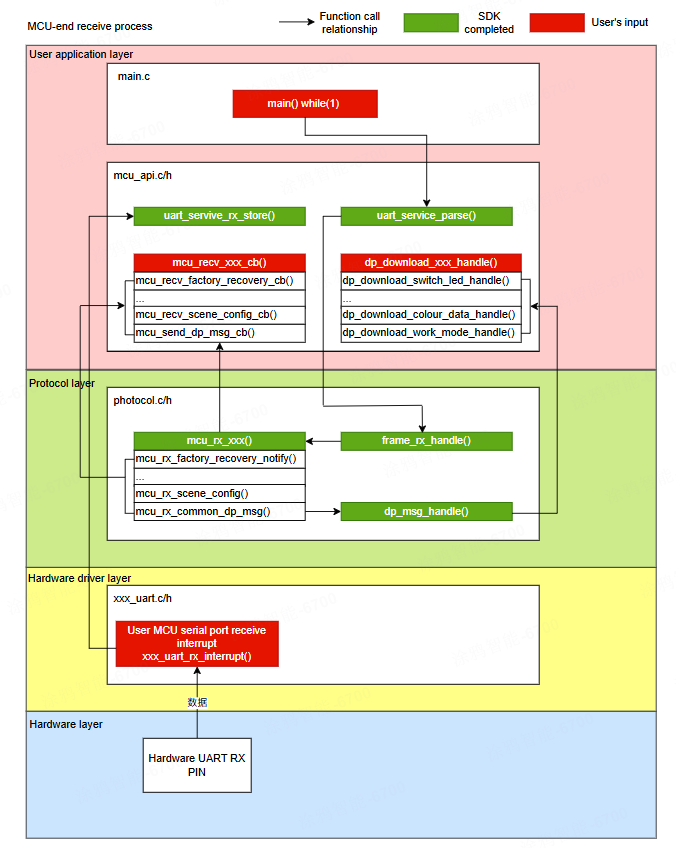
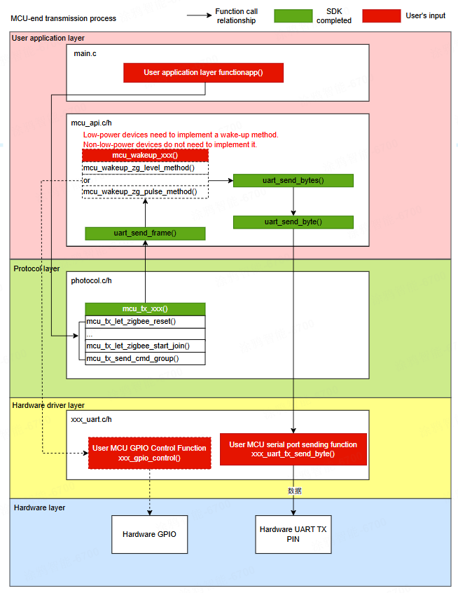
Developers are requested to focus on the red-highlighted sections, and the relevant functions need to be implemented independently.
File structure
Before porting the MCU SDK, you need to download the SDK source code. For more information, see the MCU low-code development. After downloading, the MCU SDK consists of the following files:
| File | Description |
|---|---|
zigbee.h |
Defines general macros. |
system.h |
system.h contains the following information:
|
system.c |
system.c contains the following information:
|
protocol.h |
protocol.h contains the following information:
|
protocol.c |
protocol.c contains the following information:
|
mcu_api.h |
mcu_api.h contains the following information:
|
mcu_api.c |
mcu_api.c contains the following information:
|
mcu_sdk_types.h |
mcu_sdk_types.h contains the following information:
|
During development, it is crucial to focus on the mcu_api.h and mcu_api.c files, as the sections of code that require manual modification are located within these interface files. Additionally, you need to review and modify the protocol.h and protocol.c files as needed, which are related to configurations on the Tuya Developer Platform.
How to port SDK
Follow the porting process outlined below.
- Implement MCU platform peripheral functionalities.
- Port SDK source files.
- Modify interface files.
- Configure parameters.
- Modify protocol files.
Step 1: Implement peripheral functionalities
Before officially porting the MCU SDK, you need to implement at least the following peripheral functionalities on your own MCU platform.
- UART serial port: Functionality for transmitting and receiving communication data with the module.
- Timer: Timing functionality.
- GPIO: Functionality to control module wake-up and to be woken up itself.
Step 2: Port SDK source files
Add the .c and .h files in the MCU SDK folder to the corresponding reference path of the source file and header file of your project.
Step 3: Modify interface files
Modify the interface files mcu_api.h and mcu_api.c, which are primarily divided into four parts:
Part 1: Process UART receive data
You need to feed the data received by the MCU’s UART, byte by byte, into the uart_servive_rx_store() function. Then, periodically call the uart_service_parse() function (either in the main loop or via a timer interrupt).
void USART1_IRQHandler(void)
{
    uint8_t data;

    if (USART_GetITStatus(USART1, USART_IT_RXNE) != RESET)
    {
        data = USART_ReceiveData(USART1);
        void uart_servive_rx_store(unsigned char value);
        uart_servive_rx_store(data);
        USART_ClearITPendingBit(USART1, USART_IT_RXNE);
    }
}

int main(void)
{
    app_uart_init();
    MAIN_DEBUG(" mcu sdk example ");

    while(1)
    {
        uart_service_parse();
    }
}
Part 2: Confirm wake-up method
Confirm whether you are developing a low power device. The configuration macros in the interface files are as follows:
///< <USER MUST NOT CHANGE>
#define ROUTER_DEVICE                           1
#define SLEEP_END_DEVICE                        2
#define SCENE_SWITCH_DEVICE                     3

#define LOW_LEVEL_WAKE_UP                       1
#define LOW_PULSE_WAKE_UP                       2
///< END <USER MUST NOT CHANGE>

///< <USER MUST CHECK AND CHANGE>
#define MCU_VER                                 "1.0.0"
#define DEVICE_TYPE                             ROUTER_DEVICE
#if (DEVICE_TYPE == SLEEP_END_DEVICE)
#define MCU_WAKEUP_MODULE_METHOD                LOW_LEVEL_WAKE_UP
#endif
///< END <USER MUST CHECK AND CHANGE>
If you are developing a non-low power device (DEVICE_TYPE = ROUTER_DEVICE or DEVICE_TYPE = SCENE_SWITCH_DEVICE), you can skip this section directly.
If you are developing a low power device (DEVICE_TYPE = SLEEP_END_DEVICE), you need to select a wake-up method. The basic implementation flow is as follows. For more information, refer to Low power wake-up in the protocol. You need to integrate the implementation of waiting and timeout logic with your own MCU platform’s timers, GPIO, and other peripherals.
To be added
Part 3: UART transmit data
Implement the single-byte UART transmit functionality within the definition of the uart_send_bytes() function.
void uart_send_byte(unsigned char value)
{
    void app_uart_send_byte(unsigned char data);
    app_uart_send_byte(value);
}

void uart_send_bytes(unsigned char *data, unsigned short data_len)
{
    if ((NULL == data)) {
        return;
    }

    for (unsigned short i = 0; i < data_len; i++) {
        uart_send_byte(data[i]);
    }
}
Part 4: Implement receive frame parsing callbacks
The MCU SDK has already reserved callback interfaces for processing specific commands after protocol parsing. You can populate these functions as needed. The specific interfaces are as follows:
void mcu_recv_factory_recovery_cb(void)
{
    //< USER TODO
}
  . . .
  . . .

  Omit

  . . .
  . . .
void mcu_recv_gw_nwk_status_cb(unsigned char nwk_status)
{
    //< USER TODO
}
Step 4: Configure parameters
Additionally, you can choose to modify some other macro definitions:
| Macro definition | Description | Notes |
|---|---|---|
| MCU_VER | MCU firmware version | The MCU software version defaults to 1.0.0. If the MCU requires OTA functionality, the MCU must be changed to a new version number each time the MCU firmware is updated. |
| DEVICE_TYPE | Device type | Must select one of the following:
|
| MCU_WAKEUP_MODULE_METHOD | MCU wake-up method for low power devices | Must select one of the following:
|
| SUPPORT_RECEIVE_BROADCAST_DATA | Whether the MCU receives broadcast messages | Default: 0x01
|
| ZG_WAIT_MCU_TIME_DEFAULT | The time the Zigbee device waits for the MCU’s serial communication function to be ready after waking up the MCU | Default: 10 ms |
| MCU_WAIT_ZG_TIME_DEFAULT | The time the MCU waits for the Zigbee device’s serial communication function to be ready after waking up the Zigbee device | Default: 10 ms |
| UART_RX_BUF_LEN_LMT | UART receive buffer array size | Default: 256Can be reduced as needed |
| UART_TX_BUF_LEN_LMT | UART transmit buffer array size | Default: 256Can be reduced as needed |
| UART_QUEUE_BUF_LEN_LMT | UART receive queue size | Default: 512Can be reduced as needed |
| OTA_PACKET_SIZE | Single OTA packet size | Default: 0x30Maximum: 0x30, can be reduced as needed |
| MCU_SDK_DEBUG PRINT_DEBUG(fmt, …) |
Log interfaces | Default: Disabled Can be enabled after configuring the print function as needed |
Step 5: Modify protocol files
The files protocol.h and protocol.c are automatically generated by configuring data points (DPs) on the Tuya Developer Platform. You need to verify the following points to ensure they match your expected DP information (you can perform a global search in the code for USER_CHECK_MSG). Below are specific code examples for reference. Please note that actual scenarios should be determined based on your configuration.
Check PID
//< USER_CHECK_MSG
///<product key(pid)  the same as yours in the Tuya Developer Platform

#define PRODUCT_KEY "xn7xzluu"    // A 16-bit unique identifier of a product that is generated after the product is created on Tuya Developer Platform.

//< USER_CHECK_MSG END
Check DP ID macro definition
//< USER_CHECK_MSG
///< dp id define
// Switch 1 (Send and report)
// Notes:
#define DPID_SWITCH_1 1

. . .

Omit

. . .

// Random timing (Send and report)
// Notes: #1 Protocol version
///#2 Node length
///#3 Channel number (bit0: switch. bit1-bit7: channel number)
///#4 Day of the week
///#5#6 Start time (minutes)
///#7#8 End time (minutes)
#define DPID_RANDOM_TIMING 210

//< USER_CHECK_MSG END
Check DP ID commands
//< USER_CHECK_MSG
/*----------------------------------------------------------
 *                        DP list
 * 1. please check the ID and type of each DP.
 *--------------------------------------------------------*/
const DOWNLOAD_CMD_S download_cmd[] =
{
  {DPID_SWITCH_1, DP_TYPE_BOOL},
  {DPID_SWITCH_2, DP_TYPE_BOOL},
  {DPID_SWITCH_3, DP_TYPE_BOOL},
  {DPID_SWITCH_4, DP_TYPE_BOOL},
  {DPID_SWITCH_5, DP_TYPE_BOOL},
  {DPID_SWITCH_6, DP_TYPE_BOOL},
  {DPID_COUNTDOWN_1, DP_TYPE_VALUE},
  {DPID_COUNTDOWN_2, DP_TYPE_VALUE},
  {DPID_COUNTDOWN_3, DP_TYPE_VALUE},
  {DPID_COUNTDOWN_4, DP_TYPE_VALUE},
  {DPID_COUNTDOWN_5, DP_TYPE_VALUE},
  {DPID_COUNTDOWN_6, DP_TYPE_VALUE},
  {DPID_SWITCH_ALL, DP_TYPE_BOOL},
  {DPID_RELAY_STATUS, DP_TYPE_ENUM},
  {DPID_LIGHT_MODE, DP_TYPE_ENUM},
  {DPID_BACKLIGHT_SWITCH, DP_TYPE_BOOL},
  {DPID_SWITCH_INCHING, DP_TYPE_STRING},
  {DPID_ADD_ELE, DP_TYPE_VALUE},
  {DPID_CUR_CURRENT, DP_TYPE_VALUE},
  {DPID_CUR_POWER, DP_TYPE_VALUE},
  {DPID_CUR_VOLTAGE, DP_TYPE_VALUE},
  {DPID_TEST_BIT, DP_TYPE_VALUE},
  {DPID_VOLTAGE_COE, DP_TYPE_VALUE},
  {DPID_ELECTRIC_COE, DP_TYPE_VALUE},
  {DPID_POWER_COE, DP_TYPE_VALUE},
  {DPID_ELECTRICITY_COE, DP_TYPE_VALUE},
  {DPID_RELAY_STATUS_1, DP_TYPE_ENUM},
  {DPID_RELAY_STATUS_2, DP_TYPE_ENUM},
  {DPID_RELAY_STATUS_3, DP_TYPE_ENUM},
  {DPID_RELAY_STATUS_4, DP_TYPE_ENUM},
  {DPID_RELAY_STATUS_5, DP_TYPE_ENUM},
  {DPID_RELAY_STATUS_6, DP_TYPE_ENUM},
  {DPID_CYCLE_TIMING, DP_TYPE_RAW},
  {DPID_RANDOM_TIMING, DP_TYPE_RAW},
};

//< USER_CHECK_MSG END
Send DP messages
Confirm whether each sent DP needs to perform a corresponding operation. If you want to implement this logic yourself, pay special attention within the dp_msg_handle() function to the handler function corresponding to each case branch. For example, for switch 1 messages, focus on the dp_download_switch_1_handle() function. Other scenarios can be handled similarly.
/*****************************************************************************
Function name: dp_download_switch_1_handle
Description: Handler function for DPID_SWITCH_1
Input parameters: value indicates the data source
                   length indicates data length
Return parameters: Return SUCCESS on success and ERROR on failure
Instruction: Regarding the data for reporting and sending, the processing results must be reported to the app after processing
*****************************************************************************/
static unsigned char dp_download_switch_1_handle(const unsigned char value[], unsigned short length)
{
    // Example: The current DP type is Boolean.
    unsigned char ret;
    //0:off/1:on
    unsigned char switch_1;

    switch_1 = mcu_get_dp_download_bool(value,length);
    if(switch_1 == 0) {
        //bool off
    }else {
        //bool on
    }

    //There should be a report after processing the DP
    ret = mcu_dp_bool_update(DPID_SWITCH_1,switch_1);
    if(ret == SUCCESS)
        return SUCCESS;
    else
        return ERROR;
}

//< USER_CHECK_MSG END
static unsigned char dp_msg_handle(unsigned char dp_id, const unsigned char *value, unsigned short length)
{
    unsigned char ret;
    if (NULL == value) {
        return ERROR;
    }

    switch (dp_id) {
        case DPID_SWITCH_1:
            // Switch 1 handler function
            ret = dp_download_switch_1_handle(value,length);
        break;

    . . .

    Omit

    . . .

        case DPID_RANDOM_TIMING:
            // Random timing handler function
            ret = dp_download_random_timing_handle(value,length);
        break;

        default :
            break;
    }
    return ret;
}
Report DP messages
Users must implement the functionalities for reporting all DP data and reporting a single DP data, corresponding to the functions all_data_update() and specific_dp_update() respectively. This is because the module needs to know the MCU’s DP data in certain scenarios such as re-pairing and restart, in order to syncdata between the app and the MCU.
static void all_data_update(void)
{
    #error  "Please handle the examples of data that can be issued and reported, as well as the data that can only be reported here. After processing, delete this line."
    //< USER_CHECK_MSG
    mcu_dp_bool_update(DPID_SWITCH_1, 1); // Report Boolean data

    . . .
    Omit
    . . .

    //< USER_CHECK_MSG END
}

static void specific_dp_update(unsigned char dp_id)
{
    switch (dp_id) {
         case DPID_SWITCH_1: {
              mcu_dp_bool_update(DPID_SWITCH_1, 1); // Report Boolean data
              break;
         }

    . . .
    Omit
    . . .

        default: {
            break;
        }
    }
}   default :
            break;
    }
    return ret;
}
Support and help
- For more information, see Serial Communication Protocol.
- Here is a routine of STM32 after the Zigbee MCU SDK transplantation, which developers can download and refer to.
- If you have any problems with TuyaOS development, you can post your questions in the Tuya Developer Forum.
Is this page helpful?
YesFeedbackIs this page helpful?
YesFeedback


