Extended Networking Service
The generic Bluetooth Low Energy (LE) module can extend the network modules, allowing the device to access cloud services without connecting to Bluetooth. The Bluetooth module is mainly intended for short-range communication, while the network module can directly connect to cloud services to achieve long-range communication. The solution of the extended network module improves the limited communication distance of a Bluetooth module, thus diversifying the application scenarios of the device.
Overview
Application scenarios
Applies to Bluetooth devices that need to connect to cloud services anytime to achieve long-range communication without relying on a gateway.
Features
-
Support pairing and control of Bluetooth LE modules. After completing Bluetooth pairing, the extended network module can be activated to achieve dual-link control.
-
When Bluetooth connection is unavailable, you can use Tuya-enabled mobile apps and cloud services through the extended network module.
-
Provide a more reliable connection. The module will automatically select the appropriate communication link based on the Bluetooth connection status and the online status of the extended network module. This way, achieve access to cloud services and control by Tuya-enabled mobile apps.
-
Through the extended network module, you can also push remote updates to the device, which is faster than Bluetooth and applies to more flexible scenarios.
Extended module protocol
Packet structure
The following table lists the frame format for the Bluetooth extended module protocol.
| No. | Bytes | Field | Description |
|---|---|---|---|
| 0 1 |
2 | Header | 0x55 0xAA |
| 2 | 1 | Version number | 0x00 |
| 3 | 1 | Command (CMD) | 0xC0 |
| 4 5 |
2 | Data length (Len) | Upper 8 bits Lower 8 bits |
| 6 to 6+Len-1 | 1 | Subcommand | The subcommand. |
| Len-1 | Data | The subcommand data. | |
| 6+Len | 1 | CRC8 | Start from the header, add up all the bytes, and then divide the sum by 256 to get the remainder. |
All data greater than one byte is transmitted in big-endian format.
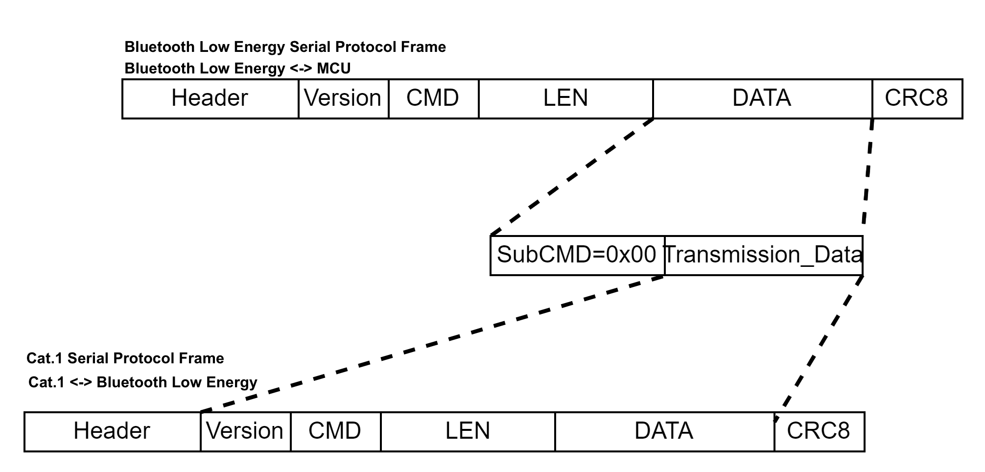
Cross-protocol data pass-through (0xC000)
The MCU can use this command to access the network module (such as the Cat.1 module) as instructed in LTE Cat.1 Serial Port Protocol to get information, such as positioning information.
Module <-> MCU:
| No. | Bytes | Field | Description |
|---|---|---|---|
| 0 1 |
2 | Header | 0x55 0xAA |
| 2 | 1 | Version number | 0x00 |
| 3 | 1 | Command (CMD) | 0xC0 |
| 4 5 |
2 | Data length (Len) | Upper 8 bits Lower 8 bits |
| 6 to 6+Len-1 | 1 | Subcommand | 0x00 |
| Len-1 | DATA | Includes the version number, command, data length, and data fields for the pass-through protocol. | |
| 6+Len | 1 | CRC8 | Start from the header, add up all the bytes, and then divide the sum by 256 to get the remainder. |
Control the power of extended module (0xC001)
- You need to consider the specific hardware design when using this command. The Bluetooth module only grants the MCU permissions to control the GPIO level.
- See the Bluetooth module datasheet or hardware design for details on the pin used for power control of the extended module.
- The configuration can be retained after power off. When the Bluetooth module is reset, the level of the Bluetooth module might flip. After the Bluetooth module is ready, the previous pin configuration will be restored.
If the extended module is not designed as automatic power-on, the MCU needs to pay special attention to scenarios where Bluetooth restarts may cause the cellular module to lose power. For example, when detecting that Bluetooth has restarted, it is necessary to add PWRKEY control logic. Each time CMD-0x01 is received, it can be regarded as a Bluetooth restart.
The MCU sends the following data.
| No. | Bytes | Field | Description |
|---|---|---|---|
| 0 1 |
2 | Header | 0x55 0xAA |
| 2 | 1 | Version number | 0x00 |
| 3 | 1 | Command (CMD) | 0xC0 |
| 4 5 |
2 | Data length (Len) | Upper 8 bits Lower 8 bits |
| 6 to 6+Len-1 | 1 | Subcommand | 0x01 |
| Len-1 | DATA | See the following table | |
| 6+Len | 1 | CRC8 | Start from the header, add up all the bytes, and then divide the sum by 256 to get the remainder. |
Data format:
| 1 byte | 1 byte |
|---|---|
op_type |
op_object |
-
op_type:0x01: Notify. When the MCU bypasses the Bluetooth module and directly controls the power on/off of the extended module, it notifies the Bluetooth module to update the power status.0x02: Control. The MCU controls the power on/off of the extended module through the specific pin on the Bluetooth module.0x03: Read. The MCU reads the power status of the extended module.
-
op_object:bit0: The pin to control the power of the extended module 1 (cellular module).0indicates read/write is low level, and1indicates read/write is high level.bit1: The pin to control the power of the extended module 2 (GPS module).0indicates read/write is low level, and1indicates read/write is high level.- All other bits are reserved.
The module returns the following data.
| No. | Bytes | Field | Description |
|---|---|---|---|
| 0 1 |
2 | Header | 0x55 0xAA |
| 2 | 1 | Version number | 0x00 |
| 3 | 1 | Command (CMD) | 0xC0 |
| 4 5 |
2 | Data length (Len) | Upper 8 bits Lower 8 bits |
| 6 to 6+Len-1 | 1 | Subcommand | 0x01 |
| Len-1 | DATA | See the following table | |
| 6+Len | 1 | CRC8 | Start from the header, add up all the bytes, and then divide the sum by 256 to get the remainder. |
Data format:
| 1 byte | 1 byte | 1 byte |
|---|---|---|
op_type |
op_object |
status |
status:
0x00: Success- Other values: Failure
Query the extended module’s presence (0xC002)
- When the cellular module is inserted or removed, the Bluetooth module notifies the MCU of this event. Alternatively, the MCU can proactively request the presence of the extended module.
- When the cellular module is removed, in order to reduce power consumption, before the MCU enters low power mode, you should send a power control command to power off the extended module.
The MCU sends the following data.
| No. | Bytes | Field | Description |
|---|---|---|---|
| 0 1 |
2 | Header | 0x55 0xAA |
| 2 | 1 | Version number | 0x00 |
| 3 | 1 | Command (CMD) | 0xC0 |
| 4 5 |
2 | Data length (Len) | Upper 8 bits Lower 8 bits |
| 6 | 1 | Subcommand | 0x02 |
| 7 | 1 | CRC8 | Start from the header, add up all the bytes, and then divide the sum by 256 to get the remainder. |
The module returns the following data.
| No. | Bytes | Field | Description |
|---|---|---|---|
| 0 1 |
2 | Header | 0x55 0xAA |
| 2 | 1 | Version number | 0x00 |
| 3 | 1 | Command (CMD) | 0xC0 |
| 4 5 |
2 | Data length (Len) | Upper 8 bits Lower 8 bits |
| 6 | 1 | Subcommand | 0x02 |
| 7 | 1 | Status |
|
| 8 | 1 | CRC8 | Start from the header, add up all the bytes, and then divide the sum by 256 to get the remainder. |
Configure extended module (0xC003)
- You can choose to configure the extended module through MCU, including the
apn,cops,m,mht,dp_cache,dp_ack, andbaudrateoptions. - The configuration is stored in the nonvolatile memory.
- The Bluetooth module will automatically configure the extended module according to this setting at the appropriate time.
- The Bluetooth module will retain the last configuration. When the configuration changes, the Bluetooth module will reset the cellular module to apply the new configuration. Therefore, dynamic configuration is prohibited, otherwise it might affect the cellular network status.
The MCU sends the following data.
| No. | Bytes | Field | Description |
|---|---|---|---|
| 0 1 |
2 | Header | 0x55 0xAA |
| 2 | 1 | Version number | 0x00 |
| 3 | 1 | Command (CMD) | 0xC0 |
| 4 5 |
2 | Data length (Len) | Upper 8 bits Lower 8 bits |
| 6 | 1 | Subcommand | 0x03 |
| N | Configurations | { "apn":"", "cops":"", "m":0, "mht":120, "dp_cache":0, "dp_ack":0, "baudrate":921600 } All configurations are optional. If not specified, the module will automatically use the default values. baudrate only supports configuration of 9600, 115200, 460800 or 921600, and other configurations will not take effect. For the meaning of the values, see Query product information (0x01) in LTE Cat.1 Serial Port Protocol. |
|
| 6 + N | 1 | CRC8 | Start from the header, add up all the bytes, and then divide the sum by 256 to get the remainder. |
Example:
-
Set
apntocniotlike this{"apn":"cniot"}.55 AA 00 C0 00 10 03 7B 22 61 70 6E 22 3A 22 63 6E 69 6F 74 22 7D EB -
Clear
apnsettings like this{"apn":""}.55 AA 00 C0 00 0B 03 7B 22 61 70 6E 22 3A 22 22 7D C6 -
Set multiple options like this
{"apn":"cniot","m":0,"mht":100,"cops":"12345","dp_cache":1,"dp_ack":1}.55 AA 00 C0 00 47 03 7B 22 61 70 6E 22 3A 22 63 6E 69 6F 74 22 2C 22 6D 22 3A 30 2C 22 6D 68 74 22 3A 31 30 30 2C 22 63 6F 70 73 22 3A 22 31 32 33 34 35 22 2C 22 64 70 5F 63 61 63 68 65 22 3A 31 2C 22 64 70 5F 61 63 6B 22 3A 31 7D CB
The module returns the following data.
| No. | Bytes | Field | Description |
|---|---|---|---|
| 0 1 |
2 | Header | 0x55 0xAA |
| 2 | 1 | Version number | 0x00 |
| 3 | 1 | Command (CMD) | 0xC0 |
| 4 5 |
2 | Data length (Len) | Upper 8 bits Lower 8 bits |
| 6 | 1 | Subcommand | 0x03 |
| 7 | 1 | Status |
|
| 8 | 1 | CRC8 | Start from the header, add up all the bytes, and then divide the sum by 256 to get the remainder. |
Example: 55 AA 00 C0 00 02 03 00 C4
Query configuration of extended module (0xC004)
The MCU sends the following data.
| No. | Bytes | Field | Description |
|---|---|---|---|
| 0 1 |
2 | Header | 0x55 0xAA |
| 2 | 1 | Version number | 0x00 |
| 3 | 1 | Command (CMD) | 0xC0 |
| 4 5 |
2 | Data length (Len) | Upper 8 bits Lower 8 bits |
| 6 | 1 | Subcommand | 0x04 |
| 6 + N | 1 | CRC8 | Start from the header, add up all the bytes, and then divide the sum by 256 to get the remainder. |
Example: 55 AA 00 C0 00 01 04 C4
The module returns the following data.
| No. | Bytes | Field | Description |
|---|---|---|---|
| 0 1 |
2 | Header | 0x55 0xAA |
| 2 | 1 | Version number | 0x00 |
| 3 | 1 | Command (CMD) | 0xC0 |
| 4 5 |
2 | Data length (Len) | Upper 8 bits Lower 8 bits |
| 6 | 1 | Subcommand | 0x04 |
| 7 | 1 | Configurations | { "apn":"", "cops":"", "m":0, "mht":120, "dp_cache":0, "dp_ack":0, "baudrate":921600 } Print all configurations. For options that are not configured, the module will display the default values. For the meaning of the values, see Query product information (0x01) in LTE Cat.1 Serial Port Protocol. |
| 8 | 1 | CRC8 | Start from the header, add up all the bytes, and then divide the sum by 256 to get the remainder. |
Example:
55 AA 00 04 00 3D 04 7B 22 61 70 6E 22 3A 22 22 2C 22 63 6F 70 73 22 3A 22 22 2C 22 6D 22 3A 30 2C 22 6D 68 74 22 3A 31 32 30 2C 22 64 70 5F 63 61 63 68 65 22 3A 30 2C 22 64 70 5F 61 63 6B 22 3A 30 7D EA ({"apn":"","cops":"","m":0,"mht":120,"dp_cache":0,"dp_ack":0})
FAQs
What should I pay attention to during the OTA update process of the MCU over the cellular network?
The LTE Cat.1 serial protocol differs from the Bluetooth serial protocol, so a valid CRC32 checksum of the file cannot be sent during the OTA update process of the MCU over the cellular network. Therefore, the MD5 hash value of the file should be used for integrity verification.
If you have any problems with TuyaOS development, you can post your questions in the Tuya Developer Forum.
Is this page helpful?
YesFeedbackIs this page helpful?
YesFeedback


