Serial Communication Protocol
The serial protocol is used for serial communication between Tuya’s LTE Cat.1 module and the third-party MCU.
Terms
- Module: refers to Tuya’s LTE Cat.1 module in this topic. For more information, see LTE Cat.1 Module.
- GNSS: stands for Global Navigation Satellite System.
Serial communication
- Baud rate: 115200, 9600, 460800, and 921600. The baud rate will be automatically detected for two minutes. If not specified, the default baud rate of 115200 will be used.
- Data bit: 8
- Parity check: none
- Stop bit: 1
- Data flow control: none
- MCU: microcontroller unit. Your MCU communicates with Tuya’s modules through the serial port.
Feature description
Model comparison
The following table provides a comparison of LTE Cat.1 modules.
Yrepresents support.Nrepresents not support.Orepresents external-based support.
| Feature | LZ201CN LZ501CN |
LZ211CN | LZ201EU | LZ211EU | TCS600U | TCS600E TCS800E |
NL668 AM | MA510 | MC665EU MG661LA MG661EU MC661CN |
L511A | L511C L511E |
|---|---|---|---|---|---|---|---|---|---|---|---|
| Basic services | Y | Y | Y | Y | Y | Y | Y | Y | Y | Y | Y |
| Data point (DP) service | Y | Y | Y | Y | Y | Y | Y | Y | Y | Y | Y |
| MCU update | Y | Y | Y | Y | Y | Y | Y | Y | Y | Y | Y |
| Cellular service | Y | Y | Y | Y | Y | Y | Y | Y | Y | Y | Y |
| Password service | Y | Y | Y | Y | Y | N | N | N | N | N | N |
| Weather service | Y | Y | Y | Y | Y | Y | Y | Y | Y | Y | Y |
| Bluetooth Low Energy (LE) and LTE Cat.1 combo | Y | Y | Y | Y | Y | Y | Y | Y | Y | Y | Y |
| Positioning service | O | Y | O | Y | O | O | Y | O | O | O | O |
| AGNSS service | Y | Y | Y | Y | Y | Y | Y | Y | Y | Y | Y |
| Wi-Fi Scan | Y | Y | Y | Y | Y | Y | Y | N | Y | Y | N |
| Phone call service | Y | Y | Y | Y | Y | N | N | N | N | N | N |
| SMS service | Y | Y | Y | Y | Y | N | Y | N | N | N | N |
| Battery service | Y | Y | Y | Y | Y | N | N | N | N | N | N |
| Audio service | Y | Y | Y | Y | Y | N | N | N | N | N | N |
| Bluetooth service | Y | Y | N | N | N | N | N | N | N | N | N |
| Function control | Y | Y | Y | Y | Y | Y | Y | Y | Y | Y | Y |
| Extended services | Y | Y | Y | Y | Y | Y | Y | Y | Y | Y | Y |
| GPIO services | Y | Y | Y | Y | Y | N | N | N | Y | Y | Y |
| ADC services | Y | Y | Y | Y | Y | N | N | N | Y | Y | Y |
Wake-up pin convention
When the module has data to send to the MCU, the wake-up pin on the module will be pulled down to low for 60 ms by default. The following table lists the wake-up pin for different module models.
| Module model | Wake-up pin | UART pin | Description |
|---|---|---|---|
|
|
UART1 |
|
| L610EU | Pin 37 | UART1 |
|
| MA510GL | Pin 61 | UART3 |
|
| NL668AM | Pin 62 | 129(TX) 130(RX) | - |
| TCS800E | Pin 20 | UART1(RX17,TX18) | UART2(RX62,TX67) supports interfacing with Tuya’s GNSS module. |
| TCS600E | Pin 20 | UART1(RX31,TX32) | UART2(RX62,TX67) supports interfacing with Tuya’s GNSS module. |
| MC665EU | Pin 61 | UART1(RX18,TX19) | UART2(RX39,TX40) supports interfacing with Tuya’s GNSS module. |
| MC665CN MG661EU MG661LA |
Pin 20 | MAIN_TXD(18),MAIN_RXD(17) | AUX_UART(RX28,TX29) supports interfacing with Tuya’s GNSS module. |
| L511A L511C L511E |
Pin 20 | MAIN_TXD (18), MAIN_RXD (17) |
|
Module GPIO and ADC
| Module model | ADC | Reference voltage (mV) | Tuya GPIO | Pinout (physical pin indicated in parentheses) |
|---|---|---|---|---|
| LZ501 | 0-1 | 1250/2444/3233/5000 | 0 to 3, 5 (wake up), 9 to 10, 17 to 21, 26, 29 to 31 | See LZ501-CN Datasheet. |
| LZ211EAU | 0-2 | 1250/2444/3233/5000 | 0 to 3, 5, 7 to 11, 12 (wake up), 13 to 15, 17 to 19 | See LZ211-EAU Datasheet. |
| TCS600U | 0-1 | 1250/2444/3233/5000 | 5 (wake up), 8 (net_led), 9 to 12, 14 to 15, 17 to 22 |
See TCS600U Datasheet. |
| TCS600E TCS800E |
0-1 | 3,400 mV | 24 (wake up), others | See TCS600E Datasheet and TCS800E Datasheet. |
| MG665EU | 0-1 | VBAT, range (0 to VBAT) | 2, 4, 6 (wake up), 8 to 11, 14 to 23, 29 | 2 (38), 4 (41), 8 (39), 9 (40), 10 (75), 11 (76), 14 (21), 15 (20), 16 (78), 17 (77), 18 (82), 19 (85), 20 (84), 21 (83), 22 (100), 23 (99), 29 (56) |
| MC661CN MG661LA AMG661EU |
0-1 | VBAT, range (0 to VBAT) | 0, 1 (wake up), 2, 6 to 8, 10, 16 to 18, 20 to 22, 29 to 35, 42 to 43 | 0 (25), 2 (16), 6 (28), 7 (29), 8 (84), 10 (85), 16 (68), 17 (69), 18 (101), 20 (31), 21 (32), 22 (33), 29 (5), 30 (6), 31 (75), 32 (83), 33 (86), 34 (76), 35 (74), 42 (67), 43 (66) |
| L511A | 0-1 | 0 to 1.2V | 16, 19 (wake up the module in low power mode), 20 (wake up the MCU), 21-23, 25, 26, 30-33, 49-58, 78 | / |
| L511C L511E |
0-1 | 0-1.2V | 16, 19 (wake up the module in low power mode and cannot be used as GPIO), 20 (wake up the MCU), 21-23, 25 | / |
Frame format
| Field | Byte(s) | Description |
|---|---|---|
| Header | 2 | It is fixed to 0x55aa. |
| Version | 1 | It is used for updates and extensions. |
| Command | 1 | The frame type. |
| Data length | 2 | Big-endian format. |
| Data | N | - |
| Checksum | 1 | Start from the header, add up all the bytes, and then divide the sum by 256 to get the remainder. |
-
All data greater than one byte is transmitted in big-endian format.
-
Typically, one command is sent by one party and received by the other party synchronously. That is, one party sends a command and waits for a response from the other party. If the sender does not receive a correct response packet within a specified time period, the transmission times out.
For more information, see the Protocol list.
-
If the module does not respond to the MCU command within two minutes, the MCU must restart it. After the MA510 module completes an OTA update, it will restart without notifying the MCU. If the MA510 module starts with
uart3_txhigh, it will fail to start and require the MCU to trigger a restart. -
Both command sending and status reporting use asynchronous transmission. Assume that the module sends a control command X and the MCU reports status Y. The data transmission is performed as shown below.
-
The module sends a control command:
-
The MCU reports status:
-
Response format for unsupported commands
The module returns the following data.
| Field | Byte(s) | Description |
|---|---|---|
| Header | 2 | 0x55aa |
| Version | 1 | 0x00 |
| Command | 1 | 0xFF |
| Data length | 2 | 2+N (version information) |
| Data | 2+N |
|
| Checksum | 1 | Start from the header, add up all the bytes, and then divide the sum by 256 to get the remainder. |
Example: 55 AA 00 FF 00 07 70 24 31 2E 30 2E 31 87
Basic services
Heartbeat check (0x00)
-
The module sends heartbeats to the MCU every 15 seconds. If the MCU does not respond within the 90-second timeout period, the module considers a communication exception occurred and will restart the software.
-
The MCU can determine whether the module works properly by the regular heartbeat check. If the MCU does not receive a heartbeat packet as expected, it can use the reset pin to reset the module.
The module sends the following data.
| Field | Byte(s) | Description |
|---|---|---|
| Header | 2 | 0x55aa |
| Version | 1 | 0x00 |
| Command | 1 | 0x00 |
| Data length | 2 | 0x0000 |
| Data | 0 | None |
| Checksum | 1 | Start from the header, add up all the bytes, and then divide the sum by 256 to get the remainder. |
For example, 0x55aa 00 00 0000 ff
The MCU returns the following data.
| Field | Byte(s) | Description |
|---|---|---|
| Header | 2 | 0x55aa |
| Version | 1 | 0x03 |
| Command | 1 | 0x00 |
| Data length | 2 | 0x0001 |
| Data | 1 |
|
| Checksum | 1 | Start from the header, add up all the bytes, and then divide the sum by 256 to get the remainder. |
Example:
- The MCU returns
0x55aa 03 00 0001 00 03after a restart. - The MCU returns
0x55aa 03 00 0001 01 04except for the first response after a restart.
Query product information (0x01)
Product information consists of the product ID (PID) and the MCU software version number.
- PID: a unique identifier assigned to each product created on the Developer Platform for storing product information in the cloud.
- MCU software version number: It is expressed in dot-decimal notation
x.x.xwherexis a decimal digit between 0 and 99.
The module sends the following data.
| Field | Byte(s) | Description |
|---|---|---|
| Header | 2 | 0x55aa |
| Version | 1 | 0x00 |
| Command | 1 | 0x01 |
| Data length | 2 | 0x0000 |
| Data | 0 | None |
| Checksum | 1 | Start from the header, add up all the bytes, and then divide the sum by 256 to get the remainder. |
Example: 0x55aa 00 01 0000 00
The MCU returns the following data.
| Field | Byte(s) | Description |
|---|---|---|
| Header | 2 | 0x55aa |
| Version | 1 | 0x03 |
| Command | 1 | 0x01 |
| Data length | 2 | N |
| Data | N | {"p":"AIp08kLIftb8x2x0", "v":"1.0.0", "m":1, "apn":"xxx", "mht":60, "qr":1, "slave":1, "ext_ota":[{ "ch":1, "v":"0.1.1" }, … { "ch":n, "v":"0.1.n" }], "U":0, "dp_cache":1, "cops":"xxx" "dp_ack":1, "online_tts":0 } apn is optional. If the apn is not configured, the system will automatically set it based on the SIM card. Typically, apn configuration is required for SIM cards from tier 2 carriers. mht, qr, and slave are optional. |
| Checksum | 1 | Start from the header, add up all the bytes, and then divide the sum by 256 to get the remainder. |
Example: {"p":"AIp08kLIftb8x2x0", "v":"1.0.0", "m":1}
-
p: indicates the PID isAIp08kLIftb8x2x0. -
v: indicates the MCU version is 1.0.0. -
m: indicates the power consumption of the module.0: standard power.1: low power. The period of the provided timer is one second.
-
mht: indicates the MQTT heartbeat interval for the module, in seconds. The default value is 300 seconds. -
qr: specifies whether to get the short URL of the QR code for pairing.1: Get the short URL.0: Not get the short URL. If a device has been paired, the short URL will not be pulled.
-
slave: specifies whether the LTE Cat.1 module works in tandem with a Bluetooth LE module. -
ext_ota: OTA update for subordinate MCU firmware.v: version information. The maximum length is 10 bytes, with up to six update channels supported. The update channels dedicated to the application firmware and basic firmware must not be used. -
U: specifies the protocol for MCU OTA updates.0: protocol version 01: protocol version 1- If
slaveis set andUis not set, protocol version 0 is used. - If both
slaveandUare set,0and1represent protocol version 0 and protocol version 1 respectively. - If both
slaveandUare not set, protocol version 0 is used. - If
slaveis not set andUis set,0and1represent protocol version 0 and protocol version 1 respectively.
- If
-
dp_cache: specifies whether to enable DP cache. DP cache requires an additional cloud-based feature. For more information, contact your account manager.1: Enable.- Other values: Disable.
-
(Optional)
cops: specifies the public land mobile network (PLMN) of the mobile operator. The value must be numeric encoding. For example,cops:"20416"is equivalent to AT commandAT+COPS=1,2, "xxxxx". -
(Optional)
dp_ack: specifies whether to enable acknowledgment (ACK) response. Set it to1to enable ACK. If the module does not receive an ACK message after it sends DP data to the MCU, it will transmit the packet again. A packet can be retransmitted up to three times, with an ACK wait time of 500 ms. -
online_tts: setting it to1indicates that online text-to-speech (TTS) is supported. This feature applies when the module supports the audio service. -
gps: GPS model, defaulting to Unicore UFirebird. Allystar’s GPS module also applies. When using the assisted GNSS (AGNSS) service, you need to specify the GPS model. The MCU integration protocol must be v1.1.3 or later. -
env_pre:1for the staging environment, and other values for the production environment. The MCU integration protocol must be v1.1.3 or later. -
net_type(for MA510 only): The MCU integration protocol must be v1.1.4 or later.0or empty: Auto1: GSM2: LTE4: CATM5: NB-IoT
When specifying this field, check the supported network types of the module.
Query working mode (0x02)
The working mode indicates how the network status is indicated and the way to trigger module reset. Theoretically, the module can work in the following two modes:
-
The MCU works with the module to process network events.
- The module sends its current work status to the MCU through serial communication. The MCU controls the LED to indicate status accordingly.
- When the MCU detects a request to reset the module, it directs the module to reset through serial communication.
-
The module processes network events itself.
- The
NET_MODEpin on the module drives the LED indicator to indicate the network status. - The GPIO input signal determines module reset. When the module detects a low level on the reset pin for more than three seconds, it will trigger a reset action. The following command specifies the GPIO pins of the LED indicator and the reset button. This feature is not available in low power mode.
- In the module self-processing mode, the LED indicator can only be defined by
NET_MODE. In this case, the module does not report network status. - For MA510 modules, it is recommended to reserve the USB port for testing purposes on the local network at the fulfillment location.
- Ensure correct APN configuration, as a wrong one can lead to internet connection failure.
- The
The module sends the following data.
| Field | Byte(s) | Description |
|---|---|---|
| Header | 2 | 0x55aa |
| Version | 1 | 0x00 |
| Command | 1 | 0x02 |
| Data length | 2 | 0x0000 |
| Data | 0 | None |
| Checksum | 1 | Start from the header, add up all the bytes, and then divide the sum by 256 to get the remainder. |
For example, 0x55aa 00 02 0000 01
The MCU returns the following data.
| Field | Byte(s) | Description |
|---|---|---|
| Header | 2 | 0x55aa |
| Version | 1 | 0x03 |
| Command | 1 | 0x02 |
| Data length | 2 | 0x0000/0x0002
|
| Data | 0/2 | The data length is 2 bytes. The first byte indicates the GPIO pin of the LED indicator. The fixed value is 0. The second byte indicates the GPIO pin of the reset button. |
| Checksum | 1 | Start from the header, add up all the bytes, and then divide the sum by 256 to get the remainder. |
Example:
- The module works with the MCU to process network events:
0x55aa 03 02 0000 04is returned. - The module processes network events itself:
0x55aa 03 02 0002 0c0d 1fis returned.0x0cindicates the LED indicator is connected to GPIO12.0x0dindicates the reset button is connected to GPIO13.
Report network status (0x03)
| Network status | Description | Status value |
|---|---|---|
| Status 1 | The SIM card is not connected. | 0x00 |
| Status 2 | The module searches for cellular networks. | 0x01 |
| Status 3 | The module is registered with the cellular network but not connected to the network. | 0x02 |
| Status 4 | The module is connected to the network and gets an IP address. | 0x03 |
| Status 5 | The module has been connected to the cloud. | 0x04 |
| Status 6 | SIM card registration is denied, which might be because it is not subscribed to a cellular service provider. | 0x05 |
| Status 7 | The module is ready for pairing. | 0x06 |
| Status 8 | Unknown status | 0xFF |
- When the module detects that the MCU is restarted or reconnected, it will proactively send the current network status to the MCU.
- When the network status of the module changes, the module will proactively send its current status to the MCU.
- If you choose the module self-processing mode, implementing this protocol for your MCU is not necessary.
The module sends the following data.
| Field | Byte(s) | Description |
|---|---|---|
| Header | 2 | 0x55aa |
| Version | 1 | 0x00 |
| Command | 1 | 0x03 |
| Data length | 2 | 0x0001 |
| Data | 1 | See network status. |
| Checksum | 1 | Start from the header, add up all the bytes, and then divide the sum by 256 to get the remainder. |
For example, 0x55aa 00 03 0001 00 03
The MCU returns the following data.
| Field | Byte(s) | Description |
|---|---|---|
| Header | 2 | 0x55aa |
| Version | 1 | 0x03 |
| Command | 1 | 0x03 |
| Data length | 2 | 0x0000 |
| Data | 0 | None |
| Checksum | 1 | Start from the header, add up all the bytes, and then divide the sum by 256 to get the remainder. |
For example, 0x55aa 03 03 0000 05
Reset module (0x04)
When the LTE Cat.1 module receives the reset command, it unbinds the device from the cloud.
The MCU sends the following data.
| Field | Byte(s) | Description |
|---|---|---|
| Header | 2 | 0x55aa |
| Version | 1 | 0x03 |
| Command | 1 | 0x04 |
| Data length | 2 | 0x0000 |
| Data | 0 | None |
| Checksum | 1 | Start from the header, add up all the bytes, and then divide the sum by 256 to get the remainder. |
For example, 0x55aa 03 04 0000 06
The module returns the following data.
| Field | Byte(s) | Description |
|---|---|---|
| Header | 2 | 0x55aa |
| Version | 1 | 0x00 |
| Command | 1 | 0x04 |
| Data length | 2 | 0x0000 |
| Data | 0 | None |
| Checksum | 1 | Start from the header, add up all the bytes, and then divide the sum by 256 to get the remainder. |
Example: 0x55aa 00 04 0000 03
Get version information (0x71 41)
The MCU sends the following data.
| Field | Byte(s) | Description |
|---|---|---|
| Header | 2 | 0x55aa |
| Version | 1 | 0x03 |
| Command | 1 | 0x71 |
| Data length | 2 | 0x0001 |
| Data | 1 | Subcommand: 0x41 |
| Checksum | 1 | Start from the header, add up all the bytes, and then divide the sum by 256 to get the remainder. |
The module returns the following data.
| Field | Byte(s) | Description |
|---|---|---|
| Header | 2 | 0x55aa |
| Version | 1 | 0x00 |
| Command | 1 | 0x71 |
| Data length | 2 | 0x0002+n |
| Data | N |
|
| Checksum | 1 | Start from the header, add up all the bytes, and then divide the sum by 256 to get the remainder. |
DP services
Data units
The following table defines data units.
| Field | Byte(s) | Description |
|---|---|---|
| dpid | 1 | The ID of a DP. |
| type | 1 | The data type of a DP defined on the Developer Platform. For more information, see the description of the type field in the following table. |
| len | 2 | The length of a value, in bytes. For more information, see the description of the type field in the following table. |
| value | 1/2/4/N | Represented in hexadecimal format. Data greater than one byte is transmitted in big-endian format. |
Description of the type field
| Type | Data type | Byte(s) | Description |
|---|---|---|---|
| 0x00 | Raw | N | Represents a DP of raw data type. The module transmits the raw data to the receiver. |
| 0x01 | Boolean | 1 | Represents a DP of Boolean data type. Valid values:
|
| 0x02 | Value | 4 | Represents a DP of integer data type. The data is represented in big-endian format. |
| 0x03 | String | N | Represents a DP of string data type. |
| 0x04 | Enum | 1 | Represents a DP of enum data type, ranging from 0 to 255. |
| 0x05 | Bitmap | 1/2/4 | Data greater than one byte is transmitted in big-endian format. |
- Except for the
Rawdata type, all others belong to the object type. - One command can contain data units of multiple
DPs. - Asynchronous communication applies when the module sends control commands and the MCU reports DP status.
Send commands (0x06)
The module sends the following data.
| Field | Byte(s) | Description |
|---|---|---|
| Header | 2 | 0x55aa |
| Version | 1 | 0x00 |
| Command | 1 | 0x06 |
| Data length | 2 | It depends on the types and the number of data units. |
| Data | N | Data units |
| Checksum | 1 | Start from the header, add up all the bytes, and then divide the sum by 256 to get the remainder. |
Suppose that DP 3 of Boolean type is used for on/off control, and 1 means to turn on the device, the module sends 0x55aa 00 06 0005 03 01 0001 01 10 to the MCU.
Report status (0x07)
-
For more information, see Data units.
-
This is an asynchronous command. The MCU uses it to report device status to the module, which can be triggered by three mechanisms.
-
After the MCU executes the command received from the module, it reports the changed DP status to the module.
-
When the MCU proactively detects status changes of DPs, it reports the changed DP status to the module.
-
When the MCU receives the DP status query, it sends the status of all DPs to the module.
-
-
A piece of status data can contain data units of multiple DPs.
The MCU sends the following data.
| Field | Byte(s) | Description |
|---|---|---|
| Header | 2 | 0x55aa |
| Version | 1 | 0x03 |
| Command | 1 | 0x07 |
| Data length | 2 | It depends on the types and the number of data units. |
| Data | N | Data units |
| Checksum | 1 | Start from the header, add up all the bytes, and then divide the sum by 256 to get the remainder. |
Suppose that DP 5 of value type is used for reporting the current humidity, and the current humidity is 30%, the MCU reports 0x55aa 03 07 0008 05 02 0004 0000001e 3a to the module.
Query status (0x08)
-
The module asynchronously queries the status of all object DPs. When the MCU receives a query, it sends the status of DPs to the module through the command
0x07. -
The module sends a status query to the MCU when the following two events occur.
-
When powered on for the first time, the module sends a status query after it connects to the MCU and the Developer Platform.
-
When the module detects the MCU is restarted or disconnected and then goes online, the module sends a status query.
-
The module sends the following data.
| Field | Byte(s) | Description |
|---|---|---|
| Header | 2 | 0x55aa |
| Version | 1 | 0x00 |
| Command | 1 | 0x08 |
| Data length | 2 | 0x0000 |
| Data | 0 | None |
| Checksum | 1 | Start from the header, add up all the bytes, and then divide the sum by 256 to get the remainder. |
Example: 0x55aa 00 08 0000 07
Report non-record type status (0x22)
-
This is a synchronous command. The MCU reports DP status and then waits for the result from the module.
-
The MCU should not send a new request until receiving a response to the previous status reporting.
-
If the data fails to be reported to the cloud due to poor network quality, the module will return a failure code five seconds later. In this case, the MCU should wait for more than five seconds.
-
For more information, see Data units.
-
A piece of status data can contain data units of multiple DPs.
The MCU sends the following data.
| Field | Byte(s) | Description |
|---|---|---|
| Header | 2 | 0x55aa |
| Version | 1 | 0x03 |
| Command | 1 | 0x22 |
| Data length | 2 | It depends on the types and the number of data units. |
| Data | N | Data units |
| Checksum | 1 | Start from the header, add up all the bytes, and then divide the sum by 256 to get the remainder. |
The module returns the following data.
| Field | Byte(s) | Description |
|---|---|---|
| Header | 2 | 0x55aa |
| Version | 1 | 0x00 |
| Command | 1 | 0x23 |
| Data length | 2 | 0x01 |
| Data | 1 | 0x00: Failure. 0x01: Success. |
| Checksum | 1 | Start from the header, add up all the bytes, and then divide the sum by 256 to get the remainder. |
Report record type status (0x26)
-
This is a synchronous command. The MCU reports DP status and then waits for the result from the module.
-
The MCU should not send a new request until receiving a response to the previous status reporting.
-
If the data fails to be reported to the cloud due to poor network quality, the module will return a failure code five seconds later. In this case, the MCU should wait for more than five seconds.
-
For more information, see Data units.
-
A piece of status data can contain data units of multiple DPs.
The MCU sends the following data.
| Field | Byte(s) | Description |
|---|---|---|
| Header | 2 | 0x55aa |
| Version | 1 | 0x03 |
| Command | 1 | 0x26 |
| Data length | 2 | The length of the DP data unit plus seven |
| Timestamp | 7 |
|
| Data | N | Data units |
| Checksum | 1 | Start from the header, add up all the bytes, and then divide the sum by 256 to get the remainder. |
The module returns the following data.
| Field | Byte(s) | Description |
|---|---|---|
| Header | 2 | 0x55aa |
| Version | 1 | 0x00 |
| Command | 1 | 0x26 |
| Data length | 2 | 0x0001 |
| Data | 1 |
|
| Checksum | 1 | Start from the header, add up all the bytes, and then divide the sum by 256 to get the remainder. |
MCU firmware update
-
You can specify the method for the OTA firmware update. The module only serves as the channel for update transmission, without any data parsing operation.
-
Developer Platform provides four update methods.
-
Update notification: Users receive a firmware update notification on the app and choose whether to install updates.
-
Automatic update: Users will not receive any update pop-up window. The module checks for firmware updates within one minute after power-on. If any new version is available, it will automatically pull the updates. The module checks for updates every 24 hours after the first-time power-on.
-
Forced update: Users receive a firmware update notification on the app and have no option but to update the firmware.
-
Check for updates: Users will not receive a firmware update notification on the app but need to manually check for new updates.
-
-
After the update packet transmission is finished, the module will send the command
0x01to the MCU to query the product information. The MCU must reply with the new MCU firmware version number within one minute. The new version number should be consistent with that configured on the Developer Platform. The following flowchart shows how the OTA firmware update works.```mermaid graph TD a("Initiate update") b("Send packet") c("Is packet sent three times?") d("Receive a reply from MCU within 5s?") e("The last packet?") f("Send the next packet?") g("Update failed") h("Module sends product information query.
MCU should reply success and its latest version number") i("Update succeeded") --> --> c -- --> --> --> f c -- --> g e -- --> h -- --> g h -- --> i d -- --> b ```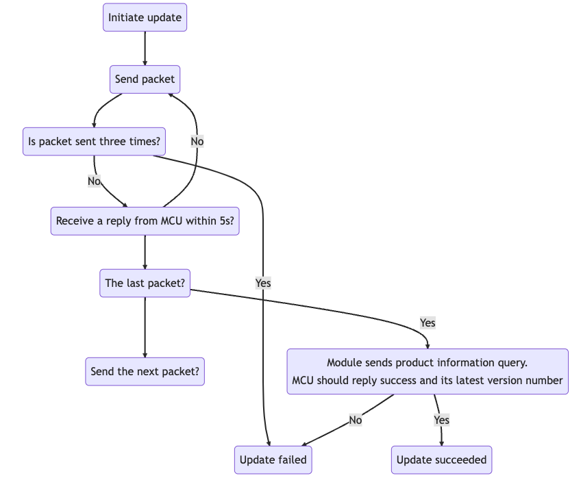
Initiate update (0x0a)
The OTA update can be initiated automatically or manually.
- For automatic updates, when the module detects MCU firmware updates from the cloud, the transmission of the update file automatically starts.
- For manual updates, the module initiates updates only when updates are confirmed on the app.
The module sends the following data.
-
U: protocol version 0 (0x00)Field Byte(s) Description Header 2 0x55aa Version 1 0x00 Command 1 0x0a Data length 2 0x0004 Data 4 The size of the update file in bytes. The data type is an unsigned integer, and the data is transmitted in big-endian format. Checksum 1 Start from the header, add up all the bytes, and then divide the sum by 256 to get the remainder. For example,
0x55aa 00 0a 0004 00006800 75indicates the size of the update file is 26624 bytes (26 KB). -
U: protocol version 1 (0x01)Field Byte(s) Description Header 2 0x55aa Version 1 0x01 Command 1 0x0a Data length 2 0x004F Data 40 - 4-byte update file. The data type is an unsigned integer, and the data is transmitted in big-endian format.
- 32-byte MD5 hash.
- 1-byte update channel.
- 3-byte version number. For example, version
01.2.04is010204.
Checksum 1 Start from the header, add up all the bytes, and then divide the sum by 256 to get the remainder.
The MCU returns the following data.
| Field | Byte(s) | Description |
|---|---|---|
| Header | 2 | 0x55aa |
| Version | 1 | 0x03 |
| Command | 1 | 0x0a |
| Data length | 2 | 0x0001 |
| Data | 1 | The options for the maximum size of each packet:
|
| Checksum | 1 | Start from the header, add up all the bytes, and then divide the sum by 256 to get the remainder. |
For example, 0x55aa 03 0a 0001 00 0d
Transmit update file (0x0b)
-
Data format: the channel ID (for protocol version
01) + packet offset (unsigned short) + payload. -
When the MCU receives a frame with a data length equal to 4 bytes and the packet offset is equal to or greater than the size of the update, the transfer is completed.
-
For the last packet, the packet offset is the firmware size, and the packet length is 0 bytes.
The module sends the following data.
-
U: protocol version 0 (0x00)Field Byte(s) Description Header 2 0x55aa Version 1 0x00 Command 1 0x0b Data length 2 The data length is the sum of 0x0004and the packet length.Data 4+N The first four bytes are fixed as packet offset, and the latter bytes are the actual data. Checksum 1 Start from the header, add up all the bytes, and then divide the sum by 256 to get the remainder. -
U: protocol version 1 (0x01)Field Byte(s) Description Header 2 0x55aa Version 1 0x01 Command 1 0x0b Data length 2 The data length is the sum of 0x0005and the packet length.Data 5+N - 1-byte update channel.
- The first four bytes are fixed as packet offset.
- The latter bytes are the actual data.
Checksum 1 Start from the header, add up all the bytes, and then divide the sum by 256 to get the remainder.
Assume that the size of the update is 530 bytes, and the MCU does not need to respond to the last packet.
- For the first packet, the packet offset is
0x00000000, and the packet length is 256 bytes. The module sends0x55aa 00 0b 0104 00000000 xx … xx XX. - For the second packet, the packet offset is
0x00000100, and the packet length is 256 bytes. The module sends0x55aa 00 0b 0104 00000100 xx … xx XX. - For the third packet, the packet offset is
0x00000200, and the packet length is 18 bytes. The module sends0x55aa 00 0b 0016 00000200 xx … xx XX. - For the last packet, the packet offset is
0x00000212, and the packet length is 0 bytes. The module sends0x55aa 00 0b 0004 00000212 xx … xx XX.
The MCU returns the following data.
| Field | Byte(s) | Description |
|---|---|---|
| Header | 2 | 0x55aa |
| Version | 1 | 0x03 |
| Command | 1 | 0x0b |
| Data length | 2 | 0x0000 |
| Data | 0 | None |
| Checksum | 1 | Start from the header, add up all the bytes, and then divide the sum by 256 to get the remainder. |
For example, 0x55aa 03 0b 0000 0d
Notify MCU of result (0x34 09)
The module sends the following data.
| Field | Byte(s) | Description |
|---|---|---|
| Header | 2 | 0x55aa |
| Version | 1 | 0x00 |
| Command | 1 | 0x34 |
| Data length | 2 | 0x0002 |
| Data | 2 |
|
| Checksum | 1 | Start from the header, add up all the bytes, and then divide the sum by 256 to get the remainder. |
The MCU returns the following data.
| Field | Byte(s) | Description |
|---|---|---|
| Header | 2 | 0x55aa |
| Version | 1 | 0x03 |
| Command | 1 | 0x34 |
| Data length | 2 | 0x0001 |
| Data | 1 | Subcommand: 0x09 |
| Checksum | 1 | Start from the header, add up all the bytes, and then divide the sum by 256 to get the remainder. |
Cellular services
Get system time in GMT (0x0c)
- As the international standard of civil time, GMT is independent of the time zone and DST.
- After connecting to the network, the module returns success and valid time data after the local timestamp is synced.
The MCU sends the following data.
| Field | Byte(s) | Description |
|---|---|---|
| Header | 2 | 0x55aa |
| Version | 1 | 0x03 |
| Command | 1 | 0x0c |
| Data length | 2 | 0x0000 |
| Data | 0 | None |
| Checksum | 1 | Start from the header, add up all the bytes, and then divide the sum by 256 to get the remainder. |
For example, 0x55aa 03 0c 0000 0e
The module returns the following data.
| Field | Byte(s) | Description |
|---|---|---|
| Header | 2 | 0x55aa |
| Version | 1 | 0x00 |
| Command | 1 | 0x0c |
| Data length | 2 | 0x0007 |
| Data | 7 |
|
| Checksum | 1 | Start from the header, add up all the bytes, and then divide the sum by 256 to get the remainder. |
For example, 0x55aa 00 0c 0007 01 10 04 13 05 06 07 4c indicates the time 05:06:07 on April 19, 2016 in GMT.
Test module functionality (0x0e)
- Insert the SIM card into the module to test whether the card can be detected.
- Test whether the module is authorized.
- Test whether the RF is calibrated.
- Get the 4G signal strength. A SIM card must be inserted. Signal strength ranges from 0 to 31. You can set a quality standard as needed.
The MCU sends the following data.
| Field | Byte(s) | Description |
|---|---|---|
| Header | 2 | 0x55aa |
| Version | 1 | 0x03 |
| Command | 1 | 0x0e |
| Data length | 2 | 0x0000 |
| Data | 0 | None |
| Checksum | 1 | Start from the header, add up all the bytes, and then divide the sum by 256 to get the remainder. |
The module returns the following data.
| Field | Byte(s) | Description |
|---|---|---|
| Header | 2 | 0x55aa |
| Version | 1 | 0x00 |
| Command | 1 | 0x0e |
| Data length | 2 | 0x0004 |
| Data | 4 |
|
| Checksum | 1 | Start from the header, add up all the bytes, and then divide the sum by 256 to get the remainder. |
Get local time (0x1c)
- The local time is calculated by adding the time zone offset and DST to the GMT. The time zone is where the device is activated.
- After connecting to the network, the module returns success and valid time data after the local timestamp is synced.
The MCU sends the following data.
| Field | Byte(s) | Description |
|---|---|---|
| Header | 2 | 0x55aa |
| Version | 1 | 0x03 |
| Command | 1 | 0x1c |
| Data length | 2 | 0x0000 |
| Data | 0 | None |
| Checksum | 1 | Start from the header, add up all the bytes, and then divide the sum by 256 to get the remainder. |
The module returns the following data.
| Field | Byte(s) | Description |
|---|---|---|
| Header | 2 | 0x55aa |
| Version | 1 | 0x00 |
| Command | 1 | 0x1c |
| Data length | 2 | 0x0008 |
| Data | 8 |
|
| Checksum | 1 | Start from the header, add up all the bytes, and then divide the sum by 256 to get the remainder. |
Example:
- If the device is activated in mainland China, the local time is Beijing time (GMT+08:00). For example, the module returns
0x55aa 00 1c 0008 01 10 04 13 05 06 07 02 5fto indicate Beijing time at 05:06:07 on April 19, 2016. - If the device is activated in other countries or regions, the local time is the time zone in which the device is located.
Get module’s memory (0x0f)
This command can be used to get the module’s remaining memory. If the module returns -1, getting the module’s remaining memory is not supported.
The MCU sends the following data.
| Field | Byte(s) | Description |
|---|---|---|
| Header | 2 | 0x55aa |
| Version | 1 | 0x03 |
| Command | 1 | 0x0f |
| Data length | 2 | 0x0000 |
| Data | 0 | None |
| Checksum | 1 | Start from the header, add up all the bytes, and then divide the sum by 256 to get the remainder. |
The module returns the following data.
| Field | Byte(s) | Description |
|---|---|---|
| Header | 2 | 0x55aa |
| Version | 1 | 0x00 |
| Command | 1 | 0x0f |
| Data length | 2 | 0x0004 |
| Data | 4 | The value is represented in big-endian format. For example, 0x00 0x00 0x28 0x00 represents 10240 bytes remaining memory. |
| Checksum | 1 | Start from the header, add up all the bytes, and then divide the sum by 256 to get the remainder. |
Get Unix timestamp (with time zone) (0x1b)
- The MCU can get a Unix timestamp, time zone, and daylight saving time (DST).
- This command only applies to door locks with the keep-alive feature.
The MCU sends the following data.
| Field | Byte(s) | Description |
|---|---|---|
| Header | 2 | 0x55aa |
| Version | 1 | 0x03 |
| Command | 1 | 0x1B |
| Data length | 2 | 0x0000 |
| Data | 0 | None |
| Checksum | 1 | Start from the header, add up all the bytes, and then divide the sum by 256 to get the remainder. |
The module returns the following data.
| Field | Byte(s) | Description |
|---|---|---|
| Header | 2 | 0x55aa |
| Version | 1 | 0x00 |
| Command | 1 | 0x1B |
| Data length | 2 | N |
| Data | N |
|
| Checksum | 1 | Start from the header, add up all the bytes, and then divide the sum by 256 to get the remainder. |
Currently, getting the DST is not supported.
(Optional) Get signal strength (0x24)
The MCU sends the following data.
| Field | Byte(s) | Description |
|---|---|---|
| Header | 2 | 0x55aa |
| Version | 1 | 0x03 |
| Command | 1 | 0x24 |
| Data length | 2 | 0x0000 |
| Data | 0 | None |
| Checksum | 1 | Start from the header, add up all the bytes, and then divide the sum by 256 to get the remainder. |
The module returns the following data.
| Field | Byte(s) | Description |
|---|---|---|
| Header | 2 | 0x55aa |
| Version | 1 | 0x00 |
| Command | 1 | 0x24 |
| Data length | 2 | 0x0001 |
| Data | 1 | The RSSI value ranges from 0 to 31. The larger the value, the better the signal quality.
|
| Checksum | 1 | Start from the header, add up all the bytes, and then divide the sum by 256 to get the remainder. |
(Optional) Notify module to disable heartbeat (0x25)
The MCU sends the following data.
-
Version 03:
Field Byte(s) Description Header 2 0x55aa Version 1 0x03 Command 1 0x25 Data length 2 0x0000 Data 0 None Checksum 1 Start from the header, add up all the bytes, and then divide the sum by 256 to get the remainder. -
Version 04:
Field Byte(s) Description Header 2 0x55aa Version 1 0x04 Command 1 0x25 Data length 2 0x0001 Data 1 0: Disable.1: Enable.
Checksum 1 Start from the header, add up all the bytes, and then divide the sum by 256 to get the remainder.
The module returns the following data.
| Field | Byte(s) | Description |
|---|---|---|
| Header | 2 | 0x55aa |
| Version | 1 | 0x00 |
| Command | 1 | 0x25 |
| Data length | 2 | 0x0000 or 0x0001 |
| Data | 0 or 1 |
|
| Checksum | 1 | Start from the header, add up all the bytes, and then divide the sum by 256 to get the remainder. |
Before the module goes to sleep for reducing power consumption, the MCU can send this command to notify the module to disable the heartbeat. Because heartbeats are required for building communication between the module and the MCU, this command must not be sent when the device is just powered on.
Get network status (0x2b)
| Network status | Description | Status value |
|---|---|---|
| Status 1 | The SIM card is not connected. | 0x00 |
| Status 2 | The module searches for cellular networks. | 0x01 |
| Status 3 | The module is registered with the cellular network but not connected to the network. | 0x02 |
| Status 4 | The module is connected to the network and gets an IP address. | 0x03 |
| Status 5 | The module is connected to the cloud. | 0x04 |
| Status 6 | SIM card registration is denied. | 0x05 |
The status definition must be consistent with that in Report network status.
The MCU sends the following data.
| Field | Byte(s) | Description |
|---|---|---|
| Header | 2 | 0x55aa |
| Version | 1 | 0x03 |
| Command | 1 | 0x2b |
| Data length | 2 | 0x0000 |
| Data | 0 | None |
| Checksum | 1 | Start from the header, add up all the bytes, and then divide the sum by 256 to get the remainder. |
The module returns the following data.
| Field | Byte(s) | Description |
|---|---|---|
| Header | 2 | 0x55aa |
| Version | 1 | 0x00 |
| Command | 1 | 0x2b |
| Data length | 2 | 0x0001 |
| Data | 1 | See network status. |
| Checksum | 1 | Start from the header, add up all the bytes, and then divide the sum by 256 to get the remainder. |
Get module’s MAC address (0x2d)
The MCU sends the following data.
| Field | Byte(s) | Description |
|---|---|---|
| Header | 2 | 0x55aa |
| Version | 1 | 0x03 |
| Command | 1 | 0x2d |
| Data length | 2 | 0x0000 |
| Data | 0 | None |
| Checksum | 1 | Start from the header, add up all the bytes, and then divide the sum by 256 to get the remainder. |
The module returns the following data.
| Field | Byte(s) | Description |
|---|---|---|
| Header | 2 | 0x55aa |
| Version | 1 | 0x00 |
| Command | 1 | 0x2d |
| Data length | 2 | 0x0007 |
| Data | 7 |
|
Set cellular mode (0x05)
The module can work in fully operational mode or airplane mode.
The MCU sends the following data.
| Field | Byte(s) | Description |
|---|---|---|
| Header | 2 | 0x55aa |
| Version | 1 | 0x03 |
| Command | 1 | 0x05 |
| Data length | 2 | 0x0001 |
| Data | 1 |
|
| Checksum | 1 | Start from the header, add up all the bytes, and then divide the sum by 256 to get the remainder. |
For example, 0x55aa 03 04 0000 06
The module returns the following data.
| Field | Byte(s) | Description |
|---|---|---|
| Header | 2 | 0x55aa |
| Version | 1 | 0x00 |
| Command | 1 | 0x05 |
| Data length | 2 | 0x0001 |
| Data | 1 |
|
| Checksum | 1 | Start from the header, add up all the bytes, and then divide the sum by 256 to get the remainder. |
Example: 0x55aa 00 04 0000 03
Get cellular mode (0x71 01)
The module can work in fully operational mode or airplane mode.
The MCU sends the following data.
| Field | Byte(s) | Description |
|---|---|---|
| Header | 2 | 0x55aa |
| Version | 1 | 0x03 |
| Command | 1 | 0x71 |
| Data length | 2 | 0x0001 |
| Data | 1 | Subcommand: 0x01 |
| Checksum | 1 | Start from the header, add up all the bytes, and then divide the sum by 256 to get the remainder. |
For example, 55 AA 03 71 00 01 01 75
The module returns the following data.
| Field | Byte(s) | Description |
|---|---|---|
| Header | 2 | 0x55aa |
| Version | 1 | 0x00 |
| Command | 1 | 0x71 |
| Data length | 2 | 0x0002 |
| Data | 2 |
|
| Checksum | 1 | Start from the header, add up all the bytes, and then divide the sum by 256 to get the remainder. |
Get IMSI (0x71 02)
The MCU can send this command to the module to get the international mobile subscriber identity (IMSI) of the module.
The MCU sends the following data.
| Field | Byte(s) | Description |
|---|---|---|
| Header | 2 | 0x55aa |
| Version | 1 | 0x03 |
| Command | 1 | 0x71 |
| Data length | 2 | 0x0001 |
| Data | 1 | Subcommand: 0x02 |
| Checksum | 1 | Start from the header, add up all the bytes, and then divide the sum by 256 to get the remainder. |
The module returns the following data.
| Field | Byte(s) | Description |
|---|---|---|
| Header | 2 | 0x55aa |
| Version | 1 | 0x00 |
| Command | 1 | 0x71 |
| Data length | 2 | 0x0010 |
| Data | 16 |
|
| Checksum | 1 | Start from the header, add up all the bytes, and then divide the sum by 256 to get the remainder. |
Example:
55 AA 00 71 00 10 02 34 36 30 31 31 33 30 31 32 34 36 37 33 34 30 7C
Get ICCID number (0x71 03)
The MCU can send this command to the module to get the integrated circuit card identifier (ICCID). The module returns a 20-digit ICCID number to the MCU.
The MCU sends the following data.
| Field | Byte(s) | Description |
|---|---|---|
| Header | 2 | 0x55aa |
| Version | 1 | 0x03 |
| Command | 1 | 0x71 |
| Data length | 2 | 0x0001 |
| Data | 1 | Subcommand: 0x03 |
| Checksum | 1 | Start from the header, add up all the bytes, and then divide the sum by 256 to get the remainder. |
The module returns the following data.
| Field | Byte(s) | Description |
|---|---|---|
| Header | 2 | 0x55aa |
| Version | 1 | 0x00 |
| Command | 1 | 0x71 |
| Data length | 2 | 0x0015 |
| Data | 21 |
|
| Checksum | 1 | Start from the header, add up all the bytes, and then divide the sum by 256 to get the remainder. |
Example:
55 AA 00 71 00 15 03 38 39 38 36 31 31 31 38 32 34 39 30 30 30 33 36 33 34 39 30 9A
Get IMEI (0x71 04)
The MCU can send this command to request the 15-digit international mobile equipment identity (IMEI) of the module.
The MCU sends the following data.
| Field | Byte(s) | Description |
|---|---|---|
| Header | 2 | 0x55aa |
| Version | 1 | 0x03 |
| Command | 1 | 0x71 |
| Data length | 2 | 0x0001 |
| Data | 1 | Subcommand: 0x04 |
| Checksum | 1 | Start from the header, add up all the bytes, and then divide the sum by 256 to get the remainder. |
The module returns the following data.
| Field | Byte(s) | Description |
|---|---|---|
| Header | 2 | 0x55aa |
| Version | 1 | 0x00 |
| Command | 1 | 0x71 |
| Data length | 2 | 0x0010 |
| Data | 16 |
|
| Checksum | 1 | Start from the header, add up all the bytes, and then divide the sum by 256 to get the remainder. |
Example:
55 AA 00 71 00 10 04 38 36 34 32 33 37 30 34 30 30 31 34 37 33 33 88
Get cellular network type (0x71 43)
The MCU sends the following data.
| Field | Byte(s) | Description |
|---|---|---|
| Header | 2 | 0x55aa |
| Version | 1 | 0x03 |
| Command | 1 | 0x71 |
| Data length | 2 | 0x0001 |
| Data | 1 | Subcommand: 0x43 |
| Checksum | 1 | Start from the header, add up all the bytes, and then divide the sum by 256 to get the remainder. |
The module returns the following data.
| Field | Byte(s) | Description |
|---|---|---|
| Header | 2 | 0x55aa |
| Version | 1 | 0x00 |
| Command | 1 | 0x71 |
| Data length | 2 | 0x0002 |
| Data | 2 |
|
| Checksum | 1 | Start from the header, add up all the bytes, and then divide the sum by 256 to get the remainder. |
Query the current PLMN (0x71 48)
-
This command applies to the MA510 module only and is available when
COPSis specified by the MCU in the product information. -
The module can return the PLMN only after it successfully registers to the network.
The MCU sends the following data.
| Field | Bytes | Description |
|---|---|---|
| Header | 2 | 0x55aa |
| Version | 1 | 0x03 |
| Command | 1 | 0x71 |
| Data length | 2 | 0x0001 |
| Data | 3 | Data[0] Subcommand: 0x48 |
| Checksum | 1 | Start from the header, add up all the bytes, and then divide the sum by 256 to get the remainder. |
The module returns the following data.
| Field | Bytes | Description |
|---|---|---|
| Header | 2 | 0x55aa |
| Version | 1 | 0x00 |
| Command | 1 | 0x71 |
| Data length | 2 | 0x0002 + N × PLMN |
| Data | 3 |
|
| Checksum | 1 | Start from the header, add up all the bytes, and then divide the sum by 256 to get the remainder. |
Example:
-
55 AA 03 71 00 01 48 BC
-
55 AA 00 71 00 12 48 01 00 04 BA FC 00 04 BA FC 00 04 BC 8A 00 04 BB F4 3C
(Optional) Set or get radio resource control (RRC) (0x71 4A)
The MCU integration protocol must be v1.1.1 or later.
The MCU sends the following data.
| Field | Bytes | Description |
|---|---|---|
| Header | 2 | 0x55aa |
| Version | 1 | 0x03 |
| Command | 1 | 0x71 |
| Data length | 2 | 0x0002/0x0003 |
| Data | 0x0002/0x0003 |
|
| Checksum | 1 | Start from the header, add up all the bytes, and then divide the sum by 256 to get the remainder. |
The module returns the following data.
| Field | Bytes | Description |
|---|---|---|
| Header | 2 | 0x55aa |
| Version | 1 | 0x00 |
| Command | 1 | 0x71 |
| Data length | 2 | 0x0003/0x0004 |
| Data | 0x0003/0x0004 |
|
| Checksum | 1 | Start from the header, add up all the bytes, and then divide the sum by 256 to get the remainder. |
Password and weather services
Offline dynamic password (0x16)
Offline dynamic passwords can be used to unlock the door if a device is disconnected for long periods of time.
The MCU sends the following data.
| Field | Byte(s) | Description |
|---|---|---|
| Header | 2 | 0x55aa |
| Version | 1 | 0x03 |
| Command | 1 | 0x16 |
| Data length | 2 | N |
| Data | 7+N | Year(1) + mon(1) + day(1) + hour(1) + min(1) + sec(1) + code_len(1) + code(n), indicating GMT + password length + password |
| Checksum | 1 | Start from the header, add up all the bytes, and then divide the sum by 256 to get the remainder. |
Example:
Suppose that the offline password is 1849455172 and GMT is 08:18:42 on January 11, 2021, the MCU sends 55 AA 00 16 00 11 15 01 0B 08 12 2A 0A 01 08 04 09 04 05 05 01 07 02 C3.
The module returns the following data.
| Field | Byte(s) | Description |
|---|---|---|
| Header | 2 | 0x55aa |
| Version | 1 | 0x00 |
| Command | 1 | 0x16 |
| Data length | 2 | N |
| Data | 3+N | Result(1) + type(1) + decode_len(1) + decode(n)
|
| Checksum | 1 | Start from the header, add up all the bytes, and then divide the sum by 256 to get the remainder. |
Request temporary password (with schedule list) (0x14)
-
To maximize power saving, when detecting multiple temporary passwords, the MCU then calls this interface to get password data for updating locally stored data.
The module sends the MCU time data in GMT, so the MCU should sync its clock with the module through Getting GMT.
-
The server sends full temporary passwords to the device. The MCU updates locally stored data accordingly.
-
Users can set a weekly schedule based on the current validity period of a temporary password. Up to three schedules can be added.
The MCU sends the following data.
| Field | Byte(s) | Description |
|---|---|---|
| Header | 2 | 0x55aa |
| Version | 1 | 0x03 |
| Command | 1 | 0x14 |
| Data length | 2 | 0x0000 |
| Data | 0 | None |
| Checksum | 1 | Start from the header, add up all the bytes, and then divide the sum by 256 to get the remainder. |
The door lock gets the currently valid temporary password:
55 aa 00 14 00 00 13
The module returns the following data.
| Field | Byte(s) | Description |
|---|---|---|
| Header | 2 | 0x55aa |
| Version | 1 | 0x00 |
| Command | 1 | 0x14 |
| Data length | 2 | 0x0001+N (temporary password) |
| Data | 1+N |
|
| Checksum | 1 | Start from the header, add up all the bytes, and then divide the sum by 256 to get the remainder. |
Password positional notation (0x17)
The positional notation uses a set of consecutive digits to represent any real number. The positional notation adopted by the password is determined by two factors:
-
The base: indicates the number of unique digits that a positional notation system uses to represent numbers. Base-4 through base-10 are supported.
-
The starting value: indicates the number starts with zero or one.
Number of digits Password starts with 0 or 1 Dynamic password Offline password The min length of online password Security level Multilingual online password 4 Configurable Not supported Not supported 8 1/29W Password of 8 to 12 digits 5 Configurable Support Not supported 8 1/39W Password of 8 to 12 digits 6 Configurable Support Not supported 8 1/100W Password of 8 to 12 digits 7 Configurable Support Support 8 1/100W Password of 8 to 11 digits 8 Configurable Support Support 7 1/100W Password of 7 to 11 digits 9 Configurable Support Support 7 1/100W Password of 7 to 10 digits 10 Not configurable Support Support 7 1/100W Password of 7 digits
The MCU sends the following data.
| Field | Byte(s) | Description |
|---|---|---|
| Header | 2 | 0x55aa |
| Version | 1 | 0x03 |
| Command | 1 | 0x17 |
| Data length | 2 | 0x0002 |
| Data | 2 | Data[0]: indicates the base number. Data[1]: indicates the starting value. |
| Checksum | 1 | Start from the header, add up all the bytes, and then divide the sum by 256 to get the remainder. |
Example:
-
To adopt a set of consecutive digits 1 through 5, the base number is set to
5and the starting value is set to1. -
To adopt a set of consecutive digits 0 through 5, the base number is set to
6and the starting value is set to0.
You must set the positional notation after the product information query (0x01) and before any password-related operation.
The module returns the following data.
| Field | Byte(s) | Description |
|---|---|---|
| Header | 2 | 0x55aa |
| Version | 1 | 0x00 |
| Command | 1 | 0x17 |
| Data length | 2 | 0x0001 |
| Data | 1 | 0: Success. Other values: Failure. |
| Checksum | 1 | Start from the header, add up all the bytes, and then divide the sum by 256 to get the remainder. |
Request temporary password (with schedule list) (0x14)
- To maximize power saving, when detecting multiple temporary passwords, the MCU then calls this interface to get password data for updating locally stored data.
- The module sends the MCU time data in GMT, so the MCU should sync its clock with the module through Getting GMT.
- The server sends full temporary passwords to the device. The MCU updates locally stored data accordingly.
- Users can set a weekly schedule based on the current validity period of a temporary password. Up to three schedules can be added.
The MCU sends the following data.
| Field | Byte(s) | Description |
|---|---|---|
| Header | 2 | 0x55aa |
| Version | 1 | 0x03 |
| Command | 1 | 0x14 |
| Data length | 2 | 0x0000 |
| Data | 0 | None |
| Checksum | 1 | Start from the header, add up all the bytes, and then divide the sum by 256 to get the remainder. |
The door lock gets the currently valid temporary password:
55 aa 00 14 00 00 13
The module returns the following data.
| Field | Byte(s) | Description |
|---|---|---|
| Header | 2 | 0x55aa |
| Version | 1 | 0x00 |
| Command | 1 | 0x14 |
| Data length | 2 | 0x0001+N (temporary password) |
| Data | 1+N |
|
| Checksum | 1 | Start from the header, add up all the bytes, and then divide the sum by 256 to get the remainder. |
(Optional) Enable weather service (0x20)
The MCU sends the following data.
| Field | Byte(s) | Description |
|---|---|---|
| Header | 2 | 0x55aa |
| Version | 1 | 0x03 |
| Command | 1 | 0x20 |
| Data length | 2 | N((L+K)+(L+K)…) |
| Data | N |
|
| Checksum | 1 | Start from the header, add up all the bytes, and then divide the sum by 256 to get the remainder. |
The module returns the following data.
| Field | Byte(s) | Description |
|---|---|---|
| Header | 2 | 0x55aa |
| Version | 1 | 0x00 |
| Command | 1 | 0x20 |
| Data length | 2 | 0x0002 |
| Data | 2 |
|
| Checksum | 1 | Start from the header, add up all the bytes, and then divide the sum by 256 to get the remainder. |
(Optional) Send weather data (0x21)
After the weather service is enabled, the module regularly sends weather data received from the cloud to the MCU.
The module sends the following data.
| Field | Byte(s) | Description |
|---|---|---|
| Header | 2 | 0x55aa |
| Version | 1 | 0x00 |
| Command | 1 | 0x21 |
| Data length | 2 | N((LKTLV)(LKTLV)…) |
| Data | N |
|
| Checksum | 1 | Start from the header, add up all the bytes, and then divide the sum by 256 to get the remainder. |
The MCU returns the following data.
| Field | Byte(s) | Description |
|---|---|---|
| Header | 2 | 0x55aa |
| Version | 1 | 0x03 |
| Command | 1 | 0x21 |
| Data length | 2 | 0x0000 |
| Data | 0 | None |
| Checksum | 1 | Start from the header, add up all the bytes, and then divide the sum by 256 to get the remainder. |
If the request parameter is w.temp,w.pm25, only w.temp returns a value, you need to check whether the request parameter name is correct.
Bluetooth LE and LTE Cat.1 combo dedicated protocol
Product authorization
The Bluetooth LE chip stores authorization information. When connected to an LTE Cat.1 module, the Bluetooth LE module transmits activation and authorization data to the Cat.1 module via UART communication. The LTE Cat.1 module is not allowed to proactively bind with and unbind from the cloud. When the Bluetooth LE module has been unbound, it should notify the LTE Cat.1 module of its unbinding.
This block diagram illustrates the interaction between the Bluetooth LE module and the LTE Cat.1 module.
Query module’s unique identifier (0xD0 00)
The Bluetooth LE module sends the following data.
| Field | Byte(s) | Description |
|---|---|---|
| Header | 2 | 0x55aa |
| Version | 1 | 0x03 |
| Command | 1 | 0xD0 |
| Data length | 2 | 0x0001 |
| Data | 1 | Subcommand: 0x00 |
| Checksum | 1 | Start from the header, add up all the bytes, and then divide the sum by 256 to get the remainder. |
The module returns the following data.
| Field | Byte(s) | Description |
|---|---|---|
| Header | 2 | 0x55aa |
| Version | 1 | 0x00 |
| Command | 1 | 0xD0 |
| Data length | 2 | N |
| Data | 1 | Subcommand: 0x00 |
| 1 |
|
|
| 1 | The binding status of the module. 0: Unbound. 1: Bound. |
|
| 1 | The module type:
|
|
| N | XXX (The unique identifier of the module) | |
| Checksum | 1 | Start from the header, add up all the bytes, and then divide the sum by 256 to get the remainder. |
Sync authorization information (0xD0 01)
The Bluetooth LE module sends the following data.
| Field | Byte(s) | Description |
|---|---|---|
| Header | 2 | 0x55aa |
| Version | 1 | 0x03 |
| Command | 1 | 0xD0 |
| Data length | 2 | N |
| Data | N |
|
| Checksum | 1 | Start from the header, add up all the bytes, and then divide the sum by 256 to get the remainder. |
The module returns the following data.
| Field | Byte(s) | Description |
|---|---|---|
| Header | 2 | 0x55aa |
| Version | 1 | 0x00 |
| Command | 1 | 0xD0 |
| Data length | 2 | 0x0002 |
| Data | 35 |
|
| Checksum | 1 | Start from the header, add up all the bytes, and then divide the sum by 256 to get the remainder. |
Sync activation information (0xD0 02)
The Bluetooth LE module sends the following data.
| Field | Byte(s) | Description |
|---|---|---|
| Header | 2 | 0x55aa |
| Version | 1 | 0x03 |
| Command | 1 | 0xD0 |
| Data length | 2 | N |
| Data | 1+N |
|
| Checksum | 1 | Start from the header, add up all the bytes, and then divide the sum by 256 to get the remainder. |
The module returns the following data.
| Field | Byte(s) | Description |
|---|---|---|
| Header | 2 | 0x55aa |
| Version | 1 | 0x00 |
| Command | 1 | 0xD0 |
| Data length | 2 | 1 |
| Data | 1 | Subcommand: 0x02 |
| Result | 0: indicates the activation information is received and activation is in progress. After successful activation, the device reports status. Other values indicate failure. |
|
| Checksum | 1 | Start from the header, add up all the bytes, and then divide the sum by 256 to get the remainder. |
Get key (0xD0 03)
The Bluetooth LE module sends the following data.
| Field | Byte(s) | Description |
|---|---|---|
| Header | 2 | 0x55aa |
| Version | 1 | 0x03 |
| Command | 1 | 0xD0 |
| Data length | 2 | 0x42 (66) |
| Data | 66 |
|
| Checksum | 1 | Start from the header, add up all the bytes, and then divide the sum by 256 to get the remainder. |
The module returns the following data.
| Field | Byte(s) | Description |
|---|---|---|
| Header | 2 | 0x55aa |
| Version | 1 | 0x00 |
| Command | 1 | 0xD0 |
| Data length | 2 | 0x42 (66) |
| Data | 66 |
|
| Checksum | 1 | Start from the header, add up all the bytes, and then divide the sum by 256 to get the remainder. |
Positioning services
(Optional) Enable or disable GNSS positioning (0x72 81)
The MCU sends this command to the module to enable or disable the GNSS positioning function. Because the GNSS module performs many operations, the maximum timeout period for a response is three seconds.
The values of positioning modes are valid only when the GNSS positioning is enabled.
The MCU sends the following data.
| Field | Byte(s) | Description |
|---|---|---|
| Header | 2 | 0x55aa |
| Version | 1 | 0x03 |
| Command | 1 | 0x72 |
| Data length | 3 | 0x0003 |
| Data | 3 |
|
| Checksum | 1 | Start from the header, add up all the bytes, and then divide the sum by 256 to get the remainder. |
The module returns the following data.
| Field | Byte(s) | Description |
|---|---|---|
| Header | 2 | 0x55aa |
| Version | 1 | 0x00 |
| Command | 1 | 0x72 |
| Data length | 2 | 0x0002/0x0003 |
| Data | 3 |
|
| Checksum | 1 | Start from the header, add up all the bytes, and then divide the sum by 256 to get the remainder. |
The LZ211 module supports GPS plus BDS only. Modification is not allowed.
(Optional) Report GNSS information automatically (0x72 90)
The MCU sends this command to the module to enable or disable the GNSS positioning function. Because the GNSS module performs many operations, the maximum timeout period for a response is three seconds. You must enable GNSS positioning before using this feature.
The values of positioning modes are valid only when the GNSS positioning is enabled.
The MCU sends the following data.
| Field | Byte(s) | Description |
|---|---|---|
| Header | 2 | 0x55aa |
| Version | 1 | 0x03 |
| Command | 1 | 0x72 |
| Data length | 2 | 0x0004 |
| Data | 4 |
|
| Checksum | 1 | Start from the header, add up all the bytes, and then divide the sum by 256 to get the remainder. |
The module returns the following data.
| Field | Byte(s) | Description |
|---|---|---|
| Header | 2 | 0x55aa |
| Version | 1 | 0x00 |
| Command | 1 | 0x72 |
| Data length | 2 | 0x0002 |
| Data | 3 |
|
| Checksum | 1 | Start from the header, add up all the bytes, and then divide the sum by 256 to get the remainder. |
- If the reporting period is
0, it indicates automatic reporting is canceled. - The reporting period must be greater than five seconds.
- The data that is automatically reported is transmitted over the cellular network.
- Only DPs of string type are supported.
(Optional) Enable or disable Wi-Fi positioning (0x72 82)
The MCU sends the DP ID and the reporting period to the module. The module automatically reports the positioning information to the cloud accordingly. When Wi-Fi positioning is enabled, Bluetooth will be disabled.
The MCU sends the following data.
| Field | Byte(s) | Description |
|---|---|---|
| Header | 2 | 0x55aa |
| Version | 1 | 0x03 |
| Command | 1 | 0x72 |
| Data length | 2 | 0x0002 |
| Data | 2 |
|
| Checksum | 1 | Start from the header, add up all the bytes, and then divide the sum by 256 to get the remainder. |
The module returns the following data.
| Field | Byte(s) | Description |
|---|---|---|
| Header | 2 | 0x55aa |
| Version | 1 | 0x00 |
| Command | 1 | 0x72 |
| Data length | 2 | 0x0002 |
| Data | 2 |
|
| Checksum | 1 | Start from the header, add up all the bytes, and then divide the sum by 256 to get the remainder. |
(Optional) Report Wi-Fi information automatically (0x72 91)
The MCU sends the DP ID and the reporting period to the module. The module automatically reports the positioning information to the cloud accordingly. You must enable Wi-Fi positioning before using this feature.
The MCU sends the following data.
| Field | Byte(s) | Description |
|---|---|---|
| Header | 2 | 0x55aa |
| Version | 1 | 0x03 |
| Command | 1 | 0x72 |
| Data length | 2 | 0x0004 |
| Data | 4 | Subcommand: 0x91 The reporting period: 2-byte data in seconds, transmitted in big-endian format. The DP ID: 1-byte data. |
| Checksum | 1 | Start from the header, add up all the bytes, and then divide the sum by 256 to get the remainder. |
The module returns the following data.
| Field | Byte(s) | Description |
|---|---|---|
| Header | 2 | 0x55aa |
| Version | 1 | 0x00 |
| Command | 1 | 0x72 |
| Data length | 2 | 0x0002 |
| Data | 2 |
|
| Checksum | 1 | Start from the header, add up all the bytes, and then divide the sum by 256 to get the remainder. |
- If the reporting period is
0, it indicates automatic reporting is canceled. - The reporting period must be greater than five seconds.
- The data that is automatically reported is transmitted over the cellular network.
- Only DPs of string type are supported.
(Optional) Report LBS information automatically (0x72 92)
The MCU sends the DP ID and the reporting period to the module. The module automatically reports the positioning information to the cloud accordingly.
The MCU sends the following data.
| Field | Byte(s) | Description |
|---|---|---|
| Header | 2 | 0x55aa |
| Version | 1 | 0x03 |
| Command | 1 | 0x72 |
| Data length | 2 | 0x0004 |
| Data | 4 |
|
| Checksum | 1 | Start from the header, add up all the bytes, and then divide the sum by 256 to get the remainder. |
The module returns the following data.
| Field | Byte(s) | Description |
|---|---|---|
| Header | 2 | 0x55aa |
| Version | 1 | 0x00 |
| Command | 1 | 0x72 |
| Data length | 2 | 0x0002 |
| Data | 2 |
|
| Checksum | 1 | Start from the header, add up all the bytes, and then divide the sum by 256 to get the remainder. |
- If the reporting period is
0, it indicates automatic reporting is canceled. The reporting period must be greater than five seconds. The data that is automatically reported is transmitted over the cellular network. Only DPs of string type are supported. - We recommend you choose only one of the positioning modes from Wi-Fi, GNSS, or LBS for automatic positioning reporting. Otherwise, there will be a deviation of one to two seconds between the actual reporting period and the preset period. If the module fails to receive positioning information as scheduled, it will pause the timer and retry after one or two seconds. The timer will reset once the information is obtained.
- It takes about one second to get the LBS positioning.
(Optional) Reset GNSS module (0x72 83)
- The MCU sends this command to the module to reset the GNSS module.
- The LZ201 module supports this feature.
- The LZ211 module does not support this feature.
The MCU sends the following data.
| Field | Byte(s) | Description |
|---|---|---|
| Header | 2 | 0x55aa |
| Version | 1 | 0x03 |
| Command | 1 | 0x72 |
| Data length | 2 | 0x0003 |
| Data | 3 |
|
| Checksum | 1 | Start from the header, add up all the bytes, and then divide the sum by 256 to get the remainder. |
The module returns the following data.
| Field | Byte(s) | Description |
|---|---|---|
| Header | 2 | 0x55aa |
| Version | 1 | 0x00 |
| Command | 1 | 0x72 |
| Data length | 2 | 0x0002 |
| Data | 2 |
|
| Checksum | 1 | Start from the header, add up all the bytes, and then divide the sum by 256 to get the remainder. |
The LZ211 module includes a GNSS device that is reset every time it is powered on.
Get GNSS positioning (longitude, latitude) (0x71 10)
The MCU sends this command to the module to get GNSS positioning information.
The MCU sends the following data.
| Field | Byte(s) | Description |
|---|---|---|
| Header | 2 | 0x55aa |
| Version | 1 | 0x03 |
| Command | 1 | 0x71 |
| Data length | 2 | 0x0001 |
| Data | 1 | Subcommand: 0x10 |
| Checksum | 1 | Start from the header, add up all the bytes, and then divide the sum by 256 to get the remainder. |
The module returns the following data.
| Field | Byte(s) | Description |
|---|---|---|
| Header | 2 | 0x55aa |
| Version | 1 | 0x00 |
| Command | 1 | 0x71 |
| Data length | 2 | 0x0002+N |
| Data | 2+N |
|
| Checksum | 1 | Start from the header, add up all the bytes, and then divide the sum by 256 to get the remainder. |
The module returns information in string type, so the MCU gets the information and reports it back to the cloud through status reporting. If the cloud requires DP data in latitude and longitude format, the MCU must convert the format of the received positioning information.
Get GNSS positioning (latitude,longitude) (0x71 29)
The MCU sends this command to the module to get GNSS positioning information.
The MCU sends the following data.
| Field | Byte(s) | Description |
|---|---|---|
| Header | 2 | 0x55aa |
| Version | 1 | 0x03 |
| Command | 1 | 0x71 |
| Data length | 2 | 0x0001 |
| Data | 1 | Subcommand: 0x29 |
| Checksum | 1 | Start from the header, add up all the bytes, and then divide the sum by 256 to get the remainder. |
The module returns the following data.
| Field | Byte(s) | Description |
|---|---|---|
| Header | 2 | 0x55aa |
| Version | 1 | 0x00 |
| Command | 1 | 0x71 |
| Data length | 2 | 0x0002+N |
| Data | 2+N |
|
| Checksum | 1 | Start from the header, add up all the bytes, and then divide the sum by 256 to get the remainder. |
The module returns information in string type, so the MCU gets the information and reports it back to the cloud through status reporting.
(Optional) Get GNSS’s SNR (0x71 11)
The MCU sends this command to the module to get the signal-to-noise ratio (SNR) of GNSS signals.
The MCU sends the following data.
| Field | Byte(s) | Description |
|---|---|---|
| Header | 2 | 0x55aa |
| Version | 1 | 0x03 |
| Command | 1 | 0x71 |
| Data length | 2 | 0x0001 |
| Data | 1 | Subcommand: 0x11 |
| Checksum | 1 | Start from the header, add up all the bytes, and then divide the sum by 256 to get the remainder. |
The module returns the following data.
| Field | Byte(s) | Description |
|---|---|---|
| Header | 2 | 0x55aa |
| Version | 1 | 0x00 |
| Command | 1 | 0x71 |
| Data length | 2 | 0x0003 |
| Data | 3 |
|
| Checksum | 1 | Start from the header, add up all the bytes, and then divide the sum by 256 to get the remainder. |
(Optional) Get GNSS positioning speed (0x71 12)
The MCU sends this command to the module to get GNSS instantaneous velocity.
The MCU sends the following data.
| Field | Byte(s) | Description |
|---|---|---|
| Header | 2 | 0x55aa |
| Version | 1 | 0x03 |
| Command | 1 | 0x71 |
| Data length | 2 | 0x0001 |
| Data | 1 | Subcommand: 0x12 |
| Checksum | 1 | Start from the header, add up all the bytes, and then divide the sum by 256 to get the remainder. |
The module returns the following data.
| Field | Byte(s) | Description |
|---|---|---|
| Header | 2 | 0x55aa |
| Version | 1 | 0x00 |
| Command | 1 | 0x71 |
| Data length | 2 | 0x0004 |
| Data | 4 |
|
| Checksum | 1 | Start from the header, add up all the bytes, and then divide the sum by 256 to get the remainder. |
(Optional) Get Wi-Fi positioning information (0x71 20)
The MCU sends this command to the module to get Wi-Fi positioning information.
The MCU sends the following data.
| Field | Byte(s) | Description |
|---|---|---|
| Header | 2 | 0x55aa |
| Version | 1 | 0x03 |
| Command | 1 | 0x71 |
| Data length | 2 | 0x0001 |
| Data | 1 | Subcommand: 0x20 |
| Checksum | 1 | Start from the header, add up all the bytes, and then divide the sum by 256 to get the remainder. |
The module returns the following data.
| Field | Byte(s) | Description |
|---|---|---|
| Header | 2 | 0x55aa |
| Version | 1 | 0x00 |
| Command | 1 | 0x71 |
| Data length | 2 | 0x0002+N |
| Data | 2+N |
18:56:80:2F:7C:36,-61;18:56:80:2F:7C:36,-61;18:56:80:2F:7C:36,-61. |
| Checksum | 1 | Start from the header, add up all the bytes, and then divide the sum by 256 to get the remainder. |
The module returns information in string type, so the MCU gets the information and reports it back to the cloud through status reporting.
Up to 10 APs sorted by signal strength can be reported.
Get LBS positioning information (0x71 21)
The MCU sends this command to the module to get location-based service (LBS) positioning information.
- LBS positioning information takes the format: carrier code (mobile country code (MCC) + mobile network code (MNC)) + location area code + base station number + signal strength.
- For example, the LBS information for China Telecom is
46000,1816,875a521,-40.
Typically, the base station number has two bytes (04ba). The base station number is designed to support four bytes, so when reporting LBS DP information, remove the padded 0000 from a value such as 04ba0000.
The MCU sends the following data.
| Field | Byte(s) | Description |
|---|---|---|
| Header | 2 | 0x55aa |
| Version | 1 | 0x03 |
| Command | 1 | 0x71 |
| Data length | 2 | 0x0001 |
| Data | 1 | Subcommand: 0x21 |
| Checksum | 1 | Start from the header, add up all the bytes, and then divide the sum by 256 to get the remainder. |
The module returns the following data.
| Field | Byte(s) | Description |
|---|---|---|
| Header | 2 | 0x55aa |
| Version | 1 | 0x00 |
| Command | 1 | 0x71 |
| Data length | 2 | 0x0002+N |
| Data | 2+N |
|
| Checksum | 1 | Start from the header, add up all the bytes, and then divide the sum by 256 to get the remainder. |
Example:
55 AA 00 71 00 1A 21 01 34 36 30 2C 30 30 2C 36 31 36 36 2C 32 37 35 35 36 31 33 30 2C 2D 37 35 5F
Control LZ211 GNSS’s main power supply (0x72 85)
The MCU sends this command to the LZ211 module to turn on or off the GNSS’s power supply. The LZ211 module has a built-in GNSS chip. As long as the device is powered on, the backup power for GNSS works. The on/off control of GNSS’s main power supply is supported. The chip performs a warm boot when the main power is on.
The GNSS chip takes about four seconds to load its firmware after being powered on. The GNSS positioning will restart when the main power is off and on again. For more information, see (Optional) Enable or disable GNSS positioning.
The MCU sends the following data.
| Field | Byte(s) | Description |
|---|---|---|
| Header | 2 | 0x55aa |
| Version | 1 | 0x03 |
| Command | 1 | 0x72 |
| Data length | 2 | 0x0002 |
| Data | 2 |
|
| Checksum | 1 | Start from the header, add up all the bytes, and then divide the sum by 256 to get the remainder. |
The module returns the following data.
| Field | Byte(s) | Description |
|---|---|---|
| Header | 2 | 0x55aa |
| Version | 1 | 0x00 |
| Command | 1 | 0x72 |
| Data length | 2 | 0x0002 |
| Data | 2 |
|
| Checksum | 1 | Start from the header, add up all the bytes, and then divide the sum by 256 to get the remainder. |
Get LZ211 GNSS’s power status (0x71 22)
The MCU sends this command to the LZ211 module to query GNSS’s power status.
The MCU sends the following data.
| Field | Byte(s) | Description |
|---|---|---|
| Header | 2 | 0x55aa |
| Version | 1 | 0x03 |
| Command | 1 | 0x71 |
| Data length | 2 | 0x0001 |
| Data | 1 | Subcommand: 0x22 |
| Checksum | 1 | Start from the header, add up all the bytes, and then divide the sum by 256 to get the remainder. |
The module returns the following data.
| Field | Byte(s) | Description |
|---|---|---|
| Header | 2 | 0x55aa |
| Version | 1 | 0x00 |
| Command | 1 | 0x71 |
| Data length | 2 | 0x0002 |
| Data | 2 |
|
| Checksum | 1 | Start from the header, add up all the bytes, and then divide the sum by 256 to get the remainder. |
AGNSS on/off (0x72 86)
- Turn on or off the AGNSS service. This service uses mobile data. AGNSS is turned off by default.
- AGNSS data is updated once every two hours.
- The MCU integration protocol must be v1.1.4 or later.
The MCU sends the following data.
| Field | Bytes | Description |
|---|---|---|
| Header | 2 | 0x55aa |
| Version | 1 | 0x03 |
| Command | 1 | 0x72 |
| Data length | 2 | 0x0001 |
| Data | 2 |
|
| Checksum | 1 | Start from the header, add up all the bytes, and then divide the sum by 256 to get the remainder. |
The module returns the following data.
| Field | Bytes | Description |
|---|---|---|
| Header | 2 | 0x55aa |
| Version | 1 | 0x00 |
| Command | 1 | 0x72 |
| Data length | 2 | 0x0002 |
| Data | 2 |
|
| Checksum | 1 | Start from the header, add up all the bytes, and then divide the sum by 256 to get the remainder. |
(Optional) Get the number of visible GNSS satellites (0x71 15)
The MCU sends the following data.
| Field | Byte(s) | Description |
|---|---|---|
| Header | 2 | 0x55aa |
| Version | 1 | 0x03 |
| Command | 1 | 0x71 |
| Data length | 2 | 0x0001 |
| Data | 1 | Subcommand: 0x15 |
| Checksum | 1 | Start from the header, add up all the bytes, and then divide the sum by 256 to get the remainder. |
The module returns the following data.
| Field | Byte(s) | Description |
|---|---|---|
| Header | 2 | 0x55aa |
| Version | 1 | 0x00 |
| Command | 1 | 0x71 |
| Data length | 2 | 0x0003 |
| Data | 3 |
|
| Checksum | 1 | Start from the header, add up all the bytes, and then divide the sum by 256 to get the remainder. |
(Optional) Get the enablement of positioning features (0x71 30)
Get whether positioning via GNSS, Wi-Fi, or LBS is enabled or not.
The MCU sends the following data.
| Field | Byte(s) | Description |
|---|---|---|
| Header | 2 | 0x55aa |
| Version | 1 | 0x03 |
| Command | 1 | 0x71 |
| Data length | 2 | 0x0001 |
| Data | 1 | Subcommand: 0x30 |
| Checksum | 1 | Start from the header, add up all the bytes, and then divide the sum by 256 to get the remainder. |
The module returns the following data.
| Field | Byte(s) | Description |
|---|---|---|
| Header | 2 | 0x55aa |
| Version | 1 | 0x00 |
| Command | 1 | 0x71 |
| Data length | 2 | 0x0004 |
| Data | 4 |
|
| Checksum | 1 | Start from the header, add up all the bytes, and then divide the sum by 256 to get the remainder. |
The MCU sends the following data.
| Field | Bytes | Description |
|---|---|---|
| Header | 2 | 0x55aa |
| Version | 1 | 0x03 |
| Command | 1 | 0x71 |
| Data length | 2 | 0x0001 |
| Data | 1 | Subcommand: 0x13 |
| Checksum | 1 | Start from the header, add up all the bytes, and then divide the sum by 256 to get the remainder. |
The module returns the following data.
| Field | Bytes | Description |
|---|---|---|
| Header | 2 | 0x55aa |
| Version | 1 | 0x00 |
| Command | 1 | 0x71 |
| Data length | 2 | 0x0002/0x0004 |
| Data | 2/4 |
|
| Checksum | 1 | Start from the header, add up all the bytes, and then divide the sum by 256 to get the remainder. |
(Optional) Get GNSS heading (0x71 13)
(Optional) Get GNSS horizontal dilution of precision (HDOP) (0x71 16)
The MCU integration protocol must be v1.1.3 or later.
The MCU sends the following data.
| Field | Bytes | Description |
|---|---|---|
| Header | 2 | 0x55aa |
| Version | 1 | 0x03 |
| Command | 1 | 0x71 |
| Data length | 2 | 0x0001 |
| Data | 1 | Subcommand: 0x16 |
| Checksum | 1 | Start from the header, add up all the bytes, and then divide the sum by 256 to get the remainder. |
The module returns the following data.
| Field | Bytes | Description |
|---|---|---|
| Header | 2 | 0x55aa |
| Version | 1 | 0x00 |
| Command | 1 | 0x71 |
| Data length | 2 | 0x0002/0x0004 |
| Data | 2/4 |
|
| Checksum | 1 | Start from the header, add up all the bytes, and then divide the sum by 256 to get the remainder. |
(Optional) Get GNSS orthometric height (0x71 17)
The MCU integration protocol must be v1.1.3 or later.
The MCU sends the following data.
| Field | Bytes | Description |
|---|---|---|
| Header | 2 | 0x55aa |
| Version | 1 | 0x03 |
| Command | 1 | 0x71 |
| Data length | 2 | 0x0001 |
| Data | 1 | Subcommand: 0x17 |
| Checksum | 1 | Start from the header, add up all the bytes, and then divide the sum by 256 to get the remainder. |
The module returns the following data.
| Field | Bytes | Description |
|---|---|---|
| Header | 2 | 0x55aa |
| Version | 1 | 0x00 |
| Command | 1 | 0x71 |
| Data length | 2 | 0x0002/0x0004 |
| Data | 2/4 |
|
| Checksum | 1 | Start from the header, add up all the bytes, and then divide the sum by 256 to get the remainder. |
(Optional) Enable GNSS filter algorithm (0x72 18)
The MCU integration protocol must be v1.1.3 or later.
The MCU sends the following data.
| Field | Bytes | Description |
|---|---|---|
| Header | 2 | 0x55aa |
| Version | 1 | 0x03 |
| Command | 1 | 0x72 |
| Data length | 2 | 0x0001 |
| Data | 1 | Subcommand: 0x18 |
| Checksum | 1 | Start from the header, add up all the bytes, and then divide the sum by 256 to get the remainder. |
The module returns the following data.
| Field | Bytes | Description |
|---|---|---|
| Header | 2 | 0x55aa |
| Version | 1 | 0x00 |
| Command | 1 | 0x72 |
| Data length | 2 | 0x0002 |
| Data | 2 |
|
| Checksum | 1 | Start from the header, add up all the bytes, and then divide the sum by 256 to get the remainder. |
(Optional) Set GNSS filter algorithm (0x72 19)
The MCU integration protocol must be v1.1.3 or later.
The MCU sends the following data.
| Field | Bytes | Description |
|---|---|---|
| Header | 2 | 0x55aa |
| Version | 1 | 0x03 |
| Command | 1 | 0x72 |
| Data length | 2 | 0x0003 |
| Data | 3 | Subcommand: 0x19 HDOP threshold (2 bytes): Its value is 10 times the actual value. The HDOP threshold ranges from 0 to 99.9, defaulting to 2.0. |
| Checksum | 1 | Start from the header, add up all the bytes, and then divide the sum by 256 to get the remainder. |
The module returns the following data.
| Field | Bytes | Description |
|---|---|---|
| Header | 2 | 0x55aa |
| Version | 1 | 0x00 |
| Command | 1 | 0x72 |
| Data length | 2 | 0x0002 |
| Data | 2 |
|
| Checksum | 1 | Start from the header, add up all the bytes, and then divide the sum by 256 to get the remainder. |
(Optional) Get GNSS positioning information (0x71 1A)
The MCU integration protocol must be v1.1.3 or later.
The MCU sends the following data.
| Field | Bytes | Description |
|---|---|---|
| Header | 2 | 0x55aa |
| Version | 1 | 0x03 |
| Command | 1 | 0x71 |
| Data length | 2 | 0x0001 |
| Data | 1 | Subcommand: 0x1A |
| Checksum | 1 | Start from the header, add up all the bytes, and then divide the sum by 256 to get the remainder. |
The module returns the following data.
| Field | Bytes | Description |
|---|---|---|
| Header | 2 | 0x55aa |
| Version | 1 | 0x00 |
| Command | 1 | 0x71 |
| Data length | 2 | 0x0002/0x0014 |
| Data | 2/20 |
|
| Checksum | 1 | Start from the header, add up all the bytes, and then divide the sum by 256 to get the remainder. |
Phone call services
(Optional) Incoming call notification (0x71 23 00)
The MCU and the module communicate in a request-response manner. The MCU should respond to an incoming call within three seconds. Otherwise, the call will be hung up.
The module sends the following data.
| Field | Byte(s) | Description |
|---|---|---|
| Header | 2 | 0x55aa |
| Version | 1 | 0x00 |
| Command | 1 | 0x71 |
| Data length | 2 | 0x0002+N (phone number) |
| Data | 2+N |
|
| Checksum | 1 | Start from the header, add up all the bytes, and then divide the sum by 256 to get the remainder. |
Example: 55 aa 00 71 00 0D 23 00 31 35 38 39 30 39 38 36 37 36 37 F2
The MCU returns the following data.
| Field | Byte(s) | Description |
|---|---|---|
| Header | 2 | 0x55aa |
| Version | 1 | 0x03 |
| Command | 1 | 0x71 |
| Data length | 2 | 0x0002 |
| Data | 2 |
|
| Checksum | 1 | Start from the header, add up all the bytes, and then divide the sum by 256 to get the remainder. |
Example: 55 aa 03 71 00 02 23 00 98
(Optional) Outgoing calls (0x71 23 01)
The return value can only indicate whether the command of an outgoing call is sent successfully. Whether the call is received depends on the return value of a call status query.
The MCU sends the following data.
| Field | Byte(s) | Description |
|---|---|---|
| Header | 2 | 0x55aa |
| Version | 1 | 0x03 |
| Command | 1 | 0x71 |
| Data length | 2 | 0x0002+N (phone number) |
| Data | 2+N |
|
| Checksum | 1 | Start from the header, add up all the bytes, and then divide the sum by 256 to get the remainder. |
Example: 55 aa 03 71 00 07 23 01 31 30 30 38 36 9D
The module returns the following data.
| Field | Byte(s) | Description |
|---|---|---|
| Header | 2 | 0x55aa |
| Version | 1 | 0x00 |
| Command | 1 | 0x71 |
| Data length | 2 | 0x0003 |
| Data | 3 |
|
| Checksum | 1 | Start from the header, add up all the bytes, and then divide the sum by 256 to get the remainder. |
Example: 55 aa 00 71 00 03 23 01 01 98
(Optional) Answer calls (0x71 23 02)
The MCU sends the following data.
| Field | Byte(s) | Description |
|---|---|---|
| Header | 2 | 0x55aa |
| Version | 1 | 0x03 |
| Command | 1 | 0x71 |
| Data length | 2 | 0x0002 |
| Data | 2 |
|
| Checksum | 1 | Start from the header, add up all the bytes, and then divide the sum by 256 to get the remainder. |
Example: 55 aa 03 71 00 02 23 02 9A
The module returns the following data.
| Field | Byte(s) | Description |
|---|---|---|
| Header | 2 | 0x55aa |
| Version | 1 | 0x00 |
| Command | 1 | 0x71 |
| Data length | 2 | 0x0003 |
| Data | 3 |
|
| Checksum | 1 | Start from the header, add up all the bytes, and then divide the sum by 256 to get the remainder. |
Example: 55 aa 00 71 00 03 23 02 00 9A
(Optional) Hang up calls (0x71 23 03)
The MCU sends the following data.
| Field | Byte(s) | Description |
|---|---|---|
| Header | 2 | 0x55aa |
| Version | 1 | 0x03 |
| Command | 1 | 0x71 |
| Data length | 2 | 0x0002 |
| Data | 2 |
|
| Checksum | 1 | Start from the header, add up all the bytes, and then divide the sum by 256 to get the remainder. |
Example: 55 aa 03 71 00 02 23 03 9B
The module returns the following data.
| Field | Byte(s) | Description |
|---|---|---|
| Header | 2 | 0x55aa |
| Version | 1 | 0x00 |
| Command | 1 | 0x71 |
| Data length | 2 | 0x0003 |
| Data | 3 |
|
| Checksum | 1 | Start from the header, add up all the bytes, and then divide the sum by 256 to get the remainder. |
Example: 55 aa 00 71 00 03 23 03 00 99
(Optional) Query call status (0x71 23 04)
The MCU sends the following data.
| Field | Byte(s) | Description |
|---|---|---|
| Header | 2 | 0x55aa |
| Version | 1 | 0x03 |
| Command | 1 | 0x71 |
| Data length | 2 | 0x0002 |
| Data | 2 |
|
| Checksum | 1 | Start from the header, add up all the bytes, and then divide the sum by 256 to get the remainder. |
Example: 55 aa 03 71 00 02 23 04 9C
The module returns the following data.
| Field | Byte(s) | Description |
|---|---|---|
| Header | 2 | 0x55aa |
| Version | 1 | 0x00 |
| Command | 1 | 0x71 |
| Data length | 2 | 0x0003 |
| Data | 3 |
|
| Checksum | 1 | Start from the header, add up all the bytes, and then divide the sum by 256 to get the remainder. |
Example: 55 aa 00 71 00 03 23 04 01 9B
(Optional) Report call status (0x71 23 04)
When the voice call status changes, the module proactively reports the current status to avoid additional memory usage caused by repeated queries.
The module sends the following data.
| Field | Byte(s) | Description |
|---|---|---|
| Header | 2 | 0x55aa |
| Version | 1 | 0x00 |
| Command | 1 | 0x71 |
| Data length | 2 | 0x0003 |
| Data | 3 |
|
| Checksum | 1 | Start from the header, add up all the bytes, and then divide the sum by 256 to get the remainder. |
Example: 55 aa 00 71 00 03 23 04 01 9B
Enable/disable VoLTE (0x72 94)
Enable VoLTE to support voice calls over 4G. When VoLTE is disabled, voice calls fall back to the 2G network. If the SIM card supports voice calls, but the mobile operator does not support 2G, VoLTE must be enabled to support voice calls. If the mobile operator supports both 2G and 4G, you can choose whether to enable VoLTE. VoLTE setting is stored in non-volatile memory.
LZxxx-CN series modules support the 4G network only, so VoLTE is enabled by default. LZ211-EAU module supports both 2G and 4G. VoLTE is enabled by default. You can call this function to disable VoLTE as needed.
The MCU sends the following data.
| Field | Byte(s) | Description |
|---|---|---|
| Header | 2 | 0x55aa |
| Version | 1 | 0x03 |
| Command | 1 | 0x72 |
| Data length | 2 | 0x0002 |
| Data | 2 |
|
| Checksum | 1 | Start from the header, add up all the bytes, and then divide the sum by 256 to get the remainder. |
The module returns the following data.
| Field | Byte(s) | Description |
|---|---|---|
| Header | 2 | 0x55aa |
| Version | 1 | 0x00 |
| Command | 1 | 0x72 |
| Data length | 2 | 0x0002 |
| Data | 2 |
|
| Checksum | 1 | Start from the header, add up all the bytes, and then divide the sum by 256 to get the remainder. |
Send DTMF commands (0x72 95)
Dual-tone multi-frequency (DTMF) is used for sending numbers and issuing commands when dialing. When the user enters a command on the keypad during a call, this function sends the signal tone to the voice channel. Note that calling this function when not on a call will fail.
The MCU sends the following data.
| Field | Byte(s) | Description |
|---|---|---|
| Header | 2 | 0x55aa |
| Version | 1 | 0x03 |
| Command | 1 | 0x72 |
| Data length | 2 | 0x0002 |
| Data | N |
|
| Checksum | 1 | Start from the header, add up all the bytes, and then divide the sum by 256 to get the remainder. |
The module returns the following data.
| Field | Byte(s) | Description |
|---|---|---|
| Header | 2 | 0x55aa |
| Version | 1 | 0x00 |
| Command | 1 | 0x72 |
| Data length | 2 | 0x0002 |
| Data | N |
|
| Checksum | 1 | Start from the header, add up all the bytes, and then divide the sum by 256 to get the remainder. |
Enable listening for DTMF (0x72 99)
The MCU sends the following data.
| Field | Byte(s) | Description |
|---|---|---|
| Header | 2 | 0x55aa |
| Version | 1 | 0x03 |
| Command | 1 | 0x72 |
| Data length | 2 | 0x0002 |
| Data | 2 |
|
| Checksum | 1 | Start from the header, add up all the bytes, and then divide the sum by 256 to get the remainder. |
The module returns the following data.
| Field | Byte(s) | Description |
|---|---|---|
| Header | 2 | 0x55aa |
| Version | 1 | 0x00 |
| Command | 1 | 0x72 |
| Data length | 2 | 0x0002 |
| Data | 2 |
|
| Checksum | 1 | Start from the header, add up all the bytes, and then divide the sum by 256 to get the remainder. |
Report DTMF events (0x71 95)
The module sends the following data.
| Field | Byte(s) | Description |
|---|---|---|
| Header | 2 | 0x55aa |
| Version | 1 | 0x03 |
| Command | 1 | 0x71 |
| Data length | 2 | 0x0002 |
| Data | 2 |
|
| Checksum | 1 | Start from the header, add up all the bytes, and then divide the sum by 256 to get the remainder. |
(Optional) Set or query mic gain for calls (0x71 46)
The MCU sends the following data.
| Field | Bytes | Description |
|---|---|---|
| Header | 2 | 0x55aa |
| Version | 1 | 0x03 |
| Command | 1 | 0x71 |
| Data length | 2 | 0x0002/0x0003 |
| Data | 2 |
|
| Checksum | 1 | Start from the header, add up all the bytes, and then divide the sum by 256 to get the remainder. |
The module returns the following data.
| Field | Bytes | Description |
|---|---|---|
| Header | 2 | 0x55aa |
| Version | 1 | 0x00 |
| Command | 1 | 0x71 |
| Data length | 2 | 0x0003/0x0004 |
| Data | 2 |
|
| Checksum | 1 | Start from the header, add up all the bytes, and then divide the sum by 256 to get the remainder. |
The setting is stored in the flash memory. During a call, the mic gain setting will be automatically applied to the mic driver. If the mic gain is set during a call, the value will be applied instantly.
If no mic gain is set, the module will respond to the query with failure.
Example:
- The query command: 55 aa 03 71 00 02 46 00 BB
- The set command: 55 aa 03 71 00 03 46 01 10 CD
(Optional) Set or query sidetone gain (0x71 47)
This command takes effect on a call.
The MCU sends the following data.
| Field | Bytes | Description |
|---|---|---|
| Header | 2 | 0x55aa |
| Version | 1 | 0x03 |
| Command | 1 | 0x71 |
| Data length | 2 | 0x0002/0x0003 |
| Data | 3 |
|
| Checksum | 1 | Start from the header, add up all the bytes, and then divide the sum by 256 to get the remainder. |
The module returns the following data.
| Field | Bytes | Description |
|---|---|---|
| Header | 2 | 0x55aa |
| Version | 1 | 0x00 |
| Command | 1 | 0x71 |
| Data length | 2 | 0x0004/0x0003 |
| Data | 3 |
|
| Checksum | 1 | Start from the header, add up all the bytes, and then divide the sum by 256 to get the remainder. |
The setting is stored in the flash memory. During a call, the sidetone gain setting will be automatically applied to the driver. If the sidetone gain is set during a call, the value will be applied instantly.
If no sidetone gain is set, the module will respond to the query with failure.
Example:
-
The query command: 55 aa 03 71 00 02 47 00 BC
-
The set command: 55 aa 03 71 00 03 47 01 05 C3
SMS services
(Optional) Receive SMS messages (0x71 24 00)
The module sends the received SMS message to the MCU and deletes this message when it confirms that the MCU receives it. This way, there will be enough space for the module to receive a new message.
If not specified, the default format of SMS transmission and reception is JSON.
The module sends the following data.
| Field | Byte(s) | Description |
|---|---|---|
| Header | 2 | 0x55aa |
| Version | 1 | 0x00 |
| Command | 1 | 0x71 |
| Data length | 2 | 0x0002+N |
| Data | 2+N |
|
| Checksum | 1 | Start from the header, add up all the bytes, and then divide the sum by 256 to get the remainder. |
The MCU returns the following data.
| Field | Byte(s) | Description |
|---|---|---|
| Header | 2 | 0x55aa |
| Version | 1 | 0x03 |
| Command | 1 | 0x71 |
| Data length | 2 | 0x0003 |
| Data | 3 |
|
| Checksum | 1 | Start from the header, add up all the bytes, and then divide the sum by 256 to get the remainder. |
The SMS message reported to the cloud is in JSON format, in which n represents the phone number, t represents the date and time, and c represents the message content. The encoding format of GB2312 is adopted.
(Optional) Send SMS messages (0x71 24 01)
If not specified, the default format of SMS transmission is JSON in protocol version 0x03 and hexadecimal in protocol version 0x04.
The MCU sends the following data.
| Field | Byte(s) | Description |
|---|---|---|
| Header | 2 | 0x55aa |
| Version | 1 | 0x03 |
| Command | 1 | 0x71 |
| Data length | 2 | 0x0002+N |
| Data | 2+N |
|
| Checksum | 1 | Start from the header, add up all the bytes, and then divide the sum by 256 to get the remainder. |
Example: Send a message with the content of Hello in Chinese.
55aa037100202401 7b226e223a223135383930393836373533222c2263223a22c4e3bac3227d A2
The module returns the following data.
| Field | Byte(s) | Description |
|---|---|---|
| Header | 2 | 0x55aa |
| Version | 1 | 0x00 |
| Command | 1 | 0x71 |
| Data length | 2 | 0x0003 |
| Data | 3 |
|
| Checksum | 1 | Start from the header, add up all the bytes, and then divide the sum by 256 to get the remainder. |
Example: Send a message with the content of Hello in Chinese.
55aa00710003240101 99
(Optional) Set SMS encoding (0x71 24 02)
Set the encoding of SMS transmission and reception. LZ211-EAU uses UTF-8 as its default encoding, while the LZxxx-CN series modules use CP936. The setting is stored in the volatile memory.
The MCU sends the following data.
| Field | Byte(s) | Description |
|---|---|---|
| Header | 2 | 0x55aa |
| Version | 1 | 0x03 |
| Command | 1 | 0x71 |
| Data length | 2 | 0x0003 |
| Data | 3 |
|
| Checksum | 1 | Start from the header, add up all the bytes, and then divide the sum by 256 to get the remainder. |
The module returns the following data.
| Field | Byte(s) | Description |
|---|---|---|
| Header | 2 | 0x55aa |
| Version | 1 | 0x00 |
| Command | 1 | 0x71 |
| Data length | 2 | 0x0003 |
| Data | 3 |
|
| Checksum | 1 | Start from the header, add up all the bytes, and then divide the sum by 256 to get the remainder. |
Set SMS transmission and reception format (0x71 24 03)
The MCU sends the following data.
| Field | Byte(s) | Description |
|---|---|---|
| Header | 2 | 0x55aa |
| Version | 1 | 0x03 |
| Command | 1 | 0x71 |
| Data length | 2 | 0x0003 |
| Data | 3 |
|
| Checksum | 1 | Start from the header, add up all the bytes, and then divide the sum by 256 to get the remainder. |
The module returns the following data.
| Field | Byte(s) | Description |
|---|---|---|
| Header | 2 | 0x55aa |
| Version | 1 | 0x00 |
| Command | 1 | 0x71 |
| Data length | 2 | 0x0003 |
| Data | 3 |
|
| Checksum | 1 | Start from the header, add up all the bytes, and then divide the sum by 256 to get the remainder. |
Battery services
(Optional) Query battery level (0x71 25)
The MCU sends the following data.
| Field | Byte(s) | Description |
|---|---|---|
| Header | 2 | 0x55aa |
| Version | 1 | 0x03 |
| Command | 1 | 0x71 |
| Data length | 2 | 0x0001 |
| Data | 1 | Subcommand: 0x25 |
| Checksum | 1 | Start from the header, add up all the bytes, and then divide the sum by 256 to get the remainder. |
The module returns the following data.
| Field | Byte(s) | Description |
|---|---|---|
| Header | 2 | 0x55aa |
| Version | 1 | 0x00 |
| Command | 1 | 0x71 |
| Data length | 2 | 0x0002 |
| Data | 2 |
|
| Checksum | 1 | Start from the header, add up all the bytes, and then divide the sum by 256 to get the remainder. |
(Optional) Query battery charging status (0x71 26)
The MCU sends the following data.
| Field | Byte(s) | Description |
|---|---|---|
| Header | 2 | 0x55aa |
| Version | 1 | 0x03 |
| Command | 1 | 0x71 |
| Data length | 2 | 0x0001 |
| Data | 1 | Subcommand: 0x26 |
| Checksum | 1 | Start from the header, add up all the bytes, and then divide the sum by 256 to get the remainder. |
The module returns the following data.
| Field | Byte(s) | Description |
|---|---|---|
| Header | 2 | 0x55aa |
| Version | 1 | 0x00 |
| Command | 1 | 0x71 |
| Data length | 2 | 0x0002 |
| Data | 2 |
|
| Checksum | 1 | Start from the header, add up all the bytes, and then divide the sum by 256 to get the remainder. |
Audio services
(Optional) Set volume (0x72 87)
The MCU sends the following data.
| Field | Byte(s) | Description |
|---|---|---|
| Header | 2 | 0x55aa |
| Version | 1 | 0x03 |
| Command | 1 | 0x72 |
| Data length | 2 | 0x0003 |
| Data | 3 |
|
| Checksum | 1 | Start from the header, add up all the bytes, and then divide the sum by 256 to get the remainder. |
The module returns the following data.
| Field | Byte(s) | Description |
|---|---|---|
| Header | 2 | 0x55aa |
| Version | 1 | 0x00 |
| Command | 1 | 0x72 |
| Data length | 2 | 0x0003 |
| Data | 3 |
|
| Checksum | 1 | Start from the header, add up all the bytes, and then divide the sum by 256 to get the remainder. |
(Optional) Audio playback from SD card (0x71 27)
An SD card support is required to implement this feature.
The MCU sends the following data.
| Field | Byte(s) | Description |
|---|---|---|
| Header | 2 | 0x55aa |
| Version | 1 | 0x03 |
| Command | 1 | 0x71 |
| Data length | 2 | 0x0004+N |
| Data | 4+N |
|
| Checksum | 1 | Start from the header, add up all the bytes, and then divide the sum by 256 to get the remainder. |
The module returns the following data.
| Field | Byte(s) | Description |
|---|---|---|
| Header | 2 | 0x55aa |
| Version | 1 | 0x00 |
| Command | 1 | 0x71 |
| Data length | 2 | 0x0005 |
| Data | 5 |
|
| Checksum | 1 | Start from the header, add up all the bytes, and then divide the sum by 256 to get the remainder. |
(Optional) Query local audio playback status (0x71 28)
The MCU sends the following data.
| Field | Byte(s) | Description |
|---|---|---|
| Header | 2 | 0x55aa |
| Version | 1 | 0x03 |
| Command | 1 | 0x71 |
| Data length | 2 | 0x0001 |
| Data | 1 | Subcommand: 0x28 |
| Checksum | 1 | Start from the header, add up all the bytes, and then divide the sum by 256 to get the remainder. |
The module returns the following data.
| Field | Byte(s) | Description |
|---|---|---|
| Header | 2 | 0x55aa |
| Version | 1 | 0x00 |
| Command | 1 | 0x71 |
| Data length | 2 | 0x0003 |
| Data | 3 |
|
| Checksum | 1 | Start from the header, add up all the bytes, and then divide the sum by 256 to get the remainder. |
(Optional) Report local music playback finished (0x71 2a)
The module reports the completion status when local music playback is finished.
The module sends the following data.
| Field | Byte(s) | Description |
|---|---|---|
| Header | 2 | 0x55aa |
| Version | 1 | 0x00 |
| Command | 1 | 0x71 |
| Data length | 2 | 0x0002 |
| Data | 2 |
|
| Checksum | 1 | Start from the header, add up all the bytes, and then divide the sum by 256 to get the remainder. |
(Optional) Set the mute state (0x72 97)
The MCU sends the following data.
| Field | Byte(s) | Description |
|---|---|---|
| Header | 2 | 0x55aa |
| Version | 1 | 0x03 |
| Command | 1 | 0x72 |
| Data length | 2 | 0x0003 |
| Data | 3 |
|
| Checksum | 1 | Start from the header, add up all the bytes, and then divide the sum by 256 to get the remainder. |
The module returns the following data.
| Field | Byte(s) | Description |
|---|---|---|
| Header | 2 | 0x55aa |
| Version | 1 | 0x00 |
| Command | 1 | 0x72 |
| Data length | 2 | 0x0003 |
| Data | 3 |
|
| Checksum | 1 | Start from the header, add up all the bytes, and then divide the sum by 256 to get the remainder. |
(Optional) Online TTS service (0x71 & 0x45)
- To enable online TTS, you need to subscribe to Tuya’s online TTS service for your product.
- The product must get connected to the internet before it can access the online TTS service.
- The MCU must send UTF-8 text. Other formats are not supported.
- This online service uses internet data, and latency may occur if the network is poor.
- A longer text results in a larger synthesized audio received from the cloud. It is recommended that a single text should not exceed 64 characters.
- The service operates asynchronously. If the device fails to receive audio data from the cloud within 10 seconds, the request will be terminated.
The MCU sends the following data.
| Field | Bytes | Description |
|---|---|---|
| Header | 2 | 0x55aa |
| Version | 1 | 0x03 |
| Command | 1 | 0x71 |
| Data length | 2 | 0x0002 |
| Data | 2 |
|
| Checksum | 1 | Start from the header, add up all the bytes, and then divide the sum by 256 to get the remainder. |
opt: indicates the mode. Valid values: play and query.
-
play: The cellular module plays the audio directly after receiving it.timeout: The timeout for receiving the audio from the cloud. The audio playback time is excluded. The timeout defaults to 10s and must be at least 5 seconds.
-
query: Query the current status of TTS playback. Whenqueryis selected,contextandtimeoutfields can be left empty.
The module returns the following data.
| Field | Bytes | Description |
|---|---|---|
| Header | 2 | 0x55aa |
| Version | 1 | 0x00 |
| Command | 1 | 0x71 |
| Data length | 2 | N |
| Data | 3 |
|
| Checksum | 1 | Start from the header, add up all the bytes, and then divide the sum by 256 to get the remainder. |
result
| result | Meaning |
|---|---|
| -7 | The TTS server is not connected. |
| -6 | Incorrect parameter. |
| -5 | Text encoding error. |
| -4 | Network error. |
| -3 | Device is busy. |
| -2 | Failure. |
| -1 | Timeout. |
| 0 | Success. |
| 1 | TTS service is idle. |
| 2 | TTS information is obtained. |
| 3 | TTS audio is being requested. |
| 4 | TTS audio is downloading. |
| 5 | TTS audio is playing. |
| 6 | Failed to request TTS audio. |
| 7 | Failed to download TTS audio. |
| 8 | TTS request timed out. |
| 9 | TTS audio finishes playing. |
(Optional) Audio playback from memory (0x71 49)
-
Transfer and control audio data stored in the memory. The module supports up to four audio IDs, with a maximum of 16 KB per audio ID.
-
The audio data is stored in the memory of the module, which gets lost when the device is restarted. Therefore, the MCU should transfer the memory data to the module again.
-
To add audio data, the length of an audio data packet should not exceed 1024 bytes.
The MCU sends the following data.
| Field | Length (byte) | Description |
|---|---|---|
| Header | 2 | 0x55aa |
| Version | 1 | 0x03 |
| Command | 1 | 0x71 |
| Data length | 2 | 00009+N: Add audio data. 0004: Play. 0003: Delete or stop.0002: Query. |
| Data | Data |
|
| Checksum | 1 | Start from the header, add up all the bytes, and then divide the sum by 256 to get the remainder. |
Command
| Command | Combined content |
|---|---|
| 1 | Audio ID, audio format, total_size, offset, and audio data |
| 2 | Audio ID |
| 3 | Audio ID and port |
| 4 | Audio ID |
| 5 | None |
The module returns the following data.
| Field | Length (byte) | Description |
|---|---|---|
| Header | 2 | 0x55aa |
| Version | 1 | 0x00 |
| Command | 1 | 0x71 |
| Data length | 2 | 0x0004/0x0005 |
| Data | 5 |
|
| Checksum | 1 | Start from the header, add up all the bytes, and then divide the sum by 256 to get the remainder. |
Status value
| Code | Meaning |
|---|---|
| 0 | Success. |
| 1 | The upper limit of 16 KB is exceeded. |
| 2 | Audio ID is busy. |
| 3 | The maximum number of audio IDs is reached. |
| 4 | The audio ID does not exist. |
| 5 | The data of the audio ID is incomplete. |
| 6 | Audio device is busy. |
| 7 | Failed to play the audio ID. |
| 8 | The size of a single packet exceeds 1024 bytes. |
Example
-
Play an audio ID.
-
55 AA 03 71 00 04 49 03 01 00 C4
Bluetooth services
(Optional) Turn on/off control over Bluetooth (0x72 89)
Turn on or off the Bluetooth connection after the device is registered. It is turned on by default.
The MCU sends the following data.
| Field | Byte(s) | Description |
|---|---|---|
| Header | 2 | 0x55aa |
| Version | 1 | 0x03 |
| Command | 1 | 0x72 |
| Data length | 2 | 0x0002 |
| Data | 2 |
|
| Checksum | 1 | Start from the header, add up all the bytes, and then divide the sum by 256 to get the remainder. |
The module returns the following data.
| Field | Byte(s) | Description |
|---|---|---|
| Header | 2 | 0x55aa |
| Version | 1 | 0x00 |
| Command | 1 | 0x72 |
| Data length | 2 | 0x0002 |
| Data | 2 |
|
| Checksum | 1 | Start from the header, add up all the bytes, and then divide the sum by 256 to get the remainder. |
Function control
(Optional) Enable/disable low voltage shutdown (0x72 88)
Enable or disable low voltage shutdown for battery-powered devices. This feature is disabled by default.
The MCU sends the following data.
| Field | Byte(s) | Description |
|---|---|---|
| Header | 2 | 0x55aa |
| Version | 1 | 0x03 |
| Command | 1 | 0x72 |
| Data length | 2 | 0x0002 |
| Data | 2 |
|
| Checksum | 1 | Start from the header, add up all the bytes, and then divide the sum by 256 to get the remainder. |
The module returns the following data.
| Field | Byte(s) | Description |
|---|---|---|
| Header | 2 | 0x55aa |
| Version | 1 | 0x00 |
| Command | 1 | 0x72 |
| Data length | 2 | 0x0002 |
| Data | 2 |
|
| Checksum | 1 | Start from the header, add up all the bytes, and then divide the sum by 256 to get the remainder. |
Send QR code to MCU proactively (0x72 93)
After receiving the short URL of the QR code from the cloud, the module proactively sends it to the MCU. This feature is usually used on devices that have a screen to show the QR code.
The module sends the following data.
| Field | Byte(s) | Description |
|---|---|---|
| Header | 2 | 0x55aa |
| Version | 1 | 0x00 |
| Command | 1 | 0x72 |
| Data length | 2 | 0x0001+N |
| Data | 1+N |
|
| Checksum | 1 | Start from the header, add up all the bytes, and then divide the sum by 256 to get the remainder. |
Set timeout for network exceptions (0x72 96)
After a successful dial, if the module fails to attach to the network within the specified consecutive time period, the device will restart.
- The minimum timeout is 180 seconds, with a deviation of 60 seconds.
- If the timeout is set to 0, it indicates this feature is disabled. The device will not restart if it is in airplane mode, has no SIM card inserted, or does not start dialing.
The MCU sends the following data.
| Field | Byte(s) | Description |
|---|---|---|
| Header | 2 | 0x55aa |
| Version | 1 | 0x03 |
| Command | 1 | 0x72 |
| Data length | 2 | 0x0003 |
| Data | 3 |
|
| Checksum | 1 | Start from the header, add up all the bytes, and then divide the sum by 256 to get the remainder. |
The module returns the following data.
| Field | Byte(s) | Description |
|---|---|---|
| Header | 2 | 0x55aa |
| Version | 1 | 0x00 |
| Command | 1 | 0x72 |
| Data length | 2 | 0x0002 |
| Data | 2 |
|
| Checksum | 1 | Start from the header, add up all the bytes, and then divide the sum by 256 to get the remainder. |
(Optional) Restart module (0x72 98)
The MCU sends the following data.
| Field | Byte(s) | Description |
|---|---|---|
| Header | 2 | 0x55aa |
| Version | 1 | 0x03 |
| Command | 1 | 0x72 |
| Data length | 2 | 0x0001 |
| Data | 1 | Data[0]: Subcommand 0x98 |
| Checksum | 1 | Start from the header, add up all the bytes, and then divide the sum by 256 to get the remainder. |
The module restarts after receiving the command.
Report cellular network alerts (0x71 9a)
The module sends the following data.
| Field | Byte(s) | Description |
|---|---|---|
| Header | 2 | 0x55aa |
| Version | 1 | 0x00 |
| Command | 1 | 0x71 |
| Data length | 2 | 0x0002 |
| Data | 2 |
|
| Checksum | 1 | Start from the header, add up all the bytes, and then divide the sum by 256 to get the remainder. |
Set external wake-up pin (0x72 9b)
Configure the external wake-up pin for the module.
LZ501, LZ201, and LZ211 have the default external wake-up pin configured, so this command is not needed for them.
The MCU sends the following data.
| Field | Byte(s) | Description |
|---|---|---|
| Header | 2 | 0x55aa |
| Version | 1 | 0x03 |
| Command | 1 | 0x72 |
| Data length | 2 | 0x0003 |
| Data | 3 |
|
| Checksum | 1 | Start from the header, add up all the bytes, and then divide the sum by 256 to get the remainder. |
The module returns the following data.
| Field | Byte(s) | Description |
|---|---|---|
| Header | 2 | 0x55aa |
| Version | 1 | 0x00 |
| Command | 1 | 0x72 |
| Data length | 2 | 0x0002 |
| Data | 2 |
|
| Checksum | 1 | Start from the header, add up all the bytes, and then divide the sum by 256 to get the remainder. |
Enable/disable remote logging (0x72 9c)
By default, this feature is disabled. The configuration is stored in the key-value storage.
The MCU sends the following data.
| Field | Byte(s) | Description |
|---|---|---|
| Header | 2 | 0x55aa |
| Version | 1 | 0x03 |
| Command | 1 | 0x72 |
| Data length | 2 | 0x0002 |
| Data | 2 | Subcommand: 0x9C
|
| Checksum | 1 | Start from the header, add up all the bytes, and then divide the sum by 256 to get the remainder. |
The module returns the following data.
| Field | Byte(s) | Description |
|---|---|---|
| Header | 2 | 0x55aa |
| Version | 1 | 0x00 |
| Command | 1 | 0x72 |
| Data length | 2 | 0x0002 |
| Data | 2 |
|
| Checksum | 1 | Start from the header, add up all the bytes, and then divide the sum by 256 to get the remainder. |
Notify MCU of restarting device (0x72 9d)
This feature applies to the MA510 module only.
The module sends the following data.
| Field | Byte(s) | Description |
|---|---|---|
| Header | 2 | 0x55aa |
| Version | 1 | 0x00 |
| Command | 1 | 0x72 |
| Data length | 2 | 0x0001 |
| Data | 1 | Subcommand: 0x9D |
| Checksum | 1 | Start from the header, add up all the bytes, and then divide the sum by 256 to get the remainder. |
The MCU returns the following data.
| Field | Byte(s) | Description |
|---|---|---|
| Header | 2 | 0x55aa |
| Version | 1 | 0x03 |
| Command | 1 | 0x72 |
| Data length | 2 | 0x0002 |
| Data | 2 |
|
| Checksum | 1 | Start from the header, add up all the bytes, and then divide the sum by 256 to get the remainder. |
Enable SIM card hot swapping (0x72 9e)
The default state is based on the actual state of the module. The configuration is stored in the key-value storage.
The MCU sends the following data.
| Field | Byte(s) | Description |
|---|---|---|
| Header | 2 | 0x55aa |
| Version | 1 | 0x03 |
| Command | 1 | 0x72 |
| Data length | 2 | 0x0001 |
| Data | 1 |
|
| Checksum | 1 | Start from the header, add up all the bytes, and then divide the sum by 256 to get the remainder. |
The module returns the following data.
| Field | Byte(s) | Description |
|---|---|---|
| Header | 2 | 0x55aa |
| Version | 1 | 0x00 |
| Command | 1 | 0x72 |
| Data length | 2 | 0x0002 |
| Data | 2 |
|
| Checksum | 1 | Start from the header, add up all the bytes, and then divide the sum by 256 to get the remainder. |
Control ADC (0x72 A0)
- Scheduled ADC reading will be stopped if you set the interval to
0or choose a one-time reading task. - The MCU integration protocol must be v1.1.3 or later.
The MCU sends the following data.
| Field | Bytes | Description |
|---|---|---|
| Header | 2 | 0x55aa |
| Version | 1 | 0x03 |
| Command | 1 | 0x72 |
| Data length | 2 | 0x0003 + 2/1/3/0 |
| Data | 0x0003 + 2/1/3/0 |
|
| Checksum | 1 | Start from the header, add up all the bytes, and then divide the sum by 256 to get the remainder. |
The module returns the following data.
| Field | Bytes | Description |
|---|---|---|
| Header | 2 | 0x55aa |
| Version | 1 | 0x00 |
| Command | 1 | 0x72 |
| Data length | 2 | 0x0003 + 2/(2+2N)/1/(2+2N)/1 |
| Data | 0x0003 + 2/(2+2N)/1/(2+2N)/1 |
|
| Checksum | 1 | Start from the header, add up all the bytes, and then divide the sum by 256 to get the remainder. |
Control GPIO (0x72 A1)
The MCU integration protocol must be v1.1.3 or later.
The MCU sends the following data.
| Field | Bytes | Description |
|---|---|---|
| Header | 2 | 0x55aa |
| Version | 1 | 0x03 |
| Command | 1 | 0x72 |
| Data length | 2 | 0x0003 + 3/0/1/0/5 |
| Data | 0x0003 + 3/0/1/0/5 |
|
| Checksum | 1 | Start from the header, add up all the bytes, and then divide the sum by 256 to get the remainder. |
The module returns the following data.
| Field | Bytes | Description |
|---|---|---|
| Header | 2 | 0x55aa |
| Version | 1 | 0x00 |
| Command | 1 | 0x72 |
| Data length | 2 | 0x0003 + 1/1/1/2/1 |
| Data | 0x0003 + 1/1/1/2/1 |
|
| Checksum | 1 | Start from the header, add up all the bytes, and then divide the sum by 256 to get the remainder. |
Extended services
(Optional) Enable reset status notification (0x34 04)
The module supports local reset, reset via the app, and factory reset. This feature enables the module to proactively send its reset status to the MCU.
The MCU sends the following data.
| Field | Length | Description |
|---|---|---|
| Header | 2 | 0x55aa |
| Version | 1 | 0x03 |
| Command | 1 | 0x34 |
| Data length | 2 | 0x0001 |
| Data | 1 | Subcommand: 0x04 |
| Checksum | 1 | Start from the header, add up all the bytes, and then divide the sum by 256 to get the remainder. |
The module returns the following data.
| Field | Byte(s) | Description |
|---|---|---|
| Header | 2 | 0x55aa |
| Version | 1 | 0x00 |
| Command | 1 | 0x34 |
| Data length | 2 | 0x0002 |
| Data | 1 | Subcommand: 0x04 |
| 1 | Result:
|
|
| Checksum | 1 | Start from the header, add up all the bytes, and then divide the sum by 256 to get the remainder. |
(Optional) Notify MCU of reset status (0x34 05)
| Reset status | Description | Status value |
|---|---|---|
| Status 1 | Local reset. | 0x00 |
| Status 2 | Reset via app. | 0x01 |
| Status 3 | Factory reset via app. | 0x02 |
After the first attempt fails, the module will try two more times with a one-second interval.
The module sends the following data.
| Field | Byte(s) | Description |
|---|---|---|
| Header | 2 | 0x55aa |
| Version | 1 | 0x00 |
| Command | 1 | 0x34 |
| Data length | 2 | 0x0002 |
| Data | 1 | Subcommand: 0x05 |
| 1 | Reset status:
|
|
| Checksum | 1 | Start from the header, add up all the bytes, and then divide the sum by 256 to get the remainder. |
The MCU returns the following data.
| Field | Byte(s) | Description |
|---|---|---|
| Header | 2 | 0x55aa |
| Version | 1 | 0x03 |
| Command | 1 | 0x34 |
| Data length | 2 | 0x0001 |
| Data | 1 | Subcommand: 0x05 |
| Checksum | 1 | Start from the header, add up all the bytes, and then divide the sum by 256 to get the remainder. |
Send update in progress status (0x34 0A)
- This command applies to MA510 modules only. The MCU integration protocol must be v1.1.4 or later.
- When the module is updating its firmware, it will respond with this status upon receiving a command from the MCU instead of executing it. The MCU must wait for the update to complete.
- During a firmware update, the module will automatically stop reporting all data except for the update status. If the module restart depends on the MCU controlling
uart3_tx, the MCU should pull downuart3_txwhen receiving the update status. After the module restarts, the MCU should restore the configuration ofuart3_txwhen receiving a heartbeat from the module.
The module sends the following data.
| Field | Bytes | Description |
|---|---|---|
| Header | 2 | 0x55aa |
| Version | 1 | 0x00 |
| Command | 1 | 0x34 |
| Data length | 2 | 0x0002 |
| Data | 2 | 0x0A (subcommand) Update status: 0x01 indicates the module is updating its firmware. |
| Checksum | 1 | Start from the header, add up all the bytes, and then divide the sum by 256 to get the remainder. |
Version history
| Version | Description |
|---|---|
| 1.1.4 |
|
| 1.1.3 |
|
| 1.1.1 |
|
| 1.1.0 |
|
| 1.0.20 |
|
| 1.0.19 | Added notification of firmware update status. |
| 1.0.18 | Added notification of the reset status. |
| 1.0.17 |
|
| 1.0.16 |
|
| 1.0.15 |
|
| 1.0.14 |
|
| 1.0.13 |
|
| 1.0.12 |
|
| 1.0.1 | Added the subcommands for LTE Cat.1 specific commands.
|
| 1.0.0 |
|
Is this page helpful?
YesFeedbackIs this page helpful?
YesFeedback


