HID Unlocking Service
Overview
The human interface device (HID) profile defines how devices with Bluetooth enabled can use the HID Specification initially to discover Bluetooth HID devices and automatically connect to the saved device. With the HID service, the mobile phone, instead of the mobile app, initiates a connection request when a paired Bluetooth device is in range. This enables a fast and seamless connection to Bluetooth devices that have been paired with the mobile app.
HID process
Perform the following steps:
After receiving the DP 93 command, the MCU should not initiate an HID pairing request.
DP commands
The following table lists the commands used in the MCU HID process.
| Data point (DP) | DP name | DP code | Description |
|---|---|---|---|
| 92 | Automatic unlocking switch | auto_unlock | iOS: Enables or disables the Bluetooth HID hands-free unlocking feature. Default state: Disabled. |
| 93 | Automatic unlocking switch | auto_unlock_pair | Android: Enables or disables the Bluetooth HID hands-free unlocking feature. Default state: Disabled. |
| 33 | Automatic locking distance | auto_unlock_distance | Enumeration values. There are 3 levels: low, middle, and high. |
| 94 | Set arming distance | fortify_distance_record | The app triggers the device to calibrate the arming distance. |
| 95 | Set disarming distance | disarm_distance_record | The app triggers the device to calibrate the disarming distance. |
| 96 | Get HID binding status | hid_bind | After enabling the HID unlocking switch, the device initiates the HID binding process with the phone’s OS. Upon completion, the device reports the result: bind (Bound) or unbind (Unbound). This status is displayed in the app’s automatic unlocking interface. A failed pairing attempt reports unbind, while a successful one reports bind. A pairing failure should also trigger an update to the corresponding automatic unlocking switch DP. |
Serial commands
Refer to Human interface device (0xBA).
Example:
-
Bluetooth LE device to MCU:
55 AA 00 06 00 05 5D 01 00 01 01 6A // Enable the HID unlocking feature.
55 AA 00 BA 00 02 01 02 BE  // HID pairing was successful.
55 AA 00 BA 00 02 03 05 C3  // HID pairing was connected and verified.
55 AA 00 BA 00 03 02 00 3B F9 // The RSSI value returned by the module.
55 aa 00 BA 00 01 01 BB MCU // Request HID pairing (Required only if initiated by DP 92).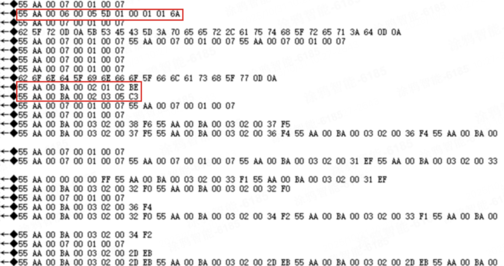
55 AA 00 06 00 05 5D 01 00 01 01 6A: The HID unlocking feature is enabled.55 AA 00 BA 00 02 01 02 BE: HID pairing was successful.55 AA 00 BA 00 02 03 05 C3: HID pairing was connected and verified.
-
MCU to Bluetooth LE device:
55 AA 00 07 00 05 5D 01 00 01 01 6B // Acknowledge HID unlocking enable command.
55 AA 00 BA 00 01 03 BD  // Query HID pairing status.
55 AA 00 BA 00 04 02 01 0A 01 CB  // Request to start sampling 10 RSSI values at the interval of 100 ms.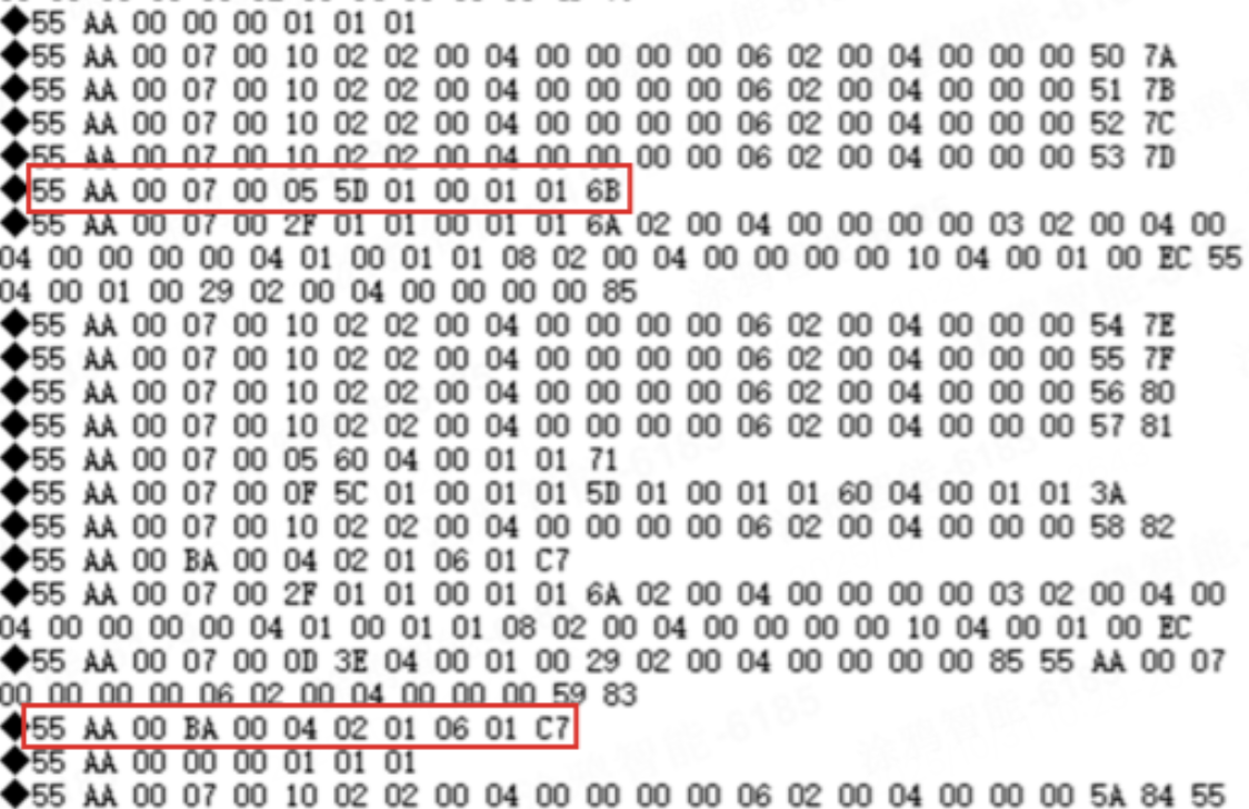
55 AA 00 07 00 05 5D 01 00 01 01 6B: MCU acknowledges DP 93 command.55 AA 00 BA 00 04 02 01 06 01 C7: Request RSSI values.
Considerations
- The device must send a corresponding DP response for every DP command received from the app.
- On the iOS platform, the Tuya app does not have permission to delete Bluetooth pairing information from the system. The app will prompt the user to navigate to the System Bluetooth settings to manually remove the existing pairing.
- During development, first assess the stability of RSSI values in the specific target environments (such as office vs. actual outdoor areas). Analyze the RSSI data profile before implementing the core logic.
- Implement strict conditional filtering on the sampled RSSI values to prevent invalid data from skewing the results. Ignore RSSI values ≤ -110 dBm. For example, discard values like -128 and -110.
Suggestions
During your implementation, please reference the following guidelines as needed:
- The acquired RSSI samples should first have their maximum and minimum values removed before calculating the average.
- Unlocking/locking threshold calculation: For certain implementations, when the MCU receives the DP 94 command, it stores the current RSSI value as the reference RSSI value. Unlocking threshold = Reference RSSI -
x, and locking threshold = Reference RSSI -y. Example: If the set reference RSSI is -53, the unlocking threshold = -56, and the locking threshold = -75. Note: Subtracting a value for the unlocking threshold enhances responsiveness. - If the required locking distance varies significantly across different phone models, implement separate logic paths based on DP 94 and DP 95, respectively.
The module only reports the raw RSSI value. The specific logic for triggering lock/unlock actions must be implemented by you based on the actual application scenarios and requirements.
Reference
-
For more information, see Serial Communication Protocol.
-
If you have any problems with TuyaOS development, you can post your questions in the Tuya Developer Forum.
Is this page helpful?
YesFeedbackIs this page helpful?
YesFeedback


