Three-Tier Serial Communication Protocol
Zigbee three-tier architecture
The Tuya Zigbee three-tier architecture is primarily used for concentrator devices, such as air conditioning concentrators and HVAC concentrators (hereinafter referred to as secondary devices). These devices communicate with the gateway via a Zigbee module, enabling remote access. Additionally, such devices can be connected to multiple tertiary devices, for example, terminal devices controlled via an RS-485 bus.
The overall architecture diagram is as follows:
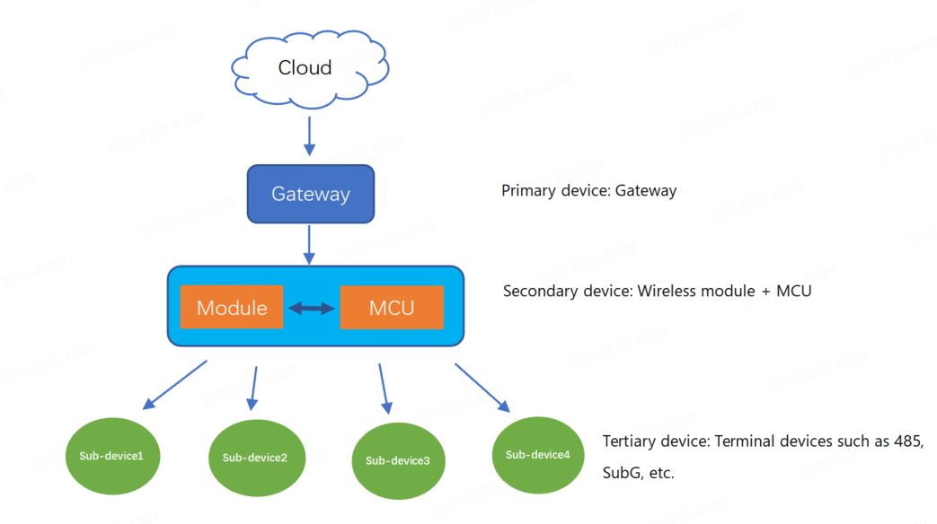
Each successfully registered tertiary sub-device will have its own control panel visible on the Tuya app, thereby enabling independent control.
Hardware connection
Both the Tuya Zigbee module and the MCU are powered by a DC 3.3V power supply. Communication between them is via a serial port, with the UART pins using standard logic. In the idle state, the TXD and RXD pins are both at a high level, with a low level as the start bit and a high level as the stop bit.
Serial communication
- Baud: 115200 bps
- Data bit: 8
- Parity check: none
- Stop bit: 1
- Data flow control: none
- Module TXD: PA5
- Module RXD: PA6
Frame format

The communication frame format is as follows:
| Field | Description |
|---|---|
| Frame head | It is fixed to 0x55AA. This field is used for frame format checking (numerical comparison, not character/string comparison). |
| Version | The version of the serial protocol, used for protocol updates or extensions. The current version is 0x02. This field is used for frame format checking (numerical comparison, not character/string comparison). |
| Sequence number (SEQ) | The sequence number for data transmission, cycling from 1 to 0xfff0. This field is represented as xx xx below. |
| Command ID | The ID of a command. Commands are continuously added and updated. This field is used for frame format checking (numerical comparison, not character/string comparison). |
| Data length | The payload length. |
| Data | The payload data. If the data length is 0, this field is omitted from the frame. |
| Checksum | Used for data verification. Start from the header, add up all the bytes, and then divide the sum by 256 to get the remainder. This field is represented as xx below. |
The length is determined by the length of a single packet transmitted by the Zigbee protocol. The transport layer reassembles the packet as it streams the data contents to the receiving application. The protocol defined by Tuya specifies the maximum packet length is 61 bytes.
Command ID
| Command | Sender | Description |
|---|---|---|
| 0x01 | Z | Query product information |
| 0x02 | Z | Sync module’s network status |
| 0x03 | M | Reset or pair module |
| 0x04 | M | Add tertiary sub-devices (Supports multiple PIDs) |
| 0x05 | M | Add tertiary sub-devices (Extendable PID, supports only a single PID with multiple addresses) |
| 0x06 | M | Test module’s RF functionality |
| 0x07 | Z | Query the statuses of all tertiary devices |
| 0x08 | Z | Send commands to a tertiary device |
| 0x09 | M | Report the tertiary device status |
| 0x0A | M | MCU deletes a tertiary sub-device |
| 0x0B | Z/M | Query the MCU’s version number |
| 0x0C | Z | Initiate OTA update |
| 0x0D | M | Request firmware updates over OTA |
| 0x0E | M | Report OTA update result |
| 0x10 | Z | Send commands to a secondary device |
| 0x11 | M | Report the secondary device status (passive) |
| 0x12 | M | Report the secondary device status (proactive) |
| 0x24 | M | Sync the time |
| 0x44 | M | Send multicast messages |
- M: Refers to the MCU, which sends a command to the Zigbee module.
- Z: Refers to the Zigbee module, which sends a command to the MCU.
Protocol description
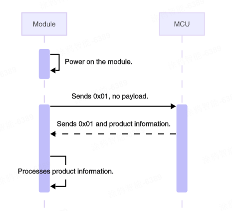
Query product information (0x01)
After powering on, the Zigbee module will proactively send a product information query command to the MCU to request the PID and version number information.
The MCU’s response containing the PID and version number should be the first command sent from the MCU to the module after the module powers on. The MCU must not send any other commands until it has responded to this query. If the MCU does not reply, or if the reply content format is incorrect, the module will repeat the query at 5-second intervals.
The module sends the following data.
| Field | Bytes | Description |
|---|---|---|
| Header | 2 | 0x55AA |
| Version | 1 | 0x02 |
| Sequence number | 2 | xx xx |
| Command | 1 | 0x01 |
| Data length | 2 | 0x0000 |
| Data | 0 | None |
| Checksum | 1 | xx |
Example: 55 AA 02 xx xx 01 00 00 xx.
The MCU returns the following data.
| Field | Bytes | Description |
|---|---|---|
| Header | 2 | 0x55AA |
| Version | 1 | 0x02 |
| Sequence number | 2 | xx xx |
| Command | 1 | 0x01 |
| Data length | 2 | N |
| Data | N | Product information, for example, {"p":"AIp08kLI", "v":"1.0.0"} |
| Checksum | 1 | xx |
Product information:
- p: The concentrator’s product ID (PID), generated by the Tuya Developer Platform.
- v: The version number of the MCU firmware, in
x.y.zformat.xranges from 0 to 3,yfrom 0 to 3, andzfrom 1 to 15. Therefore, the representable firmware version range is 0.0.1 to 3.3.15.
Example: 55 AA 02 xx xx 01 00 1C 7B 22 70 22 3A 22 41 49 70 30 38 6B 4C 49 22 2C 22 76 22 3A 22 31 2E 30 2E 30 22 7D xx.
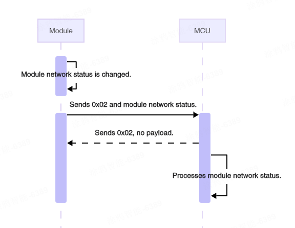
Sync module’s network status (0x02)
When the network status changes, the module will proactively send this command to the MCU.
The network status refers to the status of the Zigbee local network (not the internet connection status). This status does not change due to events such as a gateway power outage or the loss of a parent node.
The module sends the following data.
| Field | Bytes | Description |
|---|---|---|
| Header | 2 | 0x55AA |
| Version | 1 | 0x02 |
| Sequence number | 2 | xx xx |
| Command | 1 | 0x02 |
| Data length | 2 | 0x0001 |
| Data | 1 | The network status of the module |
| Checksum | 1 | xx |
The network status of the module
0x00: Not connected, such as when the device is powered on for the first time, fails to pair, or is removed from the mobile app.0x01: Connected, indicating that the device has been added to a Zigbee network.0x02: The module is in an abnormal network status. The module has not received the product information returned by the MCU.0x03: The device is being paired.
Example: 55 AA 02 xx xx 02 00 01 01 xx, indicating the module is connected.
The MCU returns the following data.
| Field | Bytes | Description |
|---|---|---|
| Header | 2 | 0x55AA |
| Version | 1 | 0x02 |
| Sequence number | 2 | xx xx |
| Command | 1 | 0x02 |
| Data length | 2 | 0x0000 |
| Data | 0 | None |
| Checksum | 1 | xx |
Example: 55 AA 02 xx xx 02 00 00 xx.
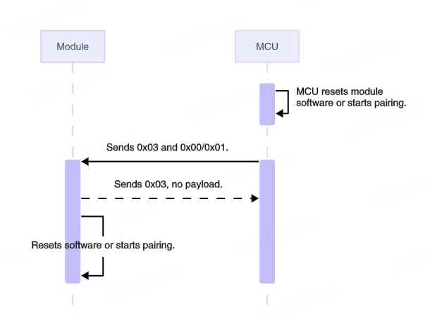
Reset or pair module (0x03)
The MCU can proactively send this command to the module to instruct the module to enter pairing mode and perform a software reset.
After the MCU returns the PID and version number, it can initiate the pairing process by sending the command 0x03 to the module. After the module receives the command, it responds to the MCU with 0x00 (not paired) and then 0x03 (being paired). Within the timeout period, the module returns 0x01 on successful pairing. Otherwise, it returns 0x00 (not paired).
The MCU sends the following data.
| Field | Bytes | Description |
|---|---|---|
| Header | 2 | 0x55AA |
| Version | 1 | 0x02 |
| Sequence number | 2 | xx xx |
| Command | 1 | 0x03 |
| Data length | 2 | 0x0001 |
| Data | 1 | 0x00: Reset the module. 0x01: The module starts pairing (Disconnect from the gateway first, then pairs). |
| Checksum | 1 | xx |
Example: 55 AA 02 xx xx 03 00 01 01 xx, indicating the module leaves the current network and joins a new one.
The module returns the following data.
| Field | Bytes | Description |
|---|---|---|
| Header | 2 | 0x55AA |
| Version | 1 | 0x02 |
| Sequence number | 2 | xx xx |
| Command | 1 | 0x03 |
| Data length | 2 | 0x0001 |
| Data | 1 | 0x00: Success |
| Checksum | 1 | xx |
Example: 55 AA 02 xx xx 03 00 01 00 xx.
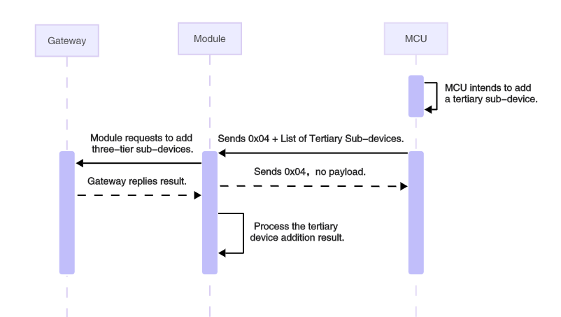
Add a tertiary device (0x04)
The MCU uses this command to add a tertiary sub-device. It must include the sub-device PID and address information. Multiple PIDs can be added simultaneously.
The addresses are managed and numbered by the MCU, and each tertiary sub-device address must be unique.
- This request can only be sent when the module is currently in a paired state.
- The module can add a maximum of 64 tertiary sub-devices.
The MCU sends the following data.
| Field | Bytes | Description |
|---|---|---|
| Header | 2 | 0x55AA |
| Version | 1 | 0x02 |
| Sequence number | 2 | xx xx |
| Command | 1 | 0x04 |
| Data length | 2 | N |
| Data | N | The list of tertiary sub-devices to add |
| Checksum | 1 | xx |
The list of tertiary sub-devices to add
| Field | Bytes | Description |
|---|---|---|
| The number of sub-devices to add | 1 | N: The maximum number of devices is 10 |
| Device 1 PID | 8 | The PID of the tertiary sub-device |
| Device 1 address | 2 | The address of the tertiary sub-device, managed by the MCU |
| Device 2 PID | 8 | - |
| Device 2 address | 2 | - |
| … | Fields added according to the number of devices | |
| Device 10 PID | 8 | - |
| Device 10 address | 2 | - |
Example: 55 AA 02 xx xx 04 00 0B 01 66 6A 35 66 71 65 67 39 00 01 xx
In this example, one tertiary sub-device is added. The sub-device PID is fj5fqeg9 and the address is 00 01.
The module returns the following data.
| Field | Bytes | Description |
|---|---|---|
| Header | 2 | 0x55AA |
| Version | 1 | 0x02 |
| Sequence number | 2 | xx xx |
| Command | 1 | 0x04 |
| Data length | 2 | 0x0000 |
| Data | 0 | None |
| Checksum | 1 | xx |
No response will be received if the device is not connected to the network or if more than 64 devices have been added.
Example: 55 AA 02 xx xx 04 00 00 xx.
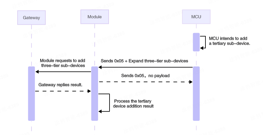
Add a tertiary device — extended command (0x05)
This protocol is an extended feature applicable when the PID length exceeds 8 bytes. The sub-device address is 2 bytes by default. The gateway will treat the address as an identifier, and each device address must be unique.
You can add only a single PID, but you are able to add multiple sub-device addresses.
- This request can only be sent when the module is currently in a paired state.
- The module can add a maximum of 64 tertiary sub-devices.
The MCU sends the following data.
| Field | Bytes | Description |
|---|---|---|
| Header | 2 | 0x55AA |
| Version | 1 | 0x02 |
| Sequence number | 2 | xx xx |
| Command | 1 | 0x05 |
| Data length | 2 | N |
| Data | N | The extended list of tertiary sub-devices to add |
| Checksum | 1 | xx |
The extended list of tertiary sub-devices to add
| Field | Bytes | Description |
|---|---|---|
| PID length | 1 | Fill in according to the actual PID length |
| PID | N | The PID of the tertiary sub-device |
| The number of sub-devices | 1 | The number of sub-devices to add (M) |
| Sub-device address | 2 × M | The list of the sub-device addresses to add |
Example: 55 AA 02 xx xx 05 00 14 10 78 76 72 6F 31 77 30 77 6A 6E 64 67 73 77 78 64 01 00 01 xx.
In this example, one tertiary sub-device with a PID length of 16 is added. The sub-device address is 00 01.
The module returns the following data.
| Field | Bytes | Description |
|---|---|---|
| Header | 2 | 0x55AA |
| Version | 1 | 0x02 |
| Sequence number | 2 | xx xx |
| Command | 1 | 0x05 |
| Data length | 2 | 0x0000 |
| Data | 0 | None |
| Checksum | 1 | xx |
No response will be received if the device is not connected to the network or if more than 64 devices have been added.
Example: 55 AA 02 xx xx 05 00 00 xx.
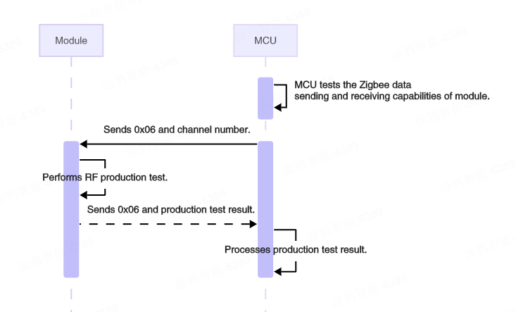
Test module’s RF functionality (0x06)
The MCU can proactively send this command to the module to initiate RF testing, verifying the module’s capability to send and receive RF data correctly.
Before starting RF testing, you must prepare a production test dongle and configure it to RF mode. For detailed instructions, refer to Set Up the Zigbee Dongle.
Once the RF test is activated upon receiving this command, the module sends 100 raw data packets in a specific format, with 20-millisecond intervals between each packet. The dongle returns each received packet in a loopback manner. If the data packet received by the module matches the content of the raw data packet it sent itself, it is considered to have successfully received a loopback packet.
After the RF test concludes, the module sends the RF test results (including the number of valid received packets) to the MCU, enabling the MCU to evaluate the module’s transmission and reception performance. However, this command does not check for signal strength.
RF production testing must be performed in an unpaired state. Upon test completion, the module must be restarted to resume normal operation.
The MCU sends the following data.
| Field | Bytes | Description |
|---|---|---|
| Header | 2 | 0x55AA |
| Version | 1 | 0x02 |
| Sequence number | 2 | xx xx |
| Command | 1 | 0x06 |
| Data length | 2 | 0x0001 |
| Data | 1 | The channel number ranging from 11 to 26. Default: Channel 11. |
| Checksum | 1 | xx |
- The channel number must be consistent with the channel number configured on the dongle.
- Do not perform RF tests on multiple devices simultaneously on the same channel, as this will cause mutual interference.
Example: 55 AA 02 xx xx 06 00 01 0B xx, conducting an RF test on channel 11.
The module returns the following data.
| Field | Bytes | Description |
|---|---|---|
| Header | 2 | 0x55AA |
| Version | 1 | 0x02 |
| Sequence number | 2 | xx xx |
| Command | 1 | 0x06 |
| Data length | 2 | 0x0002 |
| Data | 2 | RF test results |
| Checksum | 1 | xx |
RF test results (status: 1 byte, number of loopback packets: 1 byte):
- Data[0] = 0x00, indicating the test failed. Data[1]= 0x00, indicating the loopback packet was not received.
- Data[0] = 0x01, indicating the test passed. Data[1] = Number of loopback packets (1–100).
Example: 55 AA 02 xx xx 06 00 02 01 62 xx, indicating the RF test passed, with 98 out of 100 data packets looped back.
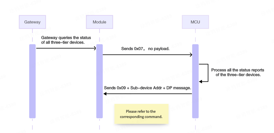
Query the statuses of all tertiary devices (0x07)
After a successful pairing or after a gateway restart, the gateway will send a command to the module to synchronize the DP statuses of sub-devices. The module then sends this command (0x07) to notify the MCU.
Upon receiving this command, the MCU needs to report the statuses of the tertiary sub-devices. The reported data must not exceed 62 bytes. If the DP data is too long, it must be reported in multiple packets.
The module sends the following data.
| Field | Bytes | Description |
|---|---|---|
| Header | 2 | 0x55AA |
| Version | 1 | 0x02 |
| Sequence number | 2 | xx xx |
| Command | 1 | 0x07 |
| Data length | 2 | 0x0000 |
| Data | 0 | None |
| Checksum | 1 | xx |
Example: 55 AA 02 xx xx 07 00 00 xx.
Upon receiving this command, the MCU does not need to send a response. It simply reports the sub-device status directly via command 0x09.
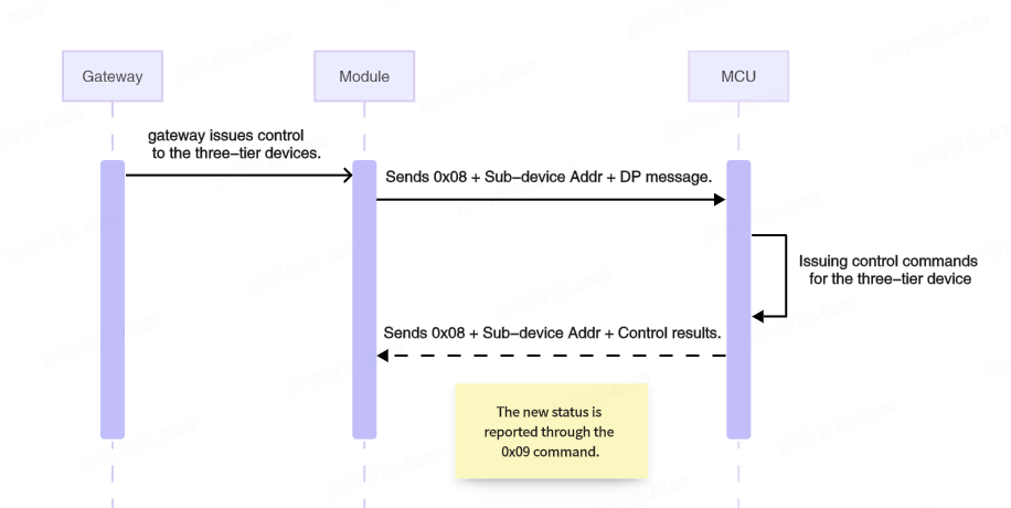
Send commands to a tertiary device (0x08)
The gateway sends control commands to tertiary sub-devices. The module transparently transmits the tertiary sub-device address and the DP message to the MCU.
The module sends the following data.
| Field | Bytes | Description |
|---|---|---|
| Header | 2 | 0x55AA |
| Version | 1 | 0x02 |
| Sequence number | 2 | xx xx |
| Command | 1 | 0x08 |
| Data length | 2 | N: Depends on the DP message type and count + the length of the sub-device address |
| Data | N | Sub-device address (2 bytes) + DP message |
| Checksum | 1 | xx |
DP message format:
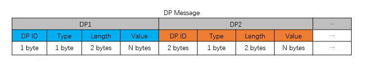
A single DP message may contain multiple pieces of DP data. The format for each piece of DP data is as follows:
- DP ID: The ID of a DP defined on the Tuya Developer Platform.
- Type: The date type of DP. Some data types have a fixed length.
- Length: The length of the data in the
Valuefield. - Value: The payload.
The format of type:
| Type | DP type | Data length | Description |
|---|---|---|---|
| 0x00 | Raw | N | Raw data type in hex format, with customizable bytes. |
| 0x01 | Bool | 1 | Boolean data type. Valid values include 0x00 and 0x01. |
| 0x02 | Value | 4 | Value data type, for example, 1, 23, and 104. |
| 0x03 | String | N | Custom string. |
| 0x04 | Enum | 1 | Enum data type, ranging from 0 to 255. |
| 0x05 | Bitmap | 1/2/4 | Bitmap data type, used to report error codes. |
Example: 55 AA 02 xx xx 08 00 07 00 01 03 01 00 01 01 xx, indicating the module received a DP message with data for one DP, as follows.
- Tertiary sub-device address:
00 01 - DP ID:
03 - Type:
01 - Length:
00 01 - Value:
01
The MCU returns the following data.
| Field | Bytes | Description |
|---|---|---|
| Header | 2 | 0x55AA |
| Version | 1 | 0x02 |
| Sequence number | 2 | xx xx |
| Command | 1 | 0x08 |
| Data length | 2 | 0x0000 |
| Data | 0 | None |
| Checksum | 1 | xx |
Example: 55 AA 02 xx xx 08 00 00 xx.
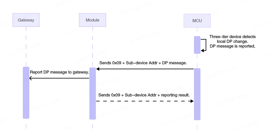
Report the tertiary device status (0x09)
When the status of a tertiary sub-device changes, it can be reported via this command to synchronize the device status on the app.
- When the MCU receives the 0x08 command from the gateway and executes the specified actions, it needs to report the new DP statuses resulting from the execution to the gateway (only the DP statuses of the executed actions need to be reported).
- When the MCU receives the 0x07 command from the module, it needs to report all reportable DP statuses of the device.
- Upon receiving this command, the module will immediately reply with an acknowledgement.
- It can contain multiple DP data units. The maximum data length for the DP message is 59 bytes.
The MCU sends the following data.
| Field | Bytes | Description |
|---|---|---|
| Header | 2 | 0x55AA |
| Version | 1 | 0x02 |
| Sequence number | 2 | xx xx |
| Command | 1 | 0x09 |
| Data length | 2 | N: Depends on the DP message type and count + the length of the sub-device address |
| Data | N | Sub-device address (2 bytes) + DP message |
| Checksum | 1 | xx |
This example shows an MCU reporting DP data for a tertiary sub-device.
- Tertiary sub-device address:
00 01 - DP ID:
03 - DP type:
01 - DP length:
00 01 - DP value:
01
The module returns the following data.
| Field | Bytes | Description |
|---|---|---|
| Header | 2 | 0x55AA |
| Version | 1 | 0x02 |
| Sequence number | 2 | xx xx |
| Command | 1 | 0x09 |
| Data length | 2 | 0x0003 |
| Data | 3 | Sub-device address (2 bytes) + result (1 byte) |
| Checksum | 1 | xx |
Result:
0x00: Success0x01: Failure
Example: 55 AA 02 xx xx 09 00 03 00 01 00 xx.
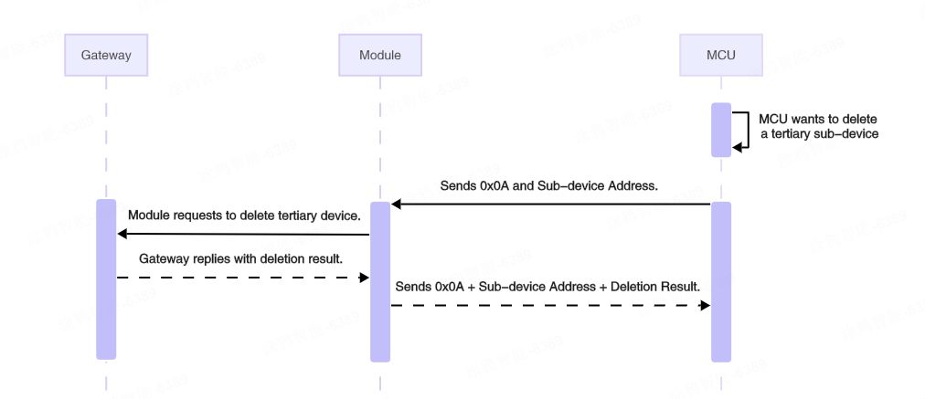
MCU deletes a tertiary sub-device (0x0A)
The MCU can proactively send this command to remove a specified tertiary sub-device.
The MCU sends the following data.
| Field | Bytes | Description |
|---|---|---|
| Header | 2 | 0x55AA |
| Version | 1 | 0x02 |
| Sequence number | 2 | xx xx |
| Command | 1 | 0x0A |
| Data length | 2 | 0x0002 |
| Data | 2 | The address of the sub-device to be deleted |
| Checksum | 1 | xx |
Example: 55 AA 02 xx xx 0A 00 02 00 01 xx, indicating to delete a tertiary sub-device with the sub-device address 00 01.
The module returns the following data.
| Field | Bytes | Description |
|---|---|---|
| Header | 2 | 0x55AA |
| Version | 1 | 0x02 |
| Sequence number | 2 | xx xx |
| Command | 1 | 0x0A |
| Data length | 2 | 0x0003 |
| Data | 3 | Sub-device address (2 bytes) + result (1 byte) |
| Checksum | 1 | xx |
Result:
0x00: Success0x01: Failure
Example: 55 AA 02 xx xx 0A 00 03 00 01 00 xx.
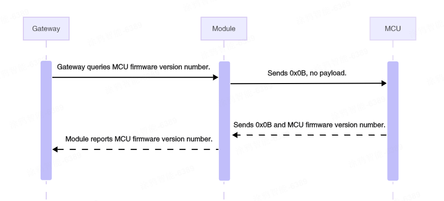
Query the MCU’s version number (0x0B)
When the module receives a query command from the gateway, it will proactively send this command to the MCU. The MCU needs to reply with its current firmware version number. This is used, for example, to determine whether to initiate an OTA update.
The MCU can also proactively send its current firmware version number to the module using this command in scenarios such as successful module pairing or after a successful OTA update of the MCU firmware.
After the module obtains the current firmware version number from the MCU, it will synchronize this version number to the cloud for display purposes or for OTA update check.
The module sends the following data.
| Field | Bytes | Description |
|---|---|---|
| Header | 2 | 0x55AA |
| Version | 1 | 0x02 |
| Sequence number | 2 | xx xx |
| Command | 1 | 0x0B |
| Data length | 2 | 0x0000 |
| Data | 0 | None |
| Checksum | 1 | xx |
Example: 55 AA 02 xx xx 0B 00 00 xx, querying the current version number of the MCU.
The MCU returns the following data.
| Field | Bytes | Description |
|---|---|---|
| Header | 2 | 0x55AA |
| Version | 1 | 0x02 |
| Sequence number | 2 | xx xx |
| Command | 1 | 0x0B |
| Data length | 2 | 0x0001 |
| Data | 1 | The MCU firmware version number (1 byte) |
| Checksum | 1 | xx |
The MCU firmware version number is 1 byte. Its 8 bits are interpreted in the binary format xx.yy.zzzz. For example, 0x40 in binary is 01 00 0000, which represents version 1.0.0. Due to the 1-byte limitation, the maximum version number possible is 3.3.15.
Example: 55 AA 02 xx xx 0B 00 01 53 xx, indicating the current version number is 0x53, which in binary is 01 01 0011, corresponding to version 1.1.3.
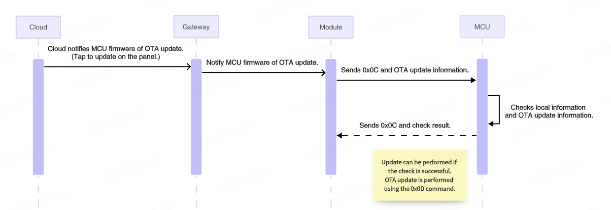
Initiate OTA update (0x0C)
If a product has the MCU OTA update feature configured and the push service enabled on the Tuya Developer Platform, the mobile app will notify users or automatically initiate an update when an update is available. After the MCU firmware update is initiated on the panel, the gateway notifies the module.
Upon receiving the notification, the module sends this command to the MCU to notify it to prepare for the OTA update.
The module sends the following data.
| Field | Bytes | Description |
|---|---|---|
| Header | 2 | 0x55AA |
| Version | 1 | 0x02 |
| Sequence number | 2 | xx xx |
| Command | 1 | 0x0C |
| Data length | 2 | 0x0011 |
| Data | 17 | PID (8 bytes) + new firmware version number (1 byte) + firmware size (4 bytes) + firmware checksum (4 bytes) |
| Checksum | 1 | xx |
- PID (8 bytes): The PID of the current device, for example,
AIp08kLI. - New firmware version number (1 byte): For example,
0x41indicates version 1.0.1. - Firmware size (4 bytes): Measured in bytes.
- Firmware checksum (4 bytes): The checksum of the entire firmware from the first byte.
Example: 55 AA 02 xx xx 0C 00 11 41 49 70 30 38 6B 4C 49 41 00 00 78 00 30 31 32 33 XX, an OTA update notification with the following content:
- PID:
41 49 70 30 38 6B 4C 49, which isAIp08kLI. - New firmware version number:
0x41, which is version 1.0.1. - Firmware size:
0x00007800, which is 30 KB. - Firmware checksum: 0x30313233
.
The MCU returns the following data.
| Field | Bytes | Description |
|---|---|---|
| Header | 2 | 0x55AA |
| Version | 1 | 0x02 |
| Sequence number | 2 | xx xx |
| Command | 1 | 0x0C |
| Data length | 2 | 0x0001 |
| Data | 1 | 0x00: Failure. 0x01: Success. |
| Checksum | 1 | xx |
Example: 55 AA 02 xx xx 0C 00 01 01 xx.
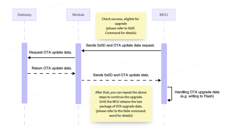
Request firmware updates over OTA (0x0D)
After the MCU receives the OTA update notification (0x0C) command and confirms the OTA update information is correct, it can send the command to the module. This instructs the module to request the OTA file from the gateway (that is, to start downloading the OTA file).
The device manages the download process by sending a file request that includes the data offset and packet size. After receiving the request from the device, the gateway returns the packet offset and update data. This command is initiated by the MCU and forwarded to the gateway by the module upon receipt. Due to the single-frame length limitation of the Zigbee wireless protocol, plus necessary overhead, each data packet requested by the MCU cannot exceed 48 bytes. This process continues until all data packets have been requested.
The MCU sends the following data.
| Field | Bytes | Description |
|---|---|---|
| Header | 2 | 0x55AA |
| Version | 1 | 0x02 |
| Sequence number | 2 | xx xx |
| Command | 1 | 0x0D |
| Data length | 2 | 0x000E |
| Data | 14 | PID (8 bytes) + new firmware version number (1 byte) + packet offset (4 bytes) + packet size (1 byte) |
| Checksum | 1 | xx |
- PID (8 bytes): The PID of the current device, for example,
AIp08kLI. - New firmware version number (1 byte): For example,
0x41indicates version 1.0.1. - Packet offset (4 bytes): The offset of the requested data in the OTA file, in bytes.
- Packet size (1 byte): The size of the requested packet, in bytes, up to 48 bytes.
Example: 55 AA 02 xx xx 0D 00 0E 41 49 70 30 38 6B 4C 49 41 00 00 10 00 30 XX, requesting a 48-byte packet starting from the address 4096.
- PID:
0x41 49 70 30 38 6B 4C 49, which isAIp08kLI. - New firmware version number:
0x41, which is version 1.0.1. - Packet offset:
0x00001000, indicating an offset address of 4096. - Packet size:
0x30, requesting 48 bytes of data.
The module returns the following data.
| Field | Bytes | Description |
|---|---|---|
| Header | 2 | 0x55AA |
| Version | 1 | 0x02 |
| Sequence number | 2 | xx xx |
| Command | 1 | 0x0D |
| Data length | 2 | N |
| Data | N | Result (1 byte) + PID (8 bytes) + new firmware version number (1 byte) + packet offset (4 bytes) + payload |
| Checksum | 1 | xx |
-
The returned result.
0x00: Success0x01: Failure If the request fails, the subsequent data does not exist.
-
PID (8 bytes): The PID of the current device, for example,
AIp08kLI. -
New firmware version number (1 byte): For example,
0x41indicates version 1.0.1. -
Packet offset (4 bytes): The offset of the requested data in the OTA file, in bytes.
-
Payload (N bytes): The actual data.
Example: 55 AA 02 xx xx 0D xx xx 00 41 49 70 30 38 6b 4c 49 41 00 00 00 32 … xx, indicating a successful request (payload represented by ellipsis).
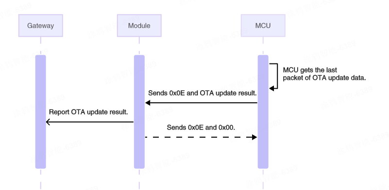
Report update result (0x0E)
After the MCU OTA update is completed, the MCU can proactively send this command to the module to instruct it to report the OTA update result to the gateway. The result should be reported regardless of whether the update succeeded or failed.
The MCU sends the following data.
| Field | Bytes | Description |
|---|---|---|
| Header | 2 | 0x55AA |
| Version | 1 | 0x02 |
| Sequence number | 2 | xx xx |
| Command | 1 | 0x0E |
| Data length | 2 | 0x000A |
| Data | 10 | Result (1 byte) + PID (8 bytes) + new firmware version number (1 byte) |
| Checksum | 1 | xx |
-
The update result (1 byte):
0x00: Success0x01: Failure
Example: 55 AA 02 xx xx 0E 00 0A 00 41 49 70 30 38 6B 4C 49 41 xx, indicating the MCU OTA update succeeded.
- Update result:
0x00indicates success. - PID:
0x41 49 70 30 38 6B 4C 49, which isAIp08kLI. - New firmware version number:
0x41, which is version 1.0.1.
The module returns the following data.
| Field | Bytes | Description |
|---|---|---|
| Header | 2 | 0x55AA |
| Version | 1 | 0x02 |
| Sequence number | 2 | xx xx |
| Command | 1 | 0x0E |
| Data length | 2 | 0x0001 |
| Data | 1 | 0x00: Reported successfully. 0x01: Failed to report. |
| Checksum | 1 | xx |
Example: 55 AA 02 xx xx 0E 00 01 00 xx.
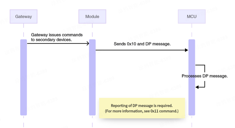
Send commands to a secondary device (0x10)
The Zigbee module can send commands to the secondary device’s MCU.
- All available data types, except for the raw type, are object types.
- The object types allow sending several control commands in a single packet.
- The raw type supports sending only a single command.
- A packet cannot contain both raw data and object data.
- The 0x10 command sending utilizes an asynchronous processing protocol, corresponding to 0x11 status reporting (passive) and 0x12 status reporting (proactive).
The module sends the following data.
| Field | Bytes | Description |
|---|---|---|
| Header | 2 | 0x55AA |
| Version | 1 | 0x02 |
| Sequence number | 2 | xx xx |
| Command | 1 | 0x10 |
| Data length | 2 | N |
| Data | N | DP message format |
| Checksum | 1 | xx |
For data segments, refer to the DP message format for command 0x08.
Example: 55 AA 02 xx xx 10 00 05 03 01 00 01 01 xx, indicating the module received a DP message with data for one DP of the secondary device, as follows.
- DP ID:
03 - Type:
01 - Length:
00 01 - Value:
01
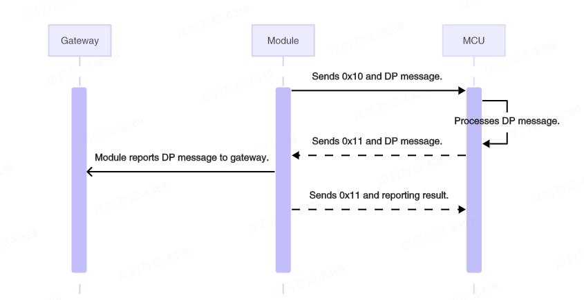
Report the secondary device status (passive) (0x11)
After the MCU receives and correctly executes a command from the module, it reports the changed DP status to the module.
- This is a synchronous command. The module should acknowledge the receipt of the packet on receiving it.
- Status reporting (passive) can include multiple object type commands.
- A packet cannot contain both raw data and object data.
- Whether passive reporting is successful does not indicate whether the data has reached the gateway.
The MCU sends the following data.
| Field | Bytes | Description |
|---|---|---|
| Header | 2 | 0x55AA |
| Version | 1 | 0x02 |
| Sequence number | 2 | xx xx |
| Command | 1 | 0x11 |
| Data length | 2 | N |
| Data | N | DP message format |
| Checksum | 1 | xx |
For data segments, refer to the DP message format for command 0x08.
Example: 55 AA 02 xx xx 11 00 05 03 01 00 01 01 xx, indicating the MCU reports DP messages passively.
- DP ID:
03 - Type:
01 - Length:
00 01 - Value:
01
The module returns the following data.
| Field | Bytes | Description |
|---|---|---|
| Header | 2 | 0x55AA |
| Version | 1 | 0x02 |
| Sequence number | 2 | xx xx |
| Command | 1 | 0x11 |
| Data length | 2 | 0x0001 |
| Data | 1 | 0x00: Status reporting failed 0x01: Status reporting was successful. |
| Checksum | 1 | xx |
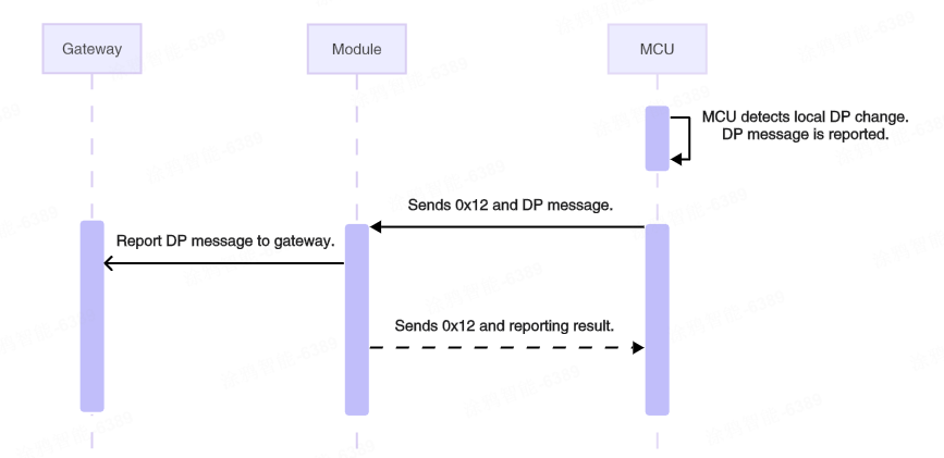
Report the secondary device status (proactive) (0x12)
When the MCU proactively detects status changes of DPs, it reports the changed DP status to the module.
- Typically, the MCU reports only the changed DP status.
- Status reporting (proactive) is an asynchronous processing protocol. When the module receives DP data from the MCU via
0x12, the module reports the data to the Zigbee gateway. Upon receiving a response from the Zigbee gateway, the module will return the status to the MCU.- If the gateway returns a response, the module will asynchronously return a success status to the MCU.
- If the gateway does not return a response, the module will return a failure status to the MCU after a waiting timeout.
- If the module is not paired, it should immediately respond to the MCU with failure.
- The MCU can check if the connection between the module and the gateway works fine based on the module’s response.
- All available data types, except for the raw type, are object types.
- The object type supports reporting multiple commands, with a maximum of 10 DP data items.
- The raw type supports reporting only a single command.
- DP data reported via command
0x12will trigger linkages.
The MCU sends the following data.
| Field | Bytes | Description |
|---|---|---|
| Header | 2 | 0x55AA |
| Version | 1 | 0x02 |
| Sequence number | 2 | xx xx |
| Command | 1 | 0x12 |
| Data length | 2 | N |
| Data | N | DP message format |
| Checksum | 1 | xx |
For data segments, refer to the DP message format for command 0x08.
Example: 55 AA 02 xx xx 12 00 05 03 01 00 01 01 xx, indicating the MCU reports DP messages proactively.
- DP ID:
03 - Type:
01 - Length:
00 01 - Value:
01
The module returns the following data.
| Field | Bytes | Description |
|---|---|---|
| Header | 2 | 0x55AA |
| Version | 1 | 0x02 |
| Sequence number | 2 | xx xx |
| Command | 1 | 0x12 |
| Data length | 2 | 0x0001 |
| Data | 1 | 0x00: Status reporting failed 0x01: Status reporting was successful. |
| Checksum | 1 | xx |
Example: 55 AA 02 xx xx 12 00 01 01 xx.
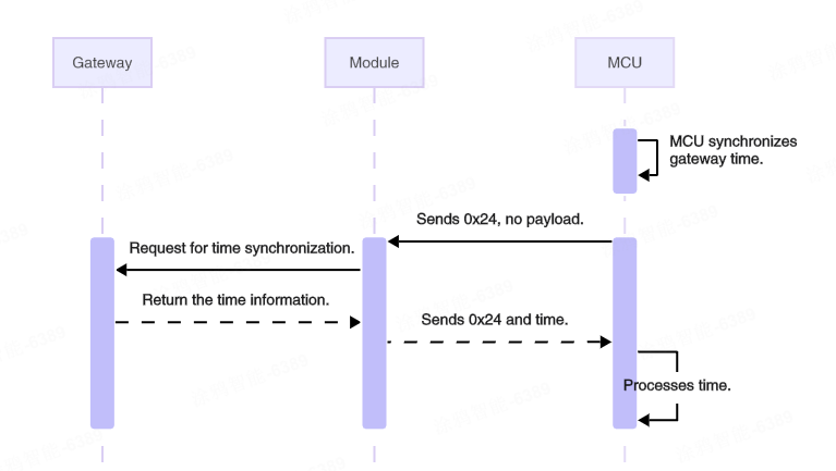
Sync time (0x24)
The MCU can proactively send this command to the module to request time information from the gateway.
After the gateway replies to the module, the module will notify the MCU of the time information via this command.
The MCU sends the following data.
| Field | Bytes | Description |
|---|---|---|
| Header | 2 | 0x55AA |
| Version | 1 | 0x02 |
| Sequence number | 2 | xx xx |
| Command | 1 | 0x24 |
| Data length | 2 | 0x0000 |
| Data | 0 | None |
| Checksum | 1 | xx |
Example: 55 AA 02 xx xx 24 00 00 xx, indicating the MCU initiates a time sync request.
The module returns the following data.
| Field | Bytes | Description |
|---|---|---|
| Header | 2 | 0x55AA |
| Version | 1 | 0x02 |
| Sequence number | 2 | xx xx |
| Command | 1 | 0x24 |
| Data length | 2 | 0x0008 |
| Data | 8 | Unix timestamp (4 bytes) + local timestamp (4 bytes) |
| Checksum | 1 | xx |
- Unix timestamp: The number of seconds that have elapsed since January 1, 1970, at 00:00:00 Greenwich Mean Time (GMT).
- Local timestamp: Calculated by adding the time zone offset and daylight saving time (DST) (if applicable) to the Unix timestamp. Local time typically prevails.
Example: 55 AA 02 xx xx 24 00 08 66 45 DB F0 66 46 4C 70 xx.
- Unix time:
0x6645DBF0. - Local time:
0x66464C70.
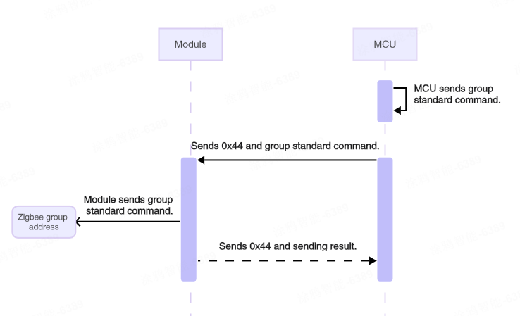
Send multicast messages (0x44)
The MCU can proactively send this command to the module, instructing it to send standard commands to a group via multicast, thereby controlling devices within the group that support standard commands.
The standard commands here are defined by the Zigbee 3.0 specification and typically follow the format: cluster ID + command ID + payload.
The multicast message is only used to instruct a group of devices to perform the specified action. Devices need to report status separately.
The MCU sends the following data.
| Field | Bytes | Description |
|---|---|---|
| Header | 2 | 0x55AA |
| Version | 1 | 0x02 |
| Sequence number | 2 | xx xx |
| Command | 1 | 0x44 |
| Data length | 2 | N |
| Data | N | Group ID (2) + standard command format (cluster ID + command ID + payload) |
| Checksum | 1 | xx |
Format of standard commands:
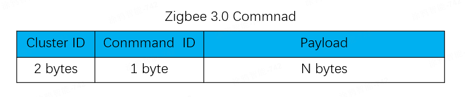
For payload details of standard commands, see the official Zigbee Cluster Library Specification R8. This specification is provided by the CSA and may be updated in the future.
Example: 55 AA 02 xx xx 44 00 05 2A 08 00 06 01 xx, sending a standard command via multicast with the following content.
- Group ID:
0x2A08 - Cluster ID:
0x0006 (onoff cluster) - Command ID:
0x01 (on) - Payload:
null
The module returns the following data.
| Field | Bytes | Description |
|---|---|---|
| Header | 2 | 0x55AA |
| Version | 1 | 0x02 |
| Sequence number | 2 | xx xx |
| Command | 1 | 0x44 |
| Data length | 2 | 0x0001 |
| Data | 1 | 0x00: Failure. 0x01: Success. |
| Checksum | 1 | xx |
Example: 55 AA 02 xx xx 44 00 01 01 xx, indicating the standard command is sent successfully via multicast.
Version history
| Changes | Date | Description |
|---|---|---|
| Optimized | 2026-02-24 | Optimized the document and added protocol interaction diagrams. |
| Modified | 2024-06-06 |
|
| Optimized | 2024-06-03 | Fixed errors and added explanations. |
| Optimized | 2022-12-15 | Optimized the document. |
| Created | 2022-11-30 | Created the document. |
Is this page helpful?
YesFeedbackIs this page helpful?
YesFeedback


