VCT1 Offline Voice Module Datasheet
Product overview
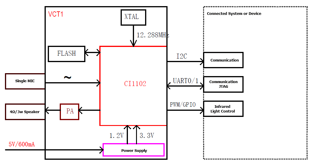
VCT1 is a high-performance and low-cost offline voice recognition module that Tuya has developed. It consists of a highly integrated voice recognition chip CI1102, an external flash memory, an audio amplifier, and a peripheral power chip. The module is built in with the Neural Network Processing Unit BNPU which supports large-scale local voice recognition. It can be made into various types of smart voice solutions with a built-in CPU.
The architecture of the module is shown below:
Features
- Small size, suitable to be integrated into various overall units
- Low power, ≤150mW during operation, applicable to products that have the energy consumption requirements and battery-powered products
- Low cost and high-cost performance. VCT1 is a dedicated voice recognition module for the Artificial Neural Network (ANN) in the industry.
- High performance. The single microphone solution achieves a super high recognition rate, super long distance recognition, single-microphone noise reduction, and single-microphone echo cancellation.
- Good expansibility. Extend IoT modules (such as Wi-Fi, Zigbee and Bluetooth LE) through I2C to achieve networking.
- Rich interfaces including UART, PWM, and ADC.
Applications
- Smart home products that can be controlled independently
- Voice interfaces for hotel and real estate
- Entertainment and toys
Module interfaces
Dimensions and footprint
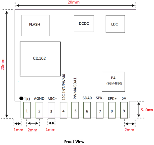
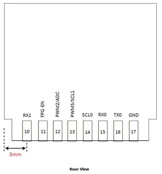
VCT1 has 2 lines of pins, 17 pins in total, with a spacing of 2.0 mm.
The VCT1 dimensions are 20 mm (L)×20 mm (W) ×3 mm (H), which are shown below:
Interface definitions
| Pin number | Pin name | Type | Driving capability | Default state when powered on | Function |
|---|---|---|---|---|---|
| 1 | TX1 | I/O, T+U | 4mA | IN, T+U | 1. UART1_TX; 2.GPIO 23 |
| 2 | AGND | P | Analog ground | ||
| 3 | MIC+ | - | - | - | Microphone positive |
| 4 | I2C-INT | I/O, T+U | 4 mA | IN, T+U | 1. GPIO 37; 2. PWM 0; 3. ADC 0_IN |
| 5 | PWM4 | I/O | 4 mA | IN, T+D | 1. PWM 4; 2. GPIO 19; 3. I2C1_SDA |
| 6 | SDA0 | I/O, T+D | 4 mA | IN, T+D | 1. I2C0-SDA; and 2. GPIO 2 |
| 7 | SPK- | - | - | - | Speaker |
| 8 | SPK+ | - | - | - | Speaker |
| 9 | 5V | P | - | - | Power supply of 5V |
| 10 | RX1 | I/O, T+U | 4 mA | IN, T+U | 1. UART1_RX; and 2. GPIO 24 |
| 11 | PG_EN | I/O, T+D | 4 mA | - | 1. FLASH_PG_EN, enter the UART upgrade mode when the module is pulled to 3.3V; 2. GPIO 31 |
| 12 | PWM2 | I/O | 4 mA | IN, T+D | 1. PWM 2; 2. GPIO 35; 3. ADC 2 |
| 13 | PWM5 | I/O | 4 mA | IN, T+D | 1. PWM 5; 2. GPIO 20; 3. I2C1_SCL |
| 14 | SCL0 | I/O, T+D | 4 mA | IN, T+D | 1. I2C0-SDA; and 2. GPIO 3 |
| 15 | RX0 | I/O, T+U | 4 mA | IN, T+U | 1. UART0_RX; and 2. GPIO 1 |
| 16 | TX0 | I/O, T+U | 4 mA | IN, T+U | 1. UART0_TX; and 2. GPIO 0 |
| 17 | GND | P | Signal ground |
Reference for circuit design
Power supply
The power amplification chip adopts the power supply of 5V, which requires a rated current of 600 mA.
PWM
The module has 3 outputs of PWM signals
ESD
Because there’s no ESD component in the module, external ESD components are required, such as a microphone, speaker, UART interface, and power supply.
GPIO
All I/O interfaces of the module can be configured as GPIO. All GPIOs are at the 3.3V level.
Parameters
Electrical feature parameters
| Parameter | Condition | Minimum value | Typical value | Maximum value | Unit | Remarks |
|---|---|---|---|---|---|---|
| Supply voltage | 4.5 | 5 | 5.5 | V | The typical supply voltage is 5V, and the module will be damaged if the voltage exceeds 5.5V | |
| Current in broadcast state (largest volume) | 4Ω 2W speaker | / | / | 300 | mA | When the module broadcast in the largest volume, the instant current at 5V can be up to 300 mA, and sometimes can be up to 500mA for network videos, so driving capability of the power supply should be 600 mA in principle. |
| Operating current | / | 40 | / | mA | The typical value is obtained in mute state, and the maximum value is obtained in recognition and broadcast state. | |
| Current in monitoring state in the quiet environment | 5V power supply | / | 29 | / | mA | / |
| Voltage of I/O interface | 3 | 3.3 | 3.6 | V | / |
Note: The speaker with the resistance of 4 Ω and power of less than 1.5W is highly recommended.
Temperature and humidity parameters
| Parameter | Minimum value | Typical value | Maximum value | Unit |
|---|---|---|---|---|
| Operating temperature | 0 | 25 | 85 | °C |
| Storage temperature | -20 | 25 | 100 | °C |
| Soldering temperature | / | 220 | 245 | °C |
| Storage RH | 0% | / | 5% | RH |
Note: The module needs to be stored in vacuum. You’d better use up all modules within 4 hours after they are unpacked. If there are modules unused within 4 hours, they must be placed at the 5%RH drying cupboard and soldered within 48 hours. If modules are exposed to air for over 4 hours, they need to be baked before being used.
Production instructions
- For the Tuya in-line module, wave soldering is most preferred and manual soldering is less preferred. After being unpacked, the module must be soldered within 24 hours. Otherwise, it must be put into the drying cupboard where the RH is not greater than 10%; or it needs to be packaged under vacuum again and record the exposure time (the total exposure time cannot exceed 168 hours).
- Wave soldering devices and materials:
- Wave soldering equipment
- Wave soldering fixture
- Constant-temperature soldering iron
- Tin bar, tin wire, and flux
- Thermal profiler
- Baking devices:
- Cabinet oven
- Anti-electrostatic and heat-resistant trays
- Anti-electrostatic and heat-resistant gloves
- The module needs to be baked in the following cases:
- The packaging bag is damaged before unpacking.
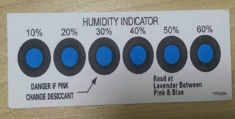
- There is no humidity indicator card (HIC) in the packaging bag.
- After unpacking, circles of 10% and above on the HIC become pink.
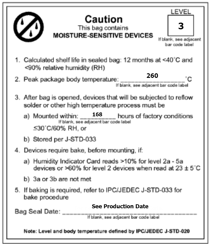
- The total exposure time has lasted for over 168 hours since unpacking.
- More than 12 months have passed since the sealing of the bag.
- Baking settings:
- Temperature: 60°C and ≤ 5% RH for reel package and 125°C and ≤5% RH for tray package (please use the heat-resistant tray rather than plastic container)
- Time: 48 hours for reel package and 12 hours for tray package
- Alarm temperature: 65°C for reel package and 135°C for tray package
- Production-ready temperature after natural cooling: < 36°C
- Re-baking situation: If a module remains unused for over 168 hours after being baked, it needs to be baked again.
- If a batch of modules is not baked within 168 hours, do not use the wave soldering to solder them. Because these modules are Level-3 moisture-sensitive devices, they are very likely to get damp when exposed beyond the allowable time. In this case, if they are soldered at high temperatures, it may result in device failure or poor soldering.
- In the whole production process, take electrostatic discharge (ESD) protective measures.
- To guarantee the quality of products, you must pay attention to the following items: The amount of soldering flux, the height of the wave peak, whether the tin slag and copper content in the wave soldering tank exceed standards, whether the window and thickness of the wave soldering fixture are appropriate, and whether the wave soldering oven temperature curve is appropriate.
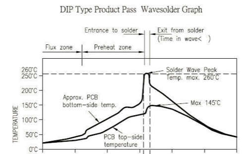
Recommended oven temperature curve and temperature
Set oven temperatures according to the following temperature curve of wave soldering. The peak temperature is 260°C±5°C.
Recommended soldering temperature:
| Suggestions on oven temperature curve of wave soldering | Suggestions on manual soldering temperature | ||
|---|---|---|---|
| Preheat temperature | 80 to 130 °C | Soldering temperature | 360±20°C |
| Preheat time | 75 to 100s | Soldering time | <3s/point |
| Peak contact time | 3 to 5s | NA | NA |
| Temperature of tin cylinder | 260±5°C | NA | NA |
| Ramp-up slope | ≤2°C/s | NA | NA |
| Ramp-down slope | ≤6°C/s | NA | NA |
Storage conditions
Storage conditions for a delivered module:
-
The moisture-proof bag is placed in an environment where the temperature is below 40°C and the relative humidity is lower than 90%.
-
The shelf life of a dry-packaged product is 12 months from the date when the product is packaged and sealed.
-
There is a humidity indicator card (HIC) in the packaging bag.
Is this page helpful?
YesFeedbackIs this page helpful?
YesFeedback


