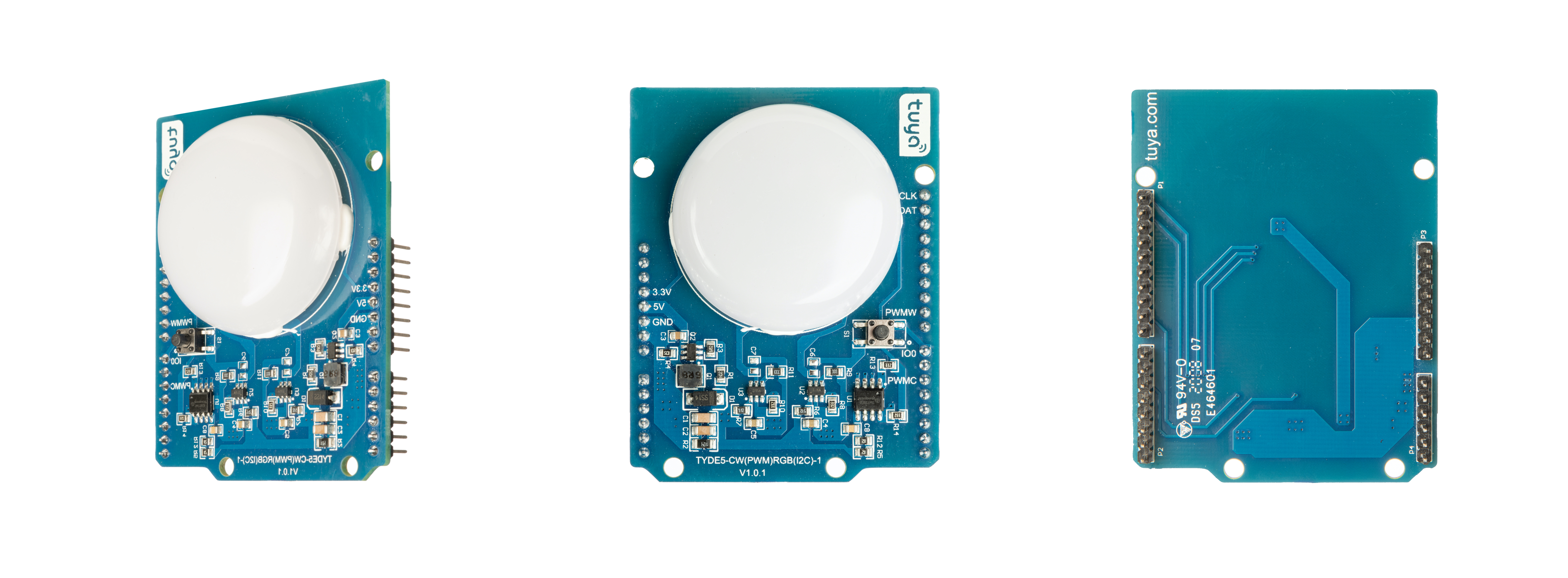
Tuya Sandwich (PWM + IIC) Lighting Board
The Tuya Arduino lighting development board (PWM+I2C) is a five-level pulse width modulation (PWM) dimmer LED controller, which applies to IoT products. The lighting development board (PWM + I2C) provides five dimming levels for the lighting function with warm white, cool white, RGB beads, and corresponding control chips.
Product features
The lighting function board is developed on the TYDE 5.0 platform, which allows you to quickly implement smart demos. The voltage inputted by Tuya Arduino lighting development board (PWM+I2C) hardware solution is boosted from 5V DC to 18V DC through DC-DC boost converter, which is used for the power supply of warm white, cool white, and RGB beads.
- DC-DC boost circuit adopts SY7208L step-up control chip.
- The control of cool white and warm white light adopts the SLM211A DC-DC step-down PWM linear constant current dimmer control chip.
- The control of RGB adopts the SM726EB DC-DC step-down I2C control linear constant current dimmer chip.
- Abundant peripheral PWM ports. It controls color temperature, brightness, and dazzling RGB through the following signals: PWMC, PWMW, DAT, and CLK.
- Provide abundant control ports. You can connect wireless modules such as Wi-Fi, Bluetooth, and Zigbee to control brightness, color temperature, and dazzling RGB by the corresponding PWM and I2C signals.
- Easy to verify the functionality of the configured firmware and view the test results. You can view the peripheral ports through the silk screen on the board, and directly connect the control port to use it.
Introduction to key components
The Tuya Arduino (PWM+I2C) lighting function board contains a DC-DC step-up chip, a CW two-level dimmer control chip, and an RGB control chip.
| Components | Description |
|---|---|
| Q2 (SY7208L) | High efficiency, 1 Mhz, 2A output step-up constant voltage controller, 3–25V input, and SOT23-6 package. |
| U1 (SM726EB) | Two-line three-level dimmer LED driver chip, which uses protocols of the clock signal and data signal, and ESOP8 package. |
| U2, U3 (SLM211A) | The linear constant current driver chip supports PWM dimmer and 15 mA–350 mA output current. It uses the SOT23-6 package. |
| D2–D6 (3535) | Three-in-one RGB beads with 3535 package, which supports the current of up to 20 mA. |
| D7–D15 C, W beads (2835) | D7–D15 C, W beads (2835). |
Introduction to I/O ports
The pins used in the PWM+I2C hardware solution are shown as below:
| I/O | Description |
|---|---|
| 5V | 5V power supply pin |
| GND | Power ground |
| 3.3V | 3.3V power supply pin |
| PWMC | Cool white PWM control signal, which is active high |
| PWMW | Warm white PWM control signal, which is active high |
| DAT | RGB I2C data control pin |
| CLK | RGB I2C clock control pin |
| I/O0 | The button network configuration pin, which is active low. |
Technical requirements
- Power supply voltage: 3.3V and 5V.
- The average current of 3.3V power supply: 80 mA. It has an average output current of 200 mA and the peak value is 450 mA.
- The maximum output current of 5V power supply: 200 mA.
Schematic diagram and PCB
-
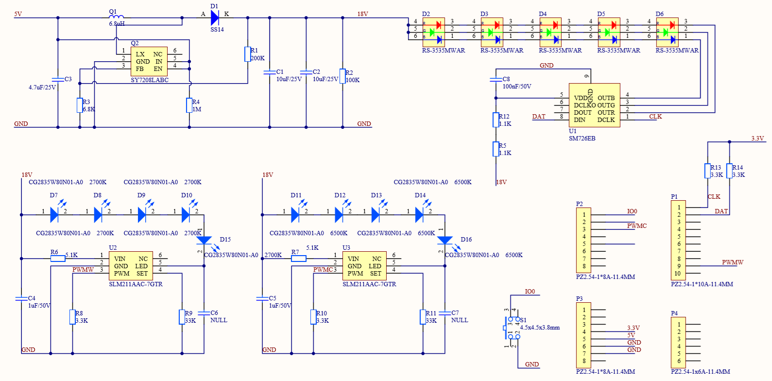
Schematic diagram of Tuya Sandwich (PWM+I2C) lighting function board:
-
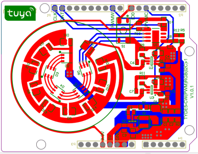
PCB of Tuya Sandwich (PWM+I2C) lighting function board:
Things to note
- The development board needs to be used with the control board and the power supply board.
- The power supply of the development board is 5V. It has a 3.3V port. 3.3V and 5V power supplies share the GND port.
- The development board supports PWM+I2C, and the RGB control does not support PWM.
- Do not insert the I/O pin into the power port to prevent a chip breakdown.
- The PWM and I2C signal controls of ports on the development board correspond to each other.
Reference
Is this page helpful?
YesFeedbackIs this page helpful?
YesFeedback


