MCU Integration Protocol
Serial communication convention
- Baud: 115200
- Data bit: 8
- Parity check: none
- Stop bit: 1
- Data flow control: none
- MCU: microcontroller unit. Your MCU communicates with Tuya’s Wi-Fi modules through the serial protocol. This protocol is designed to enable full-duplex communication between the device and the server.
Frame format description
| Field | Length (byte) | Description |
|---|---|---|
| Header | 2 | It is fixed to 0x55aa. |
| Version | 1 | It is used for updates and extensions. |
| Command | 1 | Frame type |
| Data length | 2 | Big-endian |
| Data | N | None |
| Checksum | 1 | Start from the header, add up all the bytes, and then divide the sum by 256 to get the remainder. |
-
All data greater than 1 byte is transmitted in big-endian format.
-
All sample data in the protocol are in hexadecimal format.
-
The Wi-Fi module sends packets and waits for response packets. If no response is received within one second, the unanswered packets will be retransmitted three times.
-
Generally, one command is sent by one party and received by the other party synchronously. That is, one party sends a command and waits for a response from the other party. If the sender does not receive a correct response packet within a specified time period, the transmission times out, as shown in the following figure.
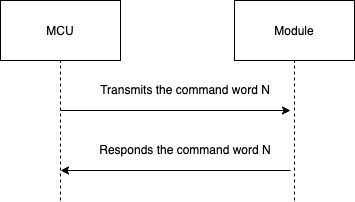
Note: For specific communication modes, see the protocol list in this topic.
-
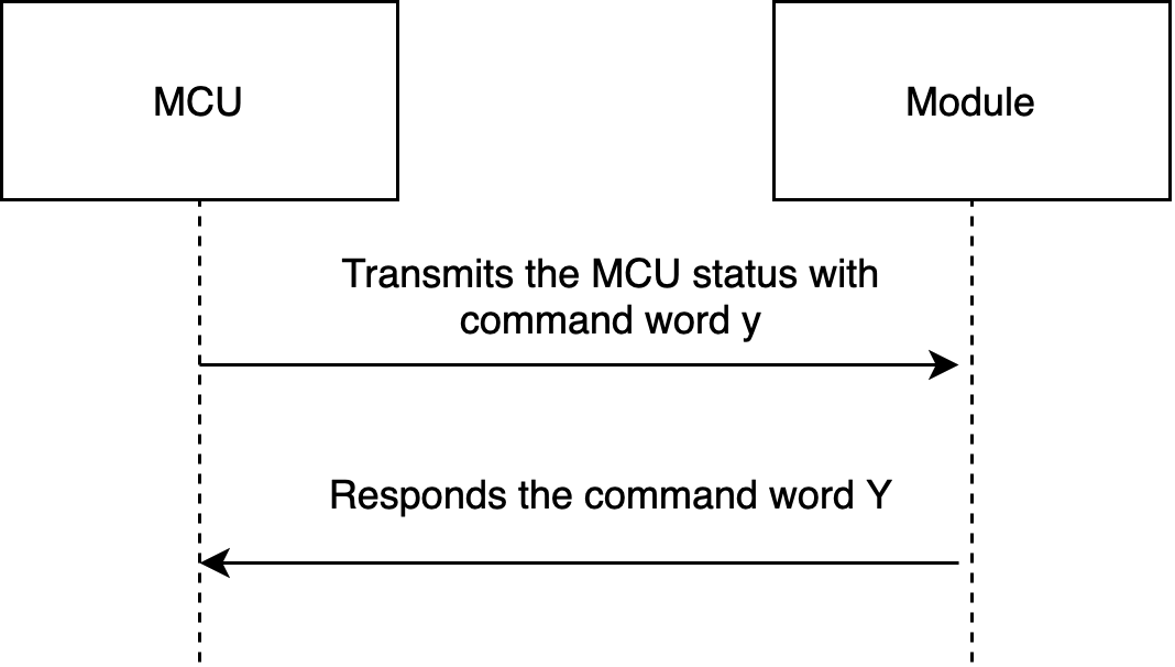
The MCU reports status synchronously. Assume that the MCU reports a command
y. The data transmission is as follows.The MCU reports statistical data:
Protocol description
Query product information (CMD: 0x01)
Product information consists of the product ID and MCU software version number.
- Product ID (PID): It is automatically generated for each product created on the Tuya Developer Platform to record product information in the cloud.
- MCU software version format: It is expressed in dot-decimal notation,
x.x.x(0 ≤ x ≤ 99), andxis a decimal digit.
The module sends the following command:
| Field | Length (byte) | Description |
|---|---|---|
| Header | 2 | 0x55aa |
| Version | 1 | 0x00 |
| Command | 1 | 0x01 |
| Data length | 2 | 0x0000 |
| Data | 0 | None |
| Checksum | 1 | Start from the header, add up all the bytes, and then divide the sum by 256 to get the remainder. |
The module sends the following command:
55 aa 00 01 00 00 00
The MCU returns the following command:
| Field | Length (byte) | Description |
|---|---|---|
| Header | 2 | 0x55aa |
| Version | 1 | 0x00 |
| Command | 1 | 0x01 |
| Data length | 2 | N |
| Data | N | {"p”:”vHXEcqntLpkAlOsy”, "v”:”1.0.0”,”n”:0,”cap”:0} |
| Checksum | 1 | Start from the header, add up all the bytes, and then divide the sum by 256 to get the remainder. |
For example, {"p”:”vHXEcqntLpkAlOsy”,"v”:”1.0.0”,”n”:0,”cap”:0}
-
pindicates the product ID isvHXEcqntLpkAlOsy, mapping the PID of a product created on the Tuya Developer Platform. -
vindicates the MCU version is 1.0.0. -
The
nfield (optional) indicates the network pairing mode. If you leave this field blank, users can switch between EZ mode (Wi-Fi Easy Connect ) and access point (AP) mode. Wi-Fi locks do not support pairing mode switching currently.0: EZ mode and AP mode coexist. The module supports EZ mode and AP mode, without requiring any manual switching operation.1: Only AP mode is supported. Users can pair devices only through AP mode.
-
The
capfield indicates device capabilities:bit0: indicates whether the device supports the photo upload function.0: not support.1: support.bit1: indicates which communication method the device uses to upload photos.0: serial port.1: serial peripheral interface (SPI).bit2: indicates whether the device supports connection to mobile network operators.0: not support.1: support. This functionality is not supported currently.bit3: indicates whether the device supports notification of module resetting.0: not support.1: support.- The other bits are not used and 0 is set in their bit positions. Reserved bits should be set to 0.
The MCU returns the following command:
55 aa 00 01 00 24 7b 22 70 22 3a 22 76 48 58 45 63 71 6e 74 4c 70 6b 41 6c 4f 73 79 22 2c 22 76 22 3a 22 31 2e 30 2e 30 22 7d bf
Report network status (CMD: 0x02)
| Network status | Description | Status value |
|---|---|---|
| Status 1 | EZ mode status. | 0x00 |
| Status 2 | AP mode status. | 0x01 |
| Status 3 | The Wi-Fi network is set up but cannot connect to the router. | 0x02 |
| Status 4 | The Wi-Fi network is set up and connects to the router. | 0x03 |
| Status 5 | The network connects to the router and the cloud. | 0x04 |
| Status 6 | The Wi-Fi device is in low power mode. | 0x05 |
-
Device network status: 1. EZ mode status. 2. AP mode status. 3. The Wi-Fi network is set up but cannot connect to the router. 4. The Wi-Fi network is set up and connects to the router. 5. The network connects to the router and the cloud.
-
When Wi-Fi network status changes, the module sends the current status to the MCU.
-
The MCU can get the current network status to update the app on current status 1 and status 2.
-
Router compatibility issues might occur when pairing is performed through EZ mode. In this case, AP mode can be used to pair the device.
-
Before pairing, the powered-on module runs in low power mode by default. After the MCU sends a command to reset Wi-Fi, the module is ready to be paired.
-
When a device is removed from the app, the module enters the low power mode. After the MCU sends a command to reset Wi-Fi, the module is ready to be paired.
-
If the module fails to connect to the router within 10 seconds and is powered off, it will run in the previous pairing status after powered on next time.
The module sends the following command:
| Field | Length (byte) | Description |
|---|---|---|
| Header | 2 | 0x55aa |
| Version | 1 | 0x00 |
| Command | 1 | 0x02 |
| Data length | 2 | 0x0001 |
| Data | 1 | Indicates Wi-Fi module status: 0x00: status 1 0x01: status 2 0x02: status 3 0x03: status 4 0x04: status 5 0x05: status 6 0x06: status 7 |
| Checksum | 1 | Start from the header, add up all the bytes, and then divide the sum by 256 to get the remainder. |
The module sends the following command:
55 aa 00 02 00 01 04 06 (The network connects to the router and the cloud.)
The MCU returns the following command:
| Field | Length (byte) | Description |
|---|---|---|
| Header | 2 | 0x55aa |
| Version | 1 | 0x00 |
| Command | 1 | 0x02 |
| Data length | 2 | 0x0000 |
| Data | 0 | None |
| Checksum | 1 | Start from the header, add up all the bytes, and then divide the sum by 256 to get the remainder. |
The MCU returns the following command:
55 aa 00 02 00 00 01
Reset Wi-Fi (CMD: 0x03)
-
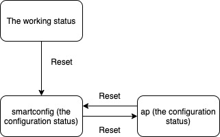
If EZ mode and AP mode coexist, the module still works in this coexistence mode after reset.
-
If only AP mode is used, the module still works in this AP-only mode after reset.
-
If AP mode and EZ mode are switched alternately, the pairing mode is changed after reset, as shown below:
The MCU sends the following command:
| Field | Length (byte) | Description |
|---|---|---|
| Header | 2 | 0x55aa |
| Version | 1 | 0x00 |
| Command | 1 | 0x03 |
| Data length | 2 | 0x0000 |
| Data | 0 | None |
| Checksum | 1 | Start from the header, add up all the bytes, and then divide the sum by 256 to get the remainder. |
The MCU sends the following command:
55 aa 00 03 00 00 02
The module returns the following command:
| Field | Length (byte) | Description |
|---|---|---|
| Header | 2 | 0x55aa |
| Version | 1 | 0x00 |
| Command | 1 | 0x03 |
| Data length | 2 | 0x0000 |
| Data | 0 | None |
| Checksum | 1 | Start from the header, add up all the bytes, and then divide the sum by 256 to get the remainder. |
The module returns the following command:
55 aa 00 03 00 00 02
Report real-time status (CMD: 0x05)
Scenario: This command allows devices that require real-time pushes, such as alarms, to make quick status reporting.
The MCU can report real-time status data through this protocol.
-
Status data is directly reported to the cloud, so the device must be connected to the cloud already. Otherwise, data reporting failed.
-
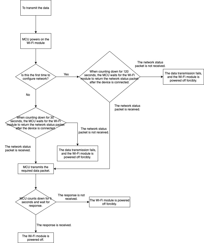
Using this synchronous command, the MCU reports data and waits five seconds for a response from the module.
-
The module sends the MCU a network status packet indicating connectivity to the server and then the MCU sends the status packet. Cloud storage is not provided for such data upload. If the MCU does not receive a network status packet within eight seconds, it will force the module to power off.
-
You can set packets to be transmitted in single or multiple data units. For more information about packets, see the examples in this section.
Operation process:
The MCU sends the following command:
| Field | Length (byte) | Description |
|---|---|---|
| Header | 2 | 0x55aa |
| Version | 1 | 0x00 |
| Command | 1 | 0x05 |
| Data length | 2 | It depends on types and the number of data units of status. |
| Data | N | Single or multiple data units of status. |
| Checksum | 1 | Start from the header, add up all the bytes, and then divide the sum by 256 to get the remainder. |
The module returns the following command:
| Field | Length (byte) | Description |
|---|---|---|
| Header | 2 | 0x55aa |
| Version | 1 | 0x00 |
| Command | 1 | 0x05 |
| Data length | 2 | 0x0001 |
| Data | 1 | 0x00: success. 0x01: failure. |
| Checksum | 1 | Start from the header, add up all the bytes, and then divide the sum by 256 to get the remainder. |
Report a single data unit of status
The DP 109 is a Boolean variable, and the value is 1.
55 aa 00 05 00 05 6d 01 00 01 01 79
Report multiple data units of status
The DP 109 is a Boolean variable, and the value is 1.
The DP 102 is a string variable, and the value is 201804121507. The value is transferred in ASCII mode.
55 aa 00 05 00 15 6d 01 00 01 01 66 03 00 0c 32 30 31 38 30 34 31 32 31 35 30 37 5d
Module sends command (CMD:0x09)
The module sends commands to the MCU in an asynchronous way. The MCU acknowledges receipt of the command and executes a specific operation. Then, it sends data of status-changed DPs to the module.
The module sends the following command:
| Field | Length (byte) | Description |
|---|---|---|
| Header | 2 | 0x55aa |
| Version | 1 | 0x00 |
| Command | 1 | 0x09 |
| Data length | 2 | Depends on the type and number of command data units. |
| Data | N | Command data units |
| Checksum | 1 | Start from the header, add up all the bytes, and then divide the sum by 256 to get the remainder. |
The module sends a command. The DP 3 of the device switch is a Boolean variable. The value is 1, which indicates switching on the device.
55 aa 00 09 0005 03 01 00 01 01 13
The MCU returns the following command:
| Field | Length (byte) | Description |
|---|---|---|
| Header | 2 | 0x55aa |
| Version | 1 | 0x00 |
| Command | 1 | 0x09 |
| Data length | 2 | 0x0000 |
| Data | 0 | None |
| Checksum | 1 | Start from the header, add up all the bytes, and then divide the sum by 256 to get the remainder. |
The MCU acknowledges receipt of the message:
55 aa 03 09 00 00 0b
Get local time (CMD: 0x06)
-
When the MCU receives the packet indicating the module is connected to the cloud, it sends a packet to get the local time.
-
The request might fail due to poor network connectivity. For time-dependent devices such as door locks, if the local time is not accurate, the request will fail. Set an interval of three seconds to ensure the time data can be obtained successfully.
-
Every time the module is powered on, it cannot get the time data until it is connected to the server and then synchronizes time with the server.
The MCU sends the following command:
| Field | Length (byte) | Description |
|---|---|---|
| Header | 2 | 0x55aa |
| Version | 1 | 0x00 |
| Command | 1 | 0x06 |
| Data length | 2 | 0x0000 |
| Data | 0 | None |
| Checksum | 1 | Start from the header, add up all the bytes, and then divide the sum by 256 to get the remainder. |
The MCU gets the local time:
55 aa 00 06 00 00 05
The module returns the following command:
| Field | Length (byte) | Description |
|---|---|---|
| Header | 2 | 0x55aa |
| Version | 1 | 0x00 |
| Command | 1 | 0x06 |
| Data length | 2 | 0x0008 |
| Data | Data | The data length is 8 bytes: Data[0]: indicates whether the local time is obtained successfully. 0: failure. 1: success. Data[1]: indicates the year. For example, 0X00 indicates the year 2000. Data[2]: indicates the month, ranging from 1 to 12. Data[3]: indicates the day, ranging from 1 to 31. Data[4]: indicates the hour, ranging from 0 to 23. Data[5]: indicates the minute, ranging from 0 to 59. Data[6]: indicates the second, ranging from 0 to 59. Data[7]: indicates the week, ranging from 1 to 7. 1 indicates Monday. |
| Checksum | 1 | Start from the header, add up all the bytes, and then divide the sum by 256 to get the remainder. |
The module returns the local time:
55 aa 00 06 00 08 01 12 09 11 10 09 05 01 59
The preceding example indicates the local time of Monday, September 17, 2018, 16:09:05.
-
For example, if the device is activated in mainland China, the local time is Beijing time (GMT+08:00).
-
If the device is activated in other countries or regions, the local time is the time zone in which the device is located.
Get the GMT (CMD: 0x07)
-
GMT is independent of the time zone and DST. If the device has a dynamic password function, such as a door lock, but does not need to display the local time, the device only needs to implement GMT and report data with GMT through the record-type reporting channel.
-
If a device with a dynamic password function, such as a door lock, needs to display the local time, while the GMT is used, the device must store the time zone offset. The displayed local time is calculated by adding the time zone offset to the GMT. Report data with GMT through the record-type reporting channel.
-
Every time the module is powered on, it cannot get the time data until it is connected to the server and then synchronizes time with the server.
The MCU sends the following command:
| Field | Length (byte) | Description |
|---|---|---|
| Header | 2 | 0x55aa |
| Version | 1 | 0x00 |
| Command | 1 | 0x10 |
| Data length | 2 | 0x0000 |
| Data | 0 | None |
| Checksum | 1 | Start from the header, add up all the bytes, and then divide the sum by 256 to get the remainder. |
The MCU gets the GMT:
55 aa 00 10 00 00 0F
The module returns the following command:
| Field | Length (byte) | Description |
|---|---|---|
| Header | 2 | 0x55aa |
| Version | 1 | 0x00 |
| Command | 1 | 0x10 |
| Data length | 2 | 0x0008 |
| Data | 8 | The data length is 8 bytes: Data[0]: indicates whether the local time is obtained successfully. 0: failure. 1: success. Data[1]: indicates the year. For example, 0X00 indicates the year 2000. Data[2]: indicates the month, ranging from 1 to 12. Data[3]: indicates the day, ranging from 1 to 31. Data[4]: indicates the hour, ranging from 0 to 23. Data[5]: indicates the minute, ranging from 0 to 59. Data[6]: indicates the second, ranging from 0 to 59. Data[7]: indicates the week, ranging from 1 to 7. 1 indicates Monday. |
| Checksum | 1 | Start from the header, add up all the bytes, and then divide the sum by 256 to get the remainder. |
The module returns the GMT:
55 aa 00 10 00 08 01 12 09 11 08 15 03 01 65
The preceding example indicates the GMT of Monday, September 17, 2018, 08:21:03.
Wi-Fi functional test (CMD: 0x07)
-
Scan the specified SSID tuya_mdev_test, and return the result and signal strength in the percentage.
-
The MCU triggers a production test after the Wi-Fi module is powered on and initialized. That is, the test should be initiated after the MCU gets product information. Otherwise, the test fails or returns no result.
-
This command is mostly used for testing the finished product during mass production.
-
The router must support the 2.4 GHz band. Its password is user-defined.
The MCU sends the following command:
| Field | Length (byte) | Description |
|---|---|---|
| Header | 2 | 0x55aa |
| Version | 1 | 0x00 |
| Command | 1 | 0x07 |
| Data length | 2 | 0x0000 |
| Data | Data | None |
| Checksum | 1 | Start from the header, add up all the bytes, and then divide the sum by 256 to get the remainder. |
The MCU triggers a Wi-Fi functional test:
55 aa 00 07 00 00 06
The module returns the following command:
| Field | Length (byte) | Description |
|---|---|---|
| Header | 2 | 0x55aa |
| Version | 1 | 0x00 |
| Command | 1 | 0x07 |
| Data length | 2 | 0x0002 |
| Data | 2 | The data length is 2 bytes. If Data[0] is 0x00, the test failed. If Data[0] is 0x01, the test succeeded. If Data[0] is 0x01, Data[1] indicates the signal strength, ranging from 0 to 100, 0 for the weakest and 100 for the strongest. If Data[0] is 0x00, Data[1] indicates failure reasons. 0x00 indicates the specified SSID is not found. 0x01, indicates the authorization key is not flashed to the module. |
| Checksum | 1 | Start from the header, add up all the bytes, and then divide the sum by 256 to get the remainder. |
The module returns the test result:
55 aa 00 07 00 02 01 50 59
The preceding example indicates that the Wi-Fi functional test is successful and the signal strength is 80.
Request Wi-Fi module firmware update (CMD: 0x0A)
- The MCU controls the on/off switch of the Wi-Fi module. It pulls firmware updates through the following command to have the module updated. The MCU determines whether to power off the Wi-Fi module according to the return packet from the Wi-Fi module. When the MCU sends the
0x0acommand but receives no response within five seconds, it powers off the Wi-Fi module. If the Wi-Fi module returns a packet indicating firmware update is in progress, the MCU will give it a 60-second timeout period. If the MCU does not receive a packet indicating a successful update after the timeout period, it will force the Wi-Fi module to power off.
The MCU sends the following command:
| Field | Length (byte) | Description |
|---|---|---|
| Header | 2 | 0x55aa |
| Version | 1 | 0x00 |
| Command | 1 | 0x0a |
| Data length | 2 | 0x0000 |
| Data | 0 | None |
| Checksum | 1 | Start from the header, add up all the bytes, and then divide the sum by 256 to get the remainder. |
The MCU requests Wi-Fi module firmware update:
55 aa 00 0a 00 00 09
The module returns the following command:
| Field | Length (byte) | Description |
|---|---|---|
| Header | 2 | 0x55aa |
| Version | 1 | 0x00 |
| Command | 1 | 0x0a |
| Data length | 2 | 0x0001 |
| Data | 1 | 0x00: Check for updates. The Wi-Fi module cannot be powered off. 0x01: Firmware is up to date. The Wi-Fi module is powered off. 0x02: Update is in progress. The Wi-Fi module cannot be powered off. 0x03: Update succeeded. The Wi-Fi module is powered off. 0x04: Update failed. The Wi-Fi module is powered off. |
| Checksum | 1 | Start from the header, add up all the bytes, and then divide the sum by 256 to get the remainder. |
The module returns the following update status:
55 aa 00 0a 00 01 00 0a indicates the update package is returned.
55 aa 00 0a 00 01 01 0b indicates the firmware is up to date.
Request MCU firmware update (CMD: 0x0C)
-
After the Wi-Fi module sends a command to the MCU indicating the firmware update is completed, all the MCU updates have been pulled from the server and transmitted through the serial port.
After the MCU receives the complete updates, the module sends a query to confirm update information. The MCU returns product information and the latest version number that should be consistent with the one recorded in the server. -
Currently, the maximum size of the MCU OTA updates is 480 KB.
-
You need to set the update method as silent update on the Tuya Developer Platform.
The MCU sends the following command:
| Field | Length (byte) | Description |
|---|---|---|
| Header | 2 | 0x55aa |
| Version | 1 | 0x00 |
| Command | 1 | 0x0c |
| Data length | 2 | 0x0000 |
| Data | 0 | None |
| Checksum | 1 | Start from the header, add up all the bytes, and then divide the sum by 256 to get the remainder. |
The MCU requests MCU firmware update:
55 aa 00 0c 00 00 0b
The module returns the following command:
| Field | Length (byte) | Description |
|---|---|---|
| Header | 2 | 0x55aa |
| Version | 1 | 0x00 |
| Command | 1 | 0x0c |
| Data length | 2 | 0x0001 |
| Data | 1 | 0x00: Check for updates. The Wi-Fi module cannot be powered off. 0x01: Firmware is up to date. The Wi-Fi module is powered off. 0x02: Update is in progress. The Wi-Fi module cannot be powered off. 0x03: Update succeeded. The Wi-Fi module is powered off. 0x04: Update failed. The Wi-Fi module is powered off. |
| Checksum | 1 | Start from the header, add up all the bytes, and then divide the sum by 256 to get the remainder. |
The module returns the following update status:
55 aa 00 0c 00 01 00 0c indicates the update package is returned.
55 aa 00 0c 00 01 01 0d indicates the firmware is up to date.
Start update (CMD: 0x0D)
- When the MCU triggers the Wi-Fi module to update the MCU firmware, the server has the latest MCU firmware, and the update method applies to the MCU, the module will return the size of the MCU update package.
The module sends the following command:
| Field | Length (byte) | Description |
|---|---|---|
| Header | 2 | 0x55aa |
| Version | 1 | 0x00 |
| Command | 1 | 0x0d |
| Data length | 2 | 0x0004 |
| Data | 4 | The bytes of the update package. The data type is an unsigned integer, and the data is stored in big-endian format. |
| Checksum | 1 | Start from the header, add up all the bytes, and then divide the sum by 256 to get the remainder. |
The module sends the file packet size:
55 aa 00 0d 00 04 00 00 68 00 78: the size of update package is 26624 bytes, namely 26 KB.
The MCU returns the following command:
| Field | Length (byte) | Description |
|---|---|---|
| Header | 2 | 0x55aa |
| Version | 1 | 0x00 |
| Command | 1 | 0x0d |
| Data length | 2 | 0x0000 |
| Data | 0 | None |
| Checksum | 1 | Start from the header, add up all the bytes, and then divide the sum by 256 to get the remainder. |
The MCU sends ACK message:
55 aa 00 0d 00 00 0c
Transmit update package (CMD: 0x0E)
-
The data format of updates transmission: packet offset (unsigned short) plus packet data.
-
If the MCU receives the frame with a data length equal to 4 bytes and the update packet offset is equal to or greater than the size of firmware, the packet transmission ends.
The module sends the following command:
| Field | Length (byte) | Description |
|---|---|---|
| Header | 2 | 0x55aa |
| Version | 1 | 0x00 |
| Command | 1 | 0x0e |
| Data length | 2 | The data length is the sum of 0x0004 and the packet length. |
| Data | N | The first four bytes are fixed as packet offset, and the latter bytes are the packet content. |
| Checksum | 1 | Start from the header, add up all the bytes, and then divide the sum by 256 to get the remainder. |
The module sends file data:
If the updates have 530 bytes, the MCU can skip the response to the last packet.
- For the first packet, packet offset is 0x00000000, and packet length is 256 bytes.
55aa 00 0e 0104 00000000 xx…xx XX
- For the second packet, packet offset is 0x00000100, and packet length is 256 bytes.
55aa 00 0e 0104 00000100 xx…xx XX
- For the third packet, packet offset is 0x00000200, and packet length is 18 bytes.
55aa 00 0e 0016 00000200 xx…xx XX
- For the last packet, packet offset is 0x00000212, and packet length is 0 bytes.
55aa 00 0e 0004 00000212 xx...xx XX
The MCU returns the following command:
| Field | Length (byte) | Description |
|---|---|---|
| Header | 2 | 0x55aa |
| Version | 1 | 0x00 |
| Command | 1 | 0x0e |
| Data length | 2 | 0x0000 |
| Data | 0 | None |
| Checksum | 1 | Start from the header, add up all the bytes, and then divide the sum by 256 to get the remainder. |
The MCU confirms each packet:
55aa 00 0e 0000 0d
Query signal strength of the connected router (CMD: 0x0B)
- To successfully send this command, the MCU must receive the network status packet that indicates the device is connected to the router successfully. Otherwise, the failure result will be returned.
The MCU sends the following command:
| Field | Length (byte) | Description |
|---|---|---|
| Header | 2 | 0x55aa |
| Version | 1 | 0x00 |
| Command | 1 | 0x0b |
| Data length | 2 | 0x0000 |
| Data | 0 | None |
| Checksum | 1 | Start from the header, add up all the bytes, and then divide the sum by 256 to get the remainder. |
The MCU gets the signal strength of the connected router:
55 aa 00 0b 00 00 0a
The module returns the following command:
| Field | Length (byte) | Description |
|---|---|---|
| Header | 2 | 0x55aa |
| Version | 1 | 0x00 |
| Command | 1 | 0x0b |
| Data length | 2 | 0x0002 |
| Data | 2 | The data length is 2 bytes. If Data[0] is 0x00, the test failed. If Data[0] is 0x01, the test succeeded. If Data[0] is 0x01, Data[1] indicates the signal strength, ranging from 0 to 100, 0 for the weakest and 100 for the strongest. If Data[0] is 0x00, Data[1] is 0x00, indicating the device fails to connect to the router. |
| Checksum | 1 | Start from the header, add up all the bytes, and then divide the sum by 256 to get the remainder. |
The module returns the current signal strength of 80:
55 aa 00 0b 00 02 01 50 5D
Data unit of status
- Data point command and status data unit are defined as follows:
| Data segment | Length (byte) | Description | |||
|---|---|---|---|---|---|
| dpid | 1 | The serial number of a data point | |||
| type | 1 | The specific data type of a data point is defined on the Tuya Developer Platform, which is represented by Value. | |||
| Type | Value | Length (byte) | Description | ||
| raw | 0x00 | N | Represents data point of the raw data type. The data is passed through the module to the cloud. | ||
| bool | 0x01 | 1 | Represents data point of Boolean data type. Values include 0x00 and 0x01. |
||
| value | 0x02 | 4 | Represents data point of the integer type. The data is represented in big-endian format. | ||
| string | 0x03 | N | Represents data point of string type. | ||
| enum | 0x04 | 1 | Represents data point of enum type, ranging from 0 to 255. | ||
| bitmap | 0x05 | 1/2/4 | Represents data point of fault type. Data greater than 1 byte is represented in big-endian format. | ||
| len | 2 | The length corresponds to the number of bytes of the value. | |||
| value | 1/2/4/N | Represented in hexadecimal format. Data greater than 1 byte is transmitted in big-endian format. |
-
Except for the
rawdata type, all others belong to the object type. -
The status data can contain command data units of multiple data points.
Things to note:
-
The whole protocol applies to devices that use Wi-Fi modules and cannot use an external power supply. During the development of MCU programs, power-off management is especially important. Under the precondition of completing the functions, try to reduce the power-on time of the Wi-Fi module to reduce the power consumption of devices. You can choose the required functions for data uploading depending on device features. During development, you can adjust relevant control logic as needed.
-
In many cases, a device works properly when the Wi-Fi function is not enabled. Due to various reasons, users might not use the Wi-Fi function. To reduce unnecessary power consumption when the Wi-Fi module is powered on in this case, you can design a physical button or an option on the device. When users press this button or enable this option, the MCU powers on the Wi-Fi module for data transmission only when data changes.
Notify status of module reset (CMD: 0x25)
| Status of module reset | Description | Status value |
|---|---|---|
| Status 1 | A local reset of the module is performed. | 0x00 |
| Status 2 | A remote reset of the module is performed on the app. | 0x01 |
| Status 3 | A factory reset is performed on the app. | 0x02 |
- Note: If the Wi-Fi module receives no response within one second after a packet is sent, the unanswered packets will be retransmitted three times at a one-second interval.
The module sends the following command:
| Field | Length (byte) | Description |
|---|---|---|
| Header | 2 | 0x55aa |
| Version | 1 | 0x00 |
| Command | 1 | 0x25 |
| Data length | 2 | 0x0001 |
| Data | 1 | The status of module reset: 0x00: A local reset of the module is performed. 0x01: A remote reset of the module is performed on the app. 0x02: A factory reset is performed on the app. 0x03: Clear the local data. The device is still paired. |
| Checksum | 1 | Start from the header, add up all the bytes, and then divide the sum by 256 to get the remainder. |
The MCU returns the following command:
| Field | Length (byte) | Description |
|---|---|---|
| Header | 2 | 0x55aa |
| Version | 1 | 0x00 |
| Command | 1 | 0x25 |
| Data length | 2 | 0 |
| Data | Data | None |
| Checksum | 1 | Start from the header, add up all the bytes, and then divide the sum by 256 to get the remainder. |
Get Wi-Fi status (CMD: 0x1A)
The MCU can get the Wi-Fi status through this command. For specific Wi-Fi status, see Report network status.
The MCU sends the following command:
| Field | Length (byte) | Description |
|---|---|---|
| Header | 2 | 0x55aa |
| Version | 1 | 0x00 |
| Command | 1 | 0x1A |
| Data length | 2 | 0x0000 |
| Data | Data | None |
| Checksum | 1 | Start from the header, add up all the bytes, and then divide the sum by 256 to get the remainder. |
The module returns the following command:
| Field | Length (byte) | Description |
|---|---|---|
| Header | 2 | 0x55aa |
| Version | 1 | 0x00 |
| Command | 1 | 0x1A |
| Data length | 2 | 0x0002 |
| Data | 2 | Data[0] indicates Wi-Fi working status: 0x00: status 1 0x01: status 2 0x02: status 3 0x03: status 4 0x04: status 5 0x05: status 6 0xff: invalid status. Initialization is not completed. Data[1] indicates whether the device is activated: 0x00: not activated. 0x01: activated. |
| Checksum | 1 | Start from the header, add up all the bytes, and then divide the sum by 256 to get the remainder. |
Get Unix timestamp (with time zone) (CMD: 0x1B)
The MCU can get a Unix timestamp, time zone, and daylight saving time (DST).
The MCU sends the following command:
| Field | Length (byte) | Description |
|---|---|---|
| Header | 2 | 0x55aa |
| Version | 1 | 0x00 |
| Command | 1 | 0x1B |
| Data length | 2 | 0x0000 |
| Data | Data | None |
| Checksum | 1 | Start from the header, add up all the bytes, and then divide the sum by 256 to get the remainder. |
The module returns the following command:
| Field | Length (byte) | Description |
|---|---|---|
| Header | 2 | 0x55aa |
| Version | 1 | 0x00 |
| Command | 1 | 0x1B |
| Data length | 2 | N |
| Data | 2 | Data[0] indicates whether the time is obtained successfully: 1: succeeded. 0: failed. Data[1] to Data[4]: Unix timestamp. Data[5] indicates whether time zone information is obtained successfully. 1: succeeded. 0: failed. Data[6]: 0: indicates local time ahead of GMT. 1: indicates local time behind GMT. Data[7] indicates the time zone. Data[8] indicates whether DST is in use in a time zone. 1: in use. 0: not in use. Data[9] to Data[12]: the timestamp when DST starts, in big-endian format. Data[13] to Data[16]: the timestamp when DST ends, in big-endian format. |
| Checksum | 1 | Start from the header, add up all the bytes, and then divide the sum by 256 to get the remainder. |
Appendix 1: Event code of photo uploading
| Event status | Description | Status value |
|---|---|---|
| Status 1 | Anti-pry alert | 0x0000 |
| Status 2 | Remote unlocking request | 0x0001 |
| Status 3 | Fingerprint attempt | 0x0002 |
| Status 4 | Password attempt | 0x0003 |
| Status 5 | Card attempt | 0x0004 |
| Status 6 | Face attempt | 0x0005 |
| Status 7 | Palm print attempt | 0x0006 |
| Status 8 | Finger vein attempt | 0x0007 |
| Status 9 | Unlock with fingerprint | 0x0008 |
| Status 10 | Unlock with password | 0x0009 |
| Status 11 | Unlock with card | 0x000A |
| Status 12 | Unlock with face recognition | 0x000B |
| Status 13 | Unlock with palm vein | 0x000C |
| Status 14 | Unlock with finger vein | 0x000D |
| Status 15 | Unlock with temporary password | 0x000E |
| Status 16 | Unlock with dynamic password | 0x000F |
| Status 17 | Remote unlocking | 0x0010 |
| Status 18 | Report offline password unlocking | 0x0011 |
Appendix 2: SPI configuration
Default parameters are as follows.
| Parameter name | Description | Status value |
|---|---|---|
| Clock | Clock rate | 6,000,000 |
| Clock mode | None | SPI_SCLK_Mode0 |
| Level of first byte | None | SPI_TCTRL_FBS_MSB |
| Cs | Chip select signal | Low level |
| Byte alignment | None | 8-bit |
Is this page helpful?
YesFeedbackIs this page helpful?
YesFeedback


